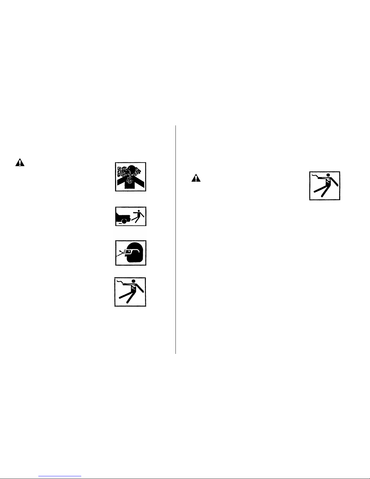
PDi DM-930 User manual

-1 0
DM-930
AUTOMOTIVE MULTIMETER
INSTRUCTION MANUAL
¦¸
Auto Power Off
42

12
Safety
DANGER
Engines produce carbon monoxide which is
odorless, can cause slower reaction time and
can lead to serious injury. When the engine is
operating, always keep service areas WELL
VENTILATED or attach the vehicle exhaust
system to the shop exhaust removal system.
Set the parking brake and block the wheels
before testing or repairing the vehicle. It is
especially important to block the wheels on
front-wheel drive vehicles; the parking brake
does not hold the drive wheels.
Wear an eye shield when testing or repairing
vehicles.
Exceeding the limits of this meter is dangerous.
This may expose you to serious or possibly fatal
injury. Carefully read and understand the
cautions and the specification limits of this
meter.
Voltage between any terminal and ground
must not exceed 600V DC or 600V AC.
Use caution when measuring voltage above
25VDC or 25VAC.
Circuit tested must be protected by a 20A fuse or circuit breaker.
Do not use the meter if it has been damaged.
Do not use any test leads if the insulation is damaged or if metal is
exposed.
Safety Cont’d
…
Danger
Avoid electrical shock: do not touch the test leads,
tips or the circuit being tested.
Do not try a voltage measurement with the test
leads in the 20Aor the mAterminal.
When testing for the presence of voltage or current, make sure the
meter is functioning correctly. Take a reading of a known voltage or
current before accepting a zero reading.
Choose the proper range and function for the measurement. Do not
try voltage or current measurements that may exceed the ratings
marked on the Function/Range switch or terminal.
When measuring current, connect the meter in series with the load.
Never connect more than one set of test leads to the meter.
Disconnect the live test lead before disconnecting the common test
lead.
The mA and the 20A terminals are protected by fuses. To avoid
possible injury or damage, use only on circuits limited to 400mA or
20A for 30 seconds.

34
Safety Cont’d
…
IMPORTANT
To maintain accuracy of the meter, replace the exhausted battery
immediately when the battery symbol “ “ appears on the meter
display.
Avoid measuring error from outside interference. Keep the meter
away from spark plugs or coil wires.
Avoid damaging the meter when testing voltage. Disconnect the test
leads from the test points before changing functions.
Do not exceed the limits shown in the table below:
Function
Terminal
Input limit
DC/AC Volts,
Ohm/Continuity
/Diode,CAP.
Adaptor, Type-
K
TEMP.,Hz,%Duty,
mS Dwell, RPM
V-Ω-RPM
600Volts AC/ DC
AC/DC
μ
A mA
μ
A / mA
400mA DC/AC
AC/DC20A
20A
*20ADC/AC
*20 Amp measurement for 30 seconds maximum.
Getting Started
This chapter will help you get started. It describes the basic functions of
the Meter.
Meter Basics
1.Digital LCD display
Display features:
1a. Symbols to identify function
1b. Four character digital display
The digital display is best for stable
input. The bar graph is best for rapidly
changing input.
2.Function buttons
Press the button to select a function. A
symbol will display to verify your
choice.
3.Rotary Function Dial
Turn this switch to select a function or
turn the meter OFF.
4.Volts Terminal
The Red test lead is used to measure Amps, Volts, Ohms, TEMP, Hz,
RPM, Cap, mS and Dwell.
The Black test lead is used in the Common (COM) terminal for all tests
and measurements.
¦¸
Auto Power Off
4 2
1a
1b
2
3
4

56
LCD DISPLAY SYMBOLS
-8.8.8.8 LCD display reading
Continuity
Low Battery
Diode
HData Hold
AUTO AutoRanging
AC Alternating Current or Voltage
DC Direct Current or Voltage
nnano (10-9) (capacitance)
µmicro (10-6) (amps, cap)
mmilli (10-3) (volts, amps) A Amps
kkilo (103) (ohms) F Farads (capacitance)
Mmega (106) (ohms) ΩOhms
Hz Hertz (frequency) V Volts
%Percent (duty ratio)
ºF Degrees Fahrenheit
ºC Degrees Centigrade
Function Buttons
Mode Button
Press the mode pushbutton to select
the following functions;
DC/AC Voltage, DC/AC Current
Resistance, Diode, Continuity &
Capacitance
Manual Range & Stroke 4/2(DIS),
Hz, %, ms +, CYL Button
Press to this button to select;
STROKE 4, 2DIS, Hz ,%, ms+ ,
CYL range & V/A/ Resistance manual
Range
Manual Ranging
The meter turns on in the autoranging mode.
Press the Range button to go to manual ranging.
The display icon " " will appear. Each press of the range button will
step to the next range as indicated by the units and decimal point
location. Press and hold the Range button for two seconds to return to
autoranging.
Data Hold
The Data Hold function allows the
meter to "freeze" a measurement for
later reference.
1. Press the HOLD button to “freeze”
the reading on the display.
The HOLD indicator, “H”, will appear
in the upper left corner of the display.
2. Press the HOLD button again to return
to normal operation.
Auto Power Off
4 2
Auto Power Off
4 2
Auto Power Off
4 2

78
Peak Hold
The Peak Hold function captures
the peak AC or DC voltage or current.
The meter can capture negative
or positive peaks as fast as
1 millisecond in duration.
1. Turn the function dial to the A or V position.
2. Press and hold the PEAK button until “CAL” appears in the
display. This procedure will zero the range selected & meter
go to manual ranging.
3. Press the PEAK button, Pmax will display.
4. The display will update each time a higher positive peak
occurs.
5. Press the PEAK button again, Pmin will display. The display
will now update and indicate the lowest negative peak.
6. To return to normal operation, press and hold the PEAK
button until the Pmin or Pmax indicator switches off.
Note: If the Function switch position is changed after a calibration
the Peak Hold calibration must be repeated for the new function
selected.
MAX/MIN
1. Press the MAX/MIN key to activate the MAX/MIN recording
mode. The display icon "MAX or MIN" will appear. The meter
will go to manual ranging & display and hold the maximum or
minimum reading and will update only when a new “MAX or
MIN” occurs.
2. Press the MAX/MIN key and a blinking “MAX MIN” will appear.
The meter will display the present reading, but will continue to
update and store the max and min readings.
To exit MAX/MIN mode press and hold the MAX/MIN key for 2 seconds.
Backlight Button
1. Press the BACKLIGHT button to turn the backlighting ON.
2. Press the BACKLIGHT button again to turn the backlighting OFF.
Auto Power Off
4 2
Auto Power Off
4 2
Auto Power Off
4 2

910
Meter Functions - Voltage (V)
Select the Volts “V” range with the
rotary switch.
The meter will automatically select
best voltage (V) range.
Select DCV or ACV with the function
dial.
Insert:
Black lead in COM terminal.
Red lead in V-
Ω
-RPM terminal
Touch the Black probe to ground or to
the negative (-) circuit
Touch the Red probe to the circuit
coming from the power source
IMPORTANT: Voltage must be
measuring in parallel (Red probe
measuring circuit from power
source).
Meter Functions – Resistance (
Ω
)
IMPORTANT: If you are testing an
application that has capacitors in the
circuit, be sure to turn the power OFF
on the test circuit and discharge all
capacitors. Accurate measurement is
not possible if external or residual
voltage is present.
Select the Resistance “
Ω
”
range with the function dial.
Select the Resistance “
Ω
”
function with the Mode button.
Please Note: the DM-930 defaults to
resistance.
Insert:
Black lead in COM terminal.
Red lead in V-
Ω
-RPM terminal.
Touch the test lead probes across the
resistor to be tested.
WARNING
When measuring voltage,
be sure the Red test lead is
in the terminal marked “V”.
If the test lead is in an Amp
(A) or Milliampere (mA)
terminal, you
may damage
your meter and could be
injured.
¦¸
Auto Power Off
4 2
Black- Red +
¦¸
Auto Power Off
4 2
Black- Red +

11 12
Meter Functions –Diode Check ( )
IMPORTANT: Turn the power OFF to
the test circuit
Select the Diode Check “ “
function with the function dial and
mode button.
Insert:
Black lead in COM terminal.
Red lead in V-
Ω
-RPM terminal.
Touch the Black test probe to the
negative (-) side of the diode.
Touch the Red test probe to the positive
(+) side of the diode. Reverse the
probes: Black to the positive (+) side and
Red to the negative (-) side.
Note:
A “good” diode will read low in one
direction and high in the other direction
when the probes are reversed (or vice
versa).
A defective diode will have the same
reading in both directions or read
between 1.0 and 3.0 V in both
directions.
Diode
- to +
Reverse Probes + to -
Good
.4 to .9V
OL
OL
.4 to .9V
Bad
OL
1.0 to 3.0V
1.0 to
OL
.4 to .9V
.4 to .9V
OL
OL
.000V .000V
Meter Functions – Capacitance ( CAP )
IMPORTANT: Turn the power OFF to the test
circuit before performing any work.
Select the Capacitance “ CAP “
function with the function dial and
MODE button.
Insert:
Black lead in COM terminal.
Red lead in V-
Ω
-RPM terminal
CAUTION: When checking in-circuit
capacitance, be sure
that the circuit has all power
removed and all capacitors are
fully discharged.
Touch the test lead probes across the
capacitance circuit to be tested.
Read the measured value from the
LCD display.
Note:
1. The bar graph is disabled in capacitance measurement mode.
However, since the measurement time of 4mF and 40mF modes is
quite long (3.75s and 7.5s respectively) the bar graph is used to
display the time remaining to complete the measurement.
2. In order to obtain an accurate reading, a capacitor must be
discharged before measurement begins. The meter has a built-in
discharge mode to automatically discharge the capacitor. In
discharge mode, the LCD displays “DIS.C”
3. Discharging through the chip is quite slow. It is recommended to
discharge the capacitor by other means when possible.
¦¸
Auto Power Off
4 2
Black- Red +
¦¸
Auto Power Off
42
Black- Red +

13 14
Meter Functions – Audible Continuity ( )
IMPORTANT: Turn the power OFF
on the test circuit
Select the Audible Continuity
““ function with the function
dial and mode button.
Insert:
Black lead in COM terminal.
Red lead in V-
Ω
-RPM terminal.
Touch one test probe to each end of
the circuit to be tested.
Circuit complete, the meter will
beep continuously.
Circuit open, there is no beep and
the display shows to OL (over limit).
Meter Functions – AC or DC Current (A)
IMPORTANT: All current measured
flows through the meter.
It is important that you:
Do Not Exceed 30 seconds when
measuring continuous current
between 1A-20A. Allow five
minutes for cool down before
continuing with any other
measurements.
Select the “20A” or “mA” range
with the function dial.
Press the mode button to select
AC or DC.
Insert:
Black lead in COM terminal.
Red lead in the 20A or mA terminal
(select 20A if you are unsure of the
current draw).
IMPORTANT: Turn OFF all power to
the circuit or disconnect the circuit
from the power source.
Connect:
The Red probe to the side of the
circuit closest to the power source.
The Black probe to the side of the
circuit to ground.
Turn the power ON and test.
Meter Functions –Temperature (°C / °F )
IMPORTANT: To avoid heat
damage to the meter, keep it
away from sources of very high
temperature. The life of the
Temperature Probe is also
reduced when subjected to
very high temperatures. Probe
operating range is
–58o to 482oF.
Select the Temperature
“°C or °F” function with the
function dial.
Insert the temperature probe
connector into the K-type
thermocouple adapter. Insert the
adapter into the front of the meter
as shown.
Touch the end of the temperature
sensor to the area or surface of
the object to be measured.
Note:
Current must always be
measured with the meter
test probes connected in
series, as described.
¦¸
Auto Power Off
4 2
Black- Red +
circuit open
no beep
¦¸
Auto Power Off
4 2
Black-
Red +
round
ide
¦¸
Auto Power Off
42
Temperature
Sensor
Temperature probe

15 16
Meter Functions – Frequency(Hz)
Select the “Hz” Frequency
function with the function dial.
Insert:
Black lead in COM terminal.
Red lead in V-
Ω
-RPM terminal.
Connect the Black test probe to
ground.
Connect the Red test probe to the
“signal out” wire of the sensor to be
tested.
Meter Functions-Dwell ( )
Select the “DWELL” function
with the rotary switch.
Insert:
Black lead in COM terminal.
Red lead in V-
Ω
-Hz-RPM
terminal.
Connect the Black test probe to
ground.
Connect the Red test probe to the
wire that connects to the breaker
points (see illustration).
Meter Functions - Duty Cycle (%)
Select the “% Duty” Cycle
function with the function dial.
Insert:
Black lead in COM terminal.
Red lead in V-
Ω
-%-RPM terminal.
Connect the Black test probe to
ground.
Connect the Red test probe to the
signal wire circuit.
The illustration for a mixture control
solenoid is shown with the metering
rod in the closed position. The meter
will display the percentage of time the
plunger is in the closed position. (low
duty cycle) during one duty cycle.
Meter Functions - ms-PULSE (Pulse Width) & ms-
PERIOD (Period)
Pulse Width is the length of time an actuator is energized. For example,
fuel injectors are activated by an electronic pulse from the Engine
Control Module (ECM).
This pulse generates a magnetic field that pulls the injectors nozzle
¦¸
Auto Power Off
42
Black- Red +
To breaker
points
¦¸
Auto Power Off
42
Black- Red +
"Signal Out"
Side Ground
Side
"Volta ge In"
Side
¦¸
Auto Power Off
42
Black- Red +
Mixture
Control
Shown
Mixture
Control
Shown

17 18
valve open.
When the pulse ends, the injector nozzle is closed.
This open to close time is the Pulse Width and is measured in
milliseconds (ms).
The most common automotive application for measuring pulse width is
on fuel injectors.
You can also measure the pulse width of the fuel mixture control
solenoid and the idle air control motor.
This exercise shows how to measure Pulse Width on Port Fuel
injectors.
(continued on next page)
To measure pulse width (mS):
Select the “mS-Pulse” function
with the function dial.
Press the ±TRIG button for 2
seconds until the negative (-)
trigger slope is displayed on the
upper left side of the display.
NOTE : The applied time for most
fuel injectors is displayed
on the negative (-) slope.
Insert:
Black lead in COM jack.
Red lead in V-
Ω
-RPM jack.
Connect:
Jumper wires between the fuel
injector and the harness connector.
Connect black test probe to a good
ground at the fuel injector or the
negative (-) vehicle battery post.
Connect red test probe to the fuel
injector solenoid driver input on the
jumper cable.
Start the engine. A pulse width in
milliseconds should be read.
Note: Initially, the unit will read “OL”,
then readings will descend and
stabilize to the actual pulse width. If
“OL” remains, re-check your
connections.
Meter Functions-RPM/
×
10RPM
Select the RPM range with the
function dial. OR
Select the
×
10RPM range with the
function dial (1,000 to 12,000 RPM).
Multiply the displayed reading by
ten to get actual RPM.
Press STROKE / DIS
button to select through
RPM for 4-stroke, RPM
for 2-stroke and DIS ignitions.
Connect the inductive pickup
by connecting leads to the
meter.
Black lead in COM terminal.
Red lead in V-
Ω
-RPM terminal.
Clamp the inductive pickup to a
spark plug wire. If no reading is
received, unhook the clamp, turn it
over and connect again.
4
2
4
2
¦¸
Auto Power Off
4 2
Black- Red +
Mixture
Control
Shown
GOOD
GROUND
JUMPER LEAS
FROM PORT
FULL INJECTOR
¦¸
Auto Power Off
4 2

19 20
Note:
Position the inductive pick-up as far away from the distributor and
the exhaust manifold as possible.
Position the inductive pick-up within six inches of the spark plug or
move it to another plug wire if no reading or an erratic reading is
received.
RPM 4 :For RPM of 4-stroke engines which have 1 ignition on every
4 engine strokes
RPM 2 : For RPM of DIS (Distributorless Ignition System) & 2-stroke
engines which have 1 ignition on every 2 engine strokes
PLEASE NOTE
:
THE RPM PICK-UP HAS AN ADJUSTABLE SENSITIVITY SWITCH THAT CAN
ALSO BE USED TO CORRECTAN UNSTABLE READING.
。
As you are measuring, keep the meter away from the engine to ensure
a stable reading.
General Specifications
The instrument complies with: IEC 1010-1 EN61010-1.
Insulation: Class2, Double insulation.
Overvoltage category: CATIII1000V/CATIV600V.
Display: 4000 counts LCD display with function indication.
Polarity: Automatic, (-) negative polarity indication.
Overrange: “OL” mark indication.
Low battery indication: The “ ” is displayed when the battery
voltage drops below the operating level.
Measurement rate: 2 times per second, nominal.
Auto power off: Meter automatically shuts down after approx. 30
minutes of inactivity.
Operating environment: 0ºC to 50⁰C (32⁰F to 122⁰F)
at < 70 % relative humidity.
Storage temperature: -20⁰C to 60⁰C (-4⁰F to 140⁰F) at < 80 % relative
humidity.
For inside use, max height: 2000m
Pollution degree: 2
Power: One 9V battery , NEDA 1604, IEC 6F22.
Dimensions: 167 (H) x 79 (W) x50 (D) mm
Weight: Approx.: 300g.
Accuracy and Resolution Specifications
*Accuracy is given as±([X% of reading]±[number of least significant
digits]) at 18⁰C to 28⁰C (65⁰F to 83⁰F), with relative humidity up to 70%.
RPM (Tach)
Range
Resolution
Accuracy
RPM 4
600~4000
RPM
1 RPM
+2 % of rdg + 4 dgts
1000~12000
RPM
(X10 RPM)
10 RPM
RPM 2/DIS
300~4000
RPM
1 RPM
1000~6000
RPM
(X10 RPM)
10 RPM
Effect Reading: >600 RPM
DEWLL ANGLE
Cylinder
Range
Resolution
Accuracy
4CYL
0~90.0
°
0.1
°
+2.0% of rdg + 4 dgts
5CYL
0~72.0
°
6CYL
0~60.0
°
8CYL
0~45.0
°
DC Voltage
Range
Resolution
Accuracy
400.0mV
0.1mV
+0.5% of rdg + 3 dgts
4.000V
1mV
+1.5% of rdg + 2 dgts
40.00V
10mV
400.0V
100mV
600V
1V
+1.8% of rdg + 2 dgts
Input Impedance: 10MΩ

21 22
AC Voltage
Range
Resolution
Accuracy
400.0mV
0.1mV
+1.5% of rdg + 5 dgts
4.000V
1mV
+1.0% of rdg + 3 dgts
40.00V
10mV
+1.5% of rdg + 3 dgts
400.0V
100mV
600V
1V
+2.0% of rdg + 4 dgts
Input Impedance: 10MΩ.
Frequency Range: 50 to 60Hz
DC Current
Range
Resolution
Accuracy
40.00mA
10uA
+1.5% of rdg + 3 dgts
400.0mA
100uA
20A
10mA
+2.5% of rdg + 5 dgts
Overload Protection: 0.5A/ 250V and 20A / 250V Fuse.
Maximum Input: 400mA dc or 400mA ac rms on uA / mA ranges,20A dc
or ac rms on 20Arange.
AC Current
Range
Resolution
Accuracy
40.00mA
10uA
+1.8% of rdg + 5 dgts
400.0mA
100uA
20A
10mA
+3.0% of rdg + 7 dgts
Overload Protection: 0.5A/ 250V and 20A / 250V Fuse.
Frequency Range: 50 to 60 Hz
Maximum Input: 400mAdc or 400mA ac rms on uA/ mA ranges, 20A dc
or ac rms on 20Arange.
Resistance
Range
Resolution
Accuracy
400.0Ω
0.1Ω
+1.2% of rdg + 4 dgts
4.000kΩ
1Ω
+1.0% of rdg + 2 dgts
40.00kΩ
10Ω
+1.2% of rdg + 2 dgts
400.0kΩ
100Ω
4.000MΩ
1kΩ
40.00MΩ
10kΩ
+2.0% of rdg + 3 dgts
Capacitance
Range
Resoluti
on
Accuracy
4.000nF
1pF
+5.0% of rdg+60 dgts
40.00nF
10pF
+5.0% of rdg + 7 dgts
400.0nF
0.1nF
+3.0% of rdg + 5 dgts
4.000uF
1nF
40.00uF
10nF
400.0uF
0.1uF
4.000mF
0.001mF
+10% of rdg + 10 dgts
40.00mF
10.00mF
Frequency
Range
Resolution
Sensitivity
Accuracy
4.000kHz
1Hz
>5V RMS
+1.5% of rdg + 3 dgts
40.00kHz
10Hz
400.0kHz
100Hz
4.000MHz
1000Hz
40.00MHz
1kHz
>15V RMS
+2.0% of rdg + 4 dgts
Duty Cycle
Range
Resolution
Accuracy
0.5%~99.0 %
0.1%
+2% of rdg + 5 dgts
Pulse width: >100us, <100ms;
Frequency width: 5Hz – 100kHz
Sensitivity: >5V RMS
Pulse Width
Range
Resolution
Accuracy
1.0~ 20.0ms
0.1ms
+2% of rdg +20 dgts
Type-K Temperature
Range
Resolution
Accuracy
-30°C ~ 1000°C
1
°C
+3% of rdg +5
°C /8
°F
(Meter only, probe accuracy
not included)
-22
°F ~1832
°F
1°F
Sensor: Type K Thermocouple

23 24
F1 500mA/250 FUSE
F2 20A/250V FUSE
9V Batte
9V Battery Door
9V Battery Door Screws
Rear cover screws
Rear cover screws
Diode Test
Test current
Resolution
Accuracy
1.0mA typical
1 mV
+5% of rdg +15 dgts
Open circuit voltage: 3.0V dc typical
Audible Continuity
Audible threshold: Less than35Ω Test current: <1mA dc typical
Maintenance
REPLACING THE BATTERY
WARNING: To avoid electric shock, disconnect the test leads from
any source of voltage before removing the battery door.
1. When the batteries become exhausted or drop below the operating
voltage, “ ” will appear in the left-hand side of the LCD display.
The battery should be replaced.
2. Follow instructions for installing battery. See the Battery Installation
section of this manual.
3. Dispose of the old battery properly.
WARNING: To avoid electric shock, do not operate your meter until
the battery door is in place and fastened securely.
BATTERY INSTALLATION
WARNING: To avoid electric shock, disconnect the test leads from
any source of voltage before removing the battery door.
1. Disconnect the test leads from the meter.
2. Open the battery door by loosening the screw using a Phillips head
screwdriver.
3. Insert the battery into battery holder, observing the correct polarity.
4. Put the battery door back in place. Secure with the two screws.
WARNING: To avoid electric shock, do not operate the meter until
the battery door is in place and fastened securely.
NOTE: If your meter does not work properly, check the fuses and
battery to make sure that they are still good and that they are properly
inserted.
REPLACING THE FUSES
WARNING: To avoid electric shock, disconnect the test leads from
any source of voltage before removing the rear cover (fuse door).
1. Disconnect the test leads from the meter and any item under test.
2. Open the fuse door by loosening the screws on the rear cover using
a Phillips head screwdriver.
3. Remove the old fuse from its holder by gently pulling it out.
3. Install the new fuse into the holder.
4. Always use a fuse of the proper size and value (0.5A/250V -φ5 x 20 ,
fast blow for the 400mA range, 20A/250V –φ6.3 x 32 fast blow for
the20A range).
5. Put the fuse door back in place. Insert the screw and tighten it
securely.
WARNING: To avoid electric shock, do not operate your meter until the
fuse door is in place and fastened securely.

25 26
Trouble Shooting
1. Meter will not turn ON.
Check the battery contacts for a tight fit and correct polarity.
Check for a minimum battery voltage of 8.0 volts.
2. Ampere reading is erratic or there is no reading at all.
Disassemble the meter back cover as per the fuse replacement
instructions on page 24 and test the fuses for continuity with
another meter.
3. Meter reading is erratic.
Printed circuit board damaged from handling with hands.
Low battery.
“Blown” fuse.
Open circuit in a test lead (frayed or broken wire).
4. Meter readings do not change.
“Hold” feature is still toggled ON.
Warranty
This PDI product is warrantied to be free from defects in materials and
workmanship for a period of two (2) years from the verified date of
purchase. During this warranty period, PDI will either repair or replace
the defective unit, at PDI’s discretion. A purchase receipt or other
acceptable form of proof of original purchase date will be required
before any warranty processes begin. PDI warrants all authorized
repairs with a six (6) month limited warranty. View full warranty details
and register your PDI product at www.PDImeters.com.
NOTE: Online product registration is required for all warranty
claims. All warranty claims must have a Return Goods
Authorization assigned from PDI, in order to begin processing.
Contact PDI for more details.
Table of contents
Other PDi Multimeter manuals