WIRING SOLAR CELL
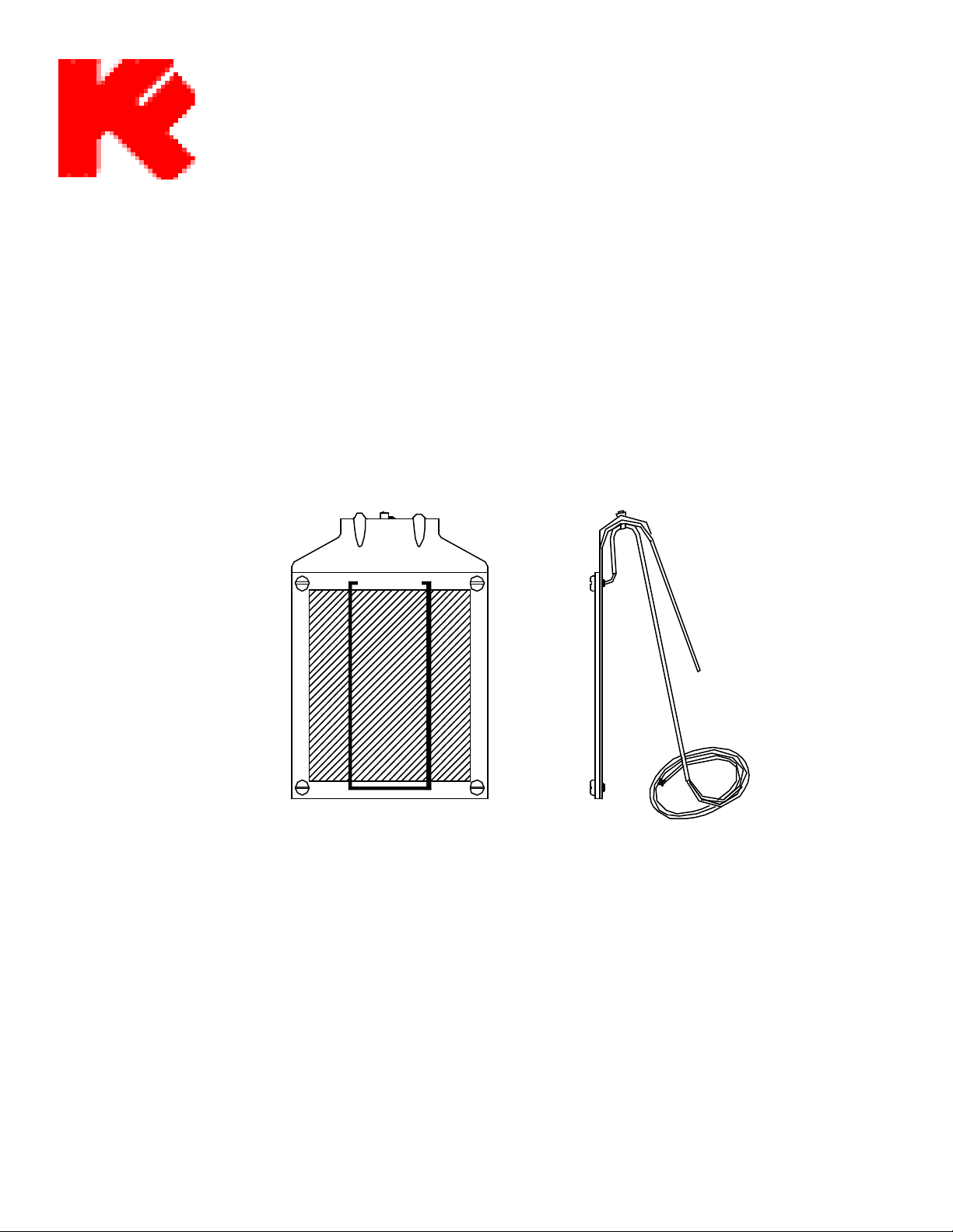
1. ROUTE the Red and Black wires from Solar Cell to Call Box Shell. If the wires are not long enough,
splice two (2) #16 AWG wires (Red and Black) in the Unilet “T”. DO NOT cut black shrink-wrap com-
ing out of Solar Cell.
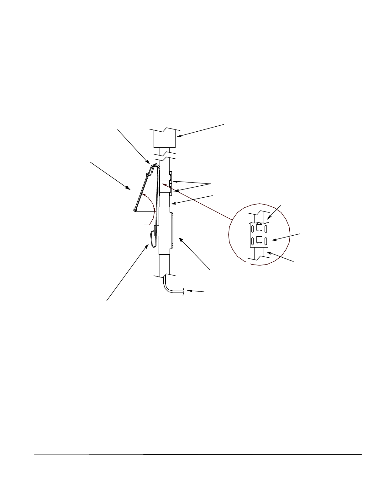
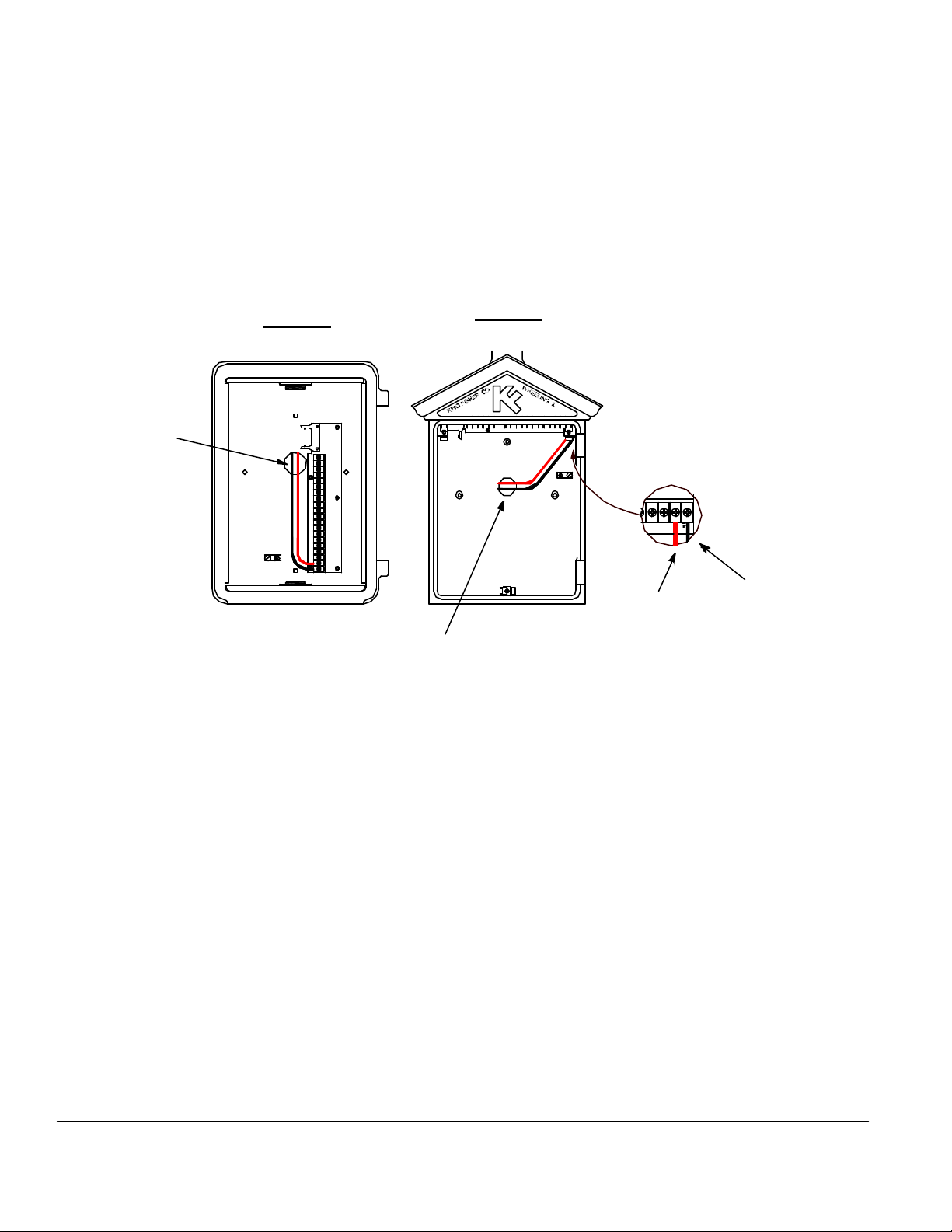
2. CONNECT wires to Terminal Board 66005-1 inside Call Box Shell. Red wire connects to Pin-19
(Charger +). Black wire connects to Pin-20 (Charger -).
TESTING SOLAR CELL
Disconnect Call Box Ribbon Cable from terminal board 66005-1.
Measure the DC Voltage and check polarity across pins 19 (Charger +) and 20 (Charger -). This should be
15 to 18 Volts depending on solar intensity.
Measure the DC current across pins 19 and 20. This should be approximately 40 to 60 mA on a sunny day
and 1 to 9 mA on a cloudy day, depending on solar intensity, cleanliness of glass, and wire length.
CONNECT Ribbon cable to 66005-1.
MAINTAINING SOLAR CELL
Clean Solar Cell face with a damp cotton cloth.
Visually check Solar Cell and Wires for any possible problems.
Perform the above TEST Procedure to verify proper operation.
King-Fisher Company
2350 Foster Ave., Wheeling, IL. 60090-6574
t
847•398•7100 f847•255•1507 e-mail [email protected] Internet: www.kfco.comPage 6Manual 75093-1 03/0119 20
CHARGER
++
SUPV
-
KF1 Shell KF3 Shell
To Solar
Cell
To Solar
Cell
Black (-)
Red (+)