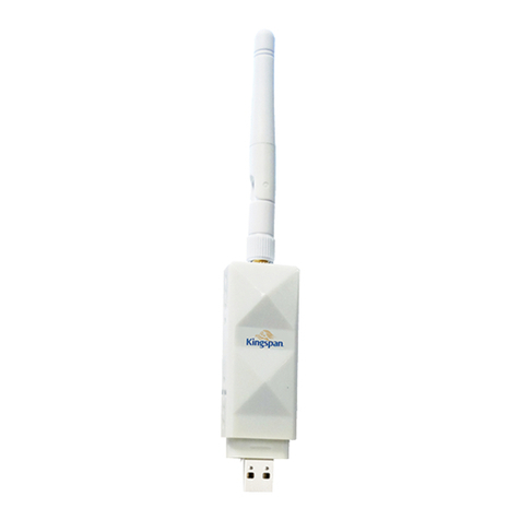
Kingspan TMS300 MULTI-TANK CS Operating manual

GLOBAL TELEMETRY SOLUTIONS
POWERED BY KINGSPAN SENSOR
Page 1
GLOBAL TELEMETRY SOLUTIONS
POWERED BY KINGSPAN SENSOR
User and Installation Manual
WE PUT OUR TELEMETRY
SOLUTIONS TO WORK FOR YOU
TMS300 MULTI-TANK CS

GLOBAL TELEMETRY SOLUTIONS
POWERED BY KINGSPAN SENSOR
Page 2
SUMMARY OF FEATURES
Tank levels via Local screen, embedded webserver, App, online portal or emails
Multi tank level measurement (wireless and wired, up to 18 channels)
Connectivity options via Local Network, GSM (2G/3G) or Internet
Volt free relay outputs for overfll/leak/low level alarms/sudden drop
Remote firmware upgrade
CE certificated
Internal Battery back-up and 12V UPS capability
Historical levels
Levels (litres, percentage, mm)
Alarms (sensor disconnection, leak, high and low alarms, email alerts)
CONTENTS
Page 3
Page 5
Page 6
Page 8
Page 8
Page 9
Page 14
Page 18
Page 27
Page 29
SPECIFICATION
SAFETY PRECAUTIONS
MOUNTING
ELECTRICAL CONNECTION
BATTERY
Dry contact inputs, up to 6
TMS300 OPERATION M<ANUAL
WEB SERVER CONNECTION
WEB SERVER OPERATING MANUAL/CHANNEL WIzARD
SOFTWARE UPGRADE
WALL MOUNT TEMPLATE

SPECIFICATION
GLOBAL TELEMETRY SOLUTIONS
POWERED BY KINGSPAN SENSOR
1. DIMENSIONS
Width: 300mm
Height: 180mm
Depth: 100mm
2. ELECTRICAL AND ENVIRONMENTAL SPECIFICATION
❱Supply voltage: 110 240VAC or 12-24VDC
❱Max input power: 24VA
❱Operating temperature: 0˚C- 40˚C
❱Relay’s max switching current: 5A
3. INPUTS
❱6 channels, 4-20mA with internal 12V DC power supply
—Compatible with any 4-20mA sensor
i.e. relative pressure, ultrasonic etc.
❱Optional wireless module
—433MHz
—Compatible with WATCHMANSONIC
transmitter family
5. RELAY OUTPUTS
Note: The information supplied in this
manual is for guidance only – no part
of this may be used for any agreement,
whether express or implied, or to form
any contract.
4. OUTPUTS
❱ 4-20mA output (only with wireless module)
Note: The alarm relays are 2 contact arrangements which are isolated (volt-free).
These relays may be used to trigger an external bell, warning lamp or digital
communicator (telephone dialler).
Resistive load
Number of relays 2
Contact mechanism DPCO
Max. switching voltage 250VAC, 220VDC
Max switching current 5A
Page 3

GLOBAL TELEMETRY SOLUTIONS
POWERED BY KINGSPAN SENSOR
Page 4
TMS300 is compatible with:
Watchman Sonic 4-20mA waveguide – 019052
Watchman Sonic Waveguide EU -019369
Watchman Alarm Waveguide EU-019371
4-20mA pressure sensor - 004035
Any 4-20mA sensor
Watchman Sonic - 003963 Watchman Sonic EU 004644
Watchman Sonic Alarm – 004030 Watchman Sonic Alarm EU 004645
Watchman Sonic Plus – 002893 Watchman Sonic Plus EU 007041
6. CONNECTIVITY
Embedded Web Server
Connect Sensor
—GSM 2G/3G
—internet (port forwarding required)
—direct connection via ethernet cable
—
—
local network
internet (port forwarding required)
Wi-Fi network (USB Wi-Fi adaptor required)
—
7. SENSORS
8. ADDITIONAL EQUIPMENT

GLOBAL TELEMETRY SOLUTIONS
POWERED BY KINGSPAN SENSOR
Page 5
Note: This installation
procedure is for guidance only,
and its suitability should be
verified by the installer.
INSTALLATION
SAFETY PRECAUTIONS
The following safety precautions are strongly recommended:
Before attempting to install and operate the unit, read the instruction and installation
manual carefully.
Installation and any maintenance should only be carried out by suitably qualified
personnel.
It is recommended that the unit be connected to the mains supply via a suitably rated
isolating switch.
WARNING: When the unit is connected to the mains supply and the cover is open, the
circuits at mains voltage will be exposed. Therefore when installing the unit, ensure all
required connections (including battery connected, if included), are made and covers
replaced before turning on the mains supply. Ensure that all the connections made are
secure. If any maintenance work e.g. installing a new battery, is required ensure that
the unit is isolated from the mains supply before removing the cover. Never leave the
unit unattended if the cover has been removed and the mains supply is connected.
Do not exceed unit ratings as shown on the ratings label.
It is advisable to route mains cables away from low voltage or sensor cables.
Note: For viewing comfort, the unit should be positioned at eye level. The ideal operating
temperature of the unit is (0oC to +40oC). It is always good practice to keep
electronic equipment away from cold, heat and electrical plant, as extremes of
temperature may reduce the lifetime of the device, and heavy electrical loads,
switches, relays or contactors too close to the device may cause electrical and
electro-magnetic interference when switched on or off.

GLOBAL TELEMETRY SOLUTIONS
POWERED BY KINGSPAN SENSOR
Page 6
WALL MOUNT
Drill four holes in the wall, according to the template and insert the wall plugs
Remove the Front Lid by unscrewing two screws
Disconnect the modules
Separate the front cover by unscrewing two screws
Remove the required knock outs from Back Box for the cables to pass through
(always separate front cover before removing the knock outs)
Insert the cable glands
Screw in the Back Box to the wall
Pass the cables through the glands
Mount the Front Cover on the Back Box
Insert the modules
Connect the power supply cable and sensors
Tighten the cable glands
Mount the front lid
MOUNTING
PANEL MOUNT (REQUIRED PANEL MOUNT KIT)
Cut a hole in the panel with the described dimensions, (page 10)
Remove the Front Lid unscrewing two screws
Disconnect the modules
Separate the front cover by unscrewing two screws
Remove the required knock outs from Back Box for the cables to pass through
(always separate front cover before removing the knock outs)
Attach the Panelmount Seal, ensure that it is on the right position
Insert the Back Box into the panel cut out
Attach the four panel mount fixing clips (supplied), to the four studs at either side
of the unit, (page 10).
Tighten the four Panelmount Fixing Screws
Insert the cable glands
Pass the cables through the glands
Mount the Front Cover on the Back Box
Insert the modules
Connect the power supply cable and sensors
Tighten the cable glands
Mount the front lid

GLOBAL TELEMETRY SOLUTIONS
POWERED BY KINGSPAN SENSOR
Page 7
296 mm
169 mm
Area required to be cut out for
Panel mount
168 mm
50 mm
177 mm
Panel mount fixing
clip
Panel mount Fixing
screw
Panel mount fixing
clip Panel mount Fixing
screw
Right side view
168 mm
50 mm
177 mm
Panel mount fixing
clip
Panel mount Fixing
screw
Panel mount fixing
clip
Panel mount Fixing
screw
Left side view
Template, page 29

SETTING UP THE UNIT AND CHANNEL CONFIGURATION
Connecting with Web Server, please see page 14
ELECTRICAL CONNECTION
Note: This device should be properly earthed. Flexible wires simplify connection to the
terminals. All connections should be secure and adequately tightened. It is good practice
to keep mains cables away from sensor cables and other low voltage signal cables.
Supply voltage: 110-240VAC or 12-24VDC
Max input power: 24VA
Operating temperature: 0˚C- 40˚C
Relay’s max switching current: 5A
BATTERY
The battery supplied is a 3.7V Lithium-polymer rechargeable battery and is plugged in but switched OFF.
This should be switched ON after installation. See picture below. This battery is not essential for the sys-
tem operation, but is used in the case of power failure.
The system parameters will remain intact, in the event of a power failure, however all interface options
(Ethernet, screen, keypad) will not function as normal.
It is recommended that the battery is changed every 24 months, in order to maintain good power failure
backup operation. When replacing, ensure that the type of rechargeable battery used is as specified.
(3.7V Lithium-polymer rechargeable battery)
ISOLATE POWER SUPPLY BEFORE OPENING COVER
OFF
ON
Mains
Fuse
Battery switch
GLOBAL TELEMETRY SOLUTIONS
POWERED BY KINGSPAN SENSOR
Channel configuration, please see page 18
Page 8

GLOBAL TELEMETRY SOLUTIONS
POWERED BY KINGSPAN SENSOR
Page 9
TMS300 MULTI-TANK CS OPERATION
In order to fully understand the operation of the unit, this section should be read
carefully.
OK
ESC
Power ON/OFF indicator
Alarm Triggered Indicator
Max. Volume Alarm Hard
Max. Volume Alarm Soft (blinking icon)
Min. Volume Alarm Hard
Min. Volume Alarm Soft (blinking icon)
LAN cable connected and IP obtained
GSM/GPRS signal strength
Buzzer OFF/Alarm muted
Channel OFF
Sensor disconnection

GLOBAL TELEMETRY SOLUTIONS
POWERED BY KINGSPAN SENSOR
Page 10
MAIN MENU
This screen allows user to choose any options available.
To back to MAIN MENU press the key
1. TANKS
These screens allow user to view all the sensor status for each channel, e.g.
Level, Disconnection, Alarms
Press the key to reveal the channel view, use or to change between
channels.
ESC
OK

GLOBAL TELEMETRY SOLUTIONS
POWERED BY KINGSPAN SENSOR
Page 11
2. NETWORK
This screen allows user to set up the Network connection.
User can choose DHCP option or manually enter the IP address.
To set Automatic Network Configuration, use the key to select DHCP and use
the key to select or deselect this option.
- Indicates that the DHCP is OFF.
- Indicates that the DHCP is ON.
Select and use the key to save the settings.
It can take few minutes to save new settings.
3. LCD CONTRAST
This screen allows user to adjust the LCD contrast.
Use to adjust and press the key to confirm.
* To obtain the IP address please contact with your Network Administrator.
OK
OK
OK

GLOBAL TELEMETRY SOLUTIONS
POWERED BY KINGSPAN SENSOR
Page 12
4. LCD BACKLIGHT ON/OFF
This screen allows user to switch ON/OFF ‘AUTO BACKLIGHT’ option.
Use to choose the option and press the key to confirm.
5. BUZZER ON/OFF
This screen allows user to switch ON/OFF internal buzzer sound.
Use to choose the option and press the key to confirm.
*To mute the internal buzzer when alarm activated press any key.
OK
OK
- Backlight will stay ON all the time
- Backlight will switch OFF automatically in approx. 2 minutes if no key has been pressed

GLOBAL TELEMETRY SOLUTIONS
POWERED BY KINGSPAN SENSOR
Page 13
6. WEBSERVER PASSWORD
This screen allows user to reset the webserver ‘admin’ account password.
Use to choose the password and press key to confirm.
7. DEFAULT SETTING
This option will reset all settings to the factory settings.
Password: Unit serial number
OK
* To change the password, user will need to confirm the old one.
Default password is: last 4 digits of unit serial number
Router
Internet
THX Datalogger
Computer Laptop
Laptop
8. 4-20mA OUTPUT
Use to choose the channel and press the key to confrm.
OK

GLOBAL TELEMETRY SOLUTIONS
POWERED BY KINGSPAN SENSOR
Page 14
WEBSERVER CONNECTION
To connect with unit’s embedded Web Server, connect unit to the network (switch,
hub, router etc.) using Ethernet CAT-5 cable or directly to the network adapter on
your computer and open a web browser - Windows Internet Explorer (version 8.0 or
higher) or Firefox. Input the unit’s IP address (default -192.168.0.2)
1. NETWORK CONNECTION (please contact with your network administrator)
Router
Internet
Computer Laptop
Laptop
* Internet - port forwarding required

GLOBAL TELEMETRY SOLUTIONS
POWERED BY KINGSPAN SENSOR
Page 15
2. DIRECT CONNECTION
Check the MTMS network settings.
Use the keypad and navigate to the appropriate screen
MAIN MENU->NETWORK
Router
Internet
THX Datalogger
Computer Laptop
Laptop
Note: The network setting may vary between devices.
Connect MTMS to the computer using Ethernet cable.
Change the computer’s network settings

GLOBAL TELEMETRY SOLUTIONS
POWERED BY KINGSPAN SENSOR
Page 16
DEFAULT USERNAME AND PASSWORD:
Administrator:
Username: admin
Password: last 4 digits of the units serial number
This password can be changed, see page 11
User: (only for viewing levels)
Username: user
Password: last 4 digits of the units serial number
This password cannot be changed.
Note: The last octet of the computer’s
IP address (“60” in this example)
should be different than the last octet
of the MTMS IP address (“57” in this
example). The subnet mask and default
gateway should be identical.

GLOBAL TELEMETRY SOLUTIONS
POWERED BY KINGSPAN SENSOR
Page 17
3. Wi-Fi CONNECTION (USB Wi-Fi ADAPTER REQUIRED)
❱
Router
Internet
Computer Laptop
❱
❱
The USB Wi-Fi adaptor lets you create a WiFi network from a unit
to allow connection with webserver on all of your wireless devices
including tablets, laptops / Ultrabooks and smartphones.

GLOBAL TELEMETRY SOLUTIONS
POWERED BY KINGSPAN SENSOR
Page 18
CONFIGURING SENSOR AND TANK DETAILS
1. CHANNEL WIZARD
This screen allows user to configure sensor and tank details.
STEP 1
Choose the channel, set name and click NEXT
STEP 2
Choose the sensor, fill in the required informations and click NEXT
*Watchmansonic avaiable only with RF module

GLOBAL TELEMETRY SOLUTIONS
POWERED BY KINGSPAN SENSOR
Page 19
- 4-20mA Pressure Sensor
-4-20mA Waveguide (Watchmansonic)
-4-20mA utrasonic sensor
-Watchmansonic (only with RF module)
-Dry contact
Enter the Sonic Height.
Sonic Height - distance between the base of sensor
to bottom of the tank
Enter the Sonic Height.
Sonic Height - distance between the base of sensor
to bottom of the tank

GLOBAL TELEMETRY SOLUTIONS
POWERED BY KINGSPAN SENSOR
Page 20
STEP 3
Choose the tank shape and fill in dimensions.
Click ‘Calculate’ to obtain tank capacity or type in manually.
*To add the strapping table, choose Irregular tank and click ‘Next’
Fill in the table or upload file with existing strapping table.
Other manuals for TMS300 MULTI-TANK CS
1
Table of contents
Other Kingspan Measuring Instrument manuals
Popular Measuring Instrument manuals by other brands

ION
ION DIGITAL ALTIMETER user manual

Agilent Technologies
Agilent Technologies E4406A VSA Series Programmer's guide

ADTEK
ADTEK MWH-8W manual

PCB Piezotronics
PCB Piezotronics ICP J356A44 Installation and operating manual

Nedo
Nedo ACCEPTOR 2 digital operating instructions

Befaco
Befaco Crush Delay user manual