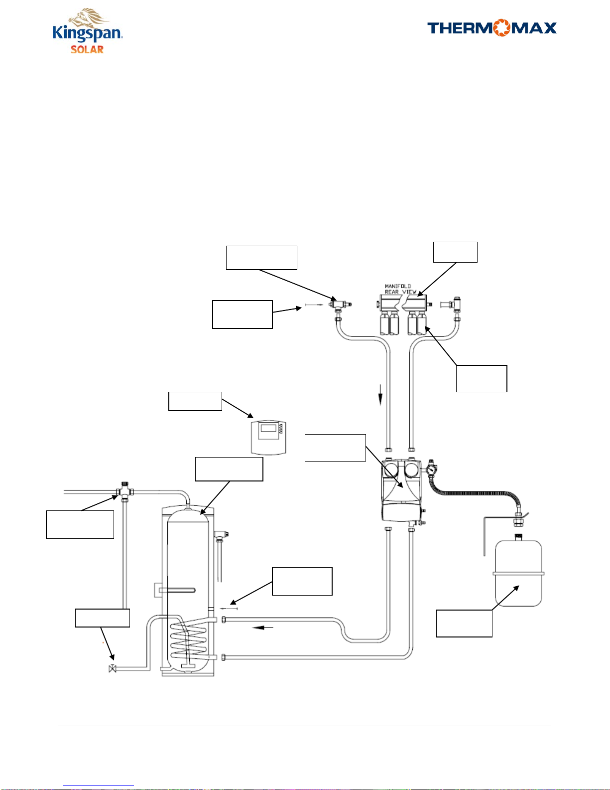
Kingspan Solar System Overview
Solar hot water systems should be designed and sized correctly before commencing the installation. Proper design will
insure that a system is correctly sized to provide many years of optimized performance, contributing a significant
percentage of the annual domestic hot water demand of a building. A supplementary heating system such as oil or gas
boiler, heat pump, electrical immersion heater or wood boiler is required for periods where the solar cannot make
enough heat to meet the demand.
This guide covers the installation of solar domestic hot water systems. For larger and more complex systems Kingspan
provides a system design service to its customers and technical design consultants. Consult with your distributor for
more information on this service.
This guide will illustrate and explain how a system should be installed to conform to the Kingspan Solar guidelines for
the Thermomax product models.
The solar energy system described by this manual, when properly installed and maintained, meets the minimum
standards established by the SRCC. This certification does not imply endorsement or warranty of this product by SRCC.
Important Pre-Installation Information
The installation shall conform to all federal, state and local regulations, codes, ordinances and standards governing solar
water heating system installations, and the contractor shall adhere to sound building safety and trade practices. Special
consideration must be given to building code requirements for the penetration of structural members and fire rated
assemblies. Any penetrations shall not allow vermin infiltration.
The installer should consult www.osha.gov for the 2001 Code of Federal Regulations, Chapter 29 Part 1926 Safety and
Health Regulations for Construction prior to undertaking the installation.
The installer must have proper safety equipment when working on elevated surfaces, as per OSHA requirements. Fall
protection equipment must be used with the proper training.
The homeowner and installer must confirm the location of all roof mounted components in advance of the installation.
The solar panels must be located in a structurally sound area of the roof that will not be shaded for the majority of the
day during all times of the year. Adjacent buildings and trees should be checked for possible winter shading before
commencing the installation.
Before the installation the installer shall inspect the condition of the roof and notify the homeowner of any existing roof
damage or necessary repairs.
The system has several safety features that will not allow the system to go outside of the maximum design temperature
and pressure requirements. The controller will monitor the system and insure that the temperatures do not rise to
extremes. In addition, a pressure relief valve on the solar loop and a temperature and pressure relief valve are provided
on the tank. The expansion tank on the solar loop will maintain the correct pressure, regardless of temperature. Check
with local regulations to see if an expansion tank is required on the domestic water side of the system. Under no
circumstances during the installation should these mechanisms be deleted, or overridden, as this could cause a severe
safety concern.
Any components that could be exposed to public traffic and are above 140°F should be insulated. Any other area that
may get above 140°F within the system should be labeled as such.
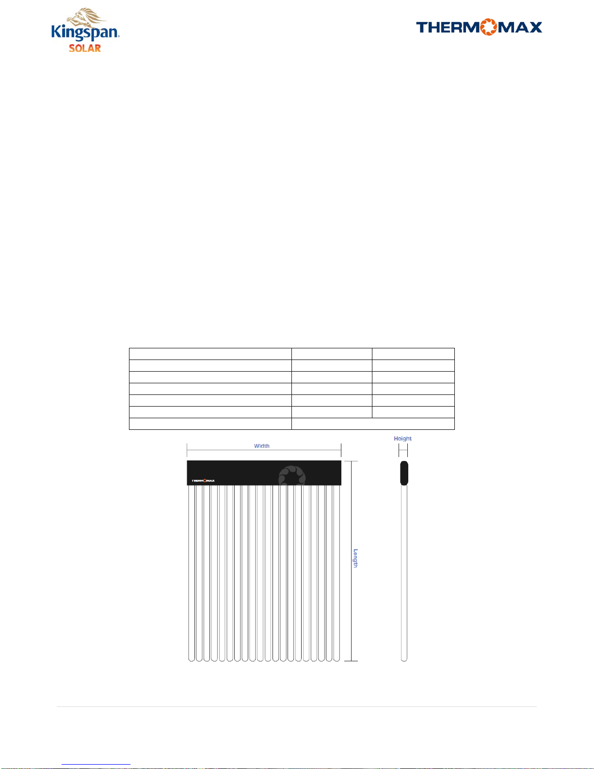
Tube and manifold boxes should be transported horizontally.
Care should be taken when opening boxes to prevent scratches or sudden shocks to the glass.