K115sm1e1.doc
1-3
1. 2 Specifications
Subject Specification
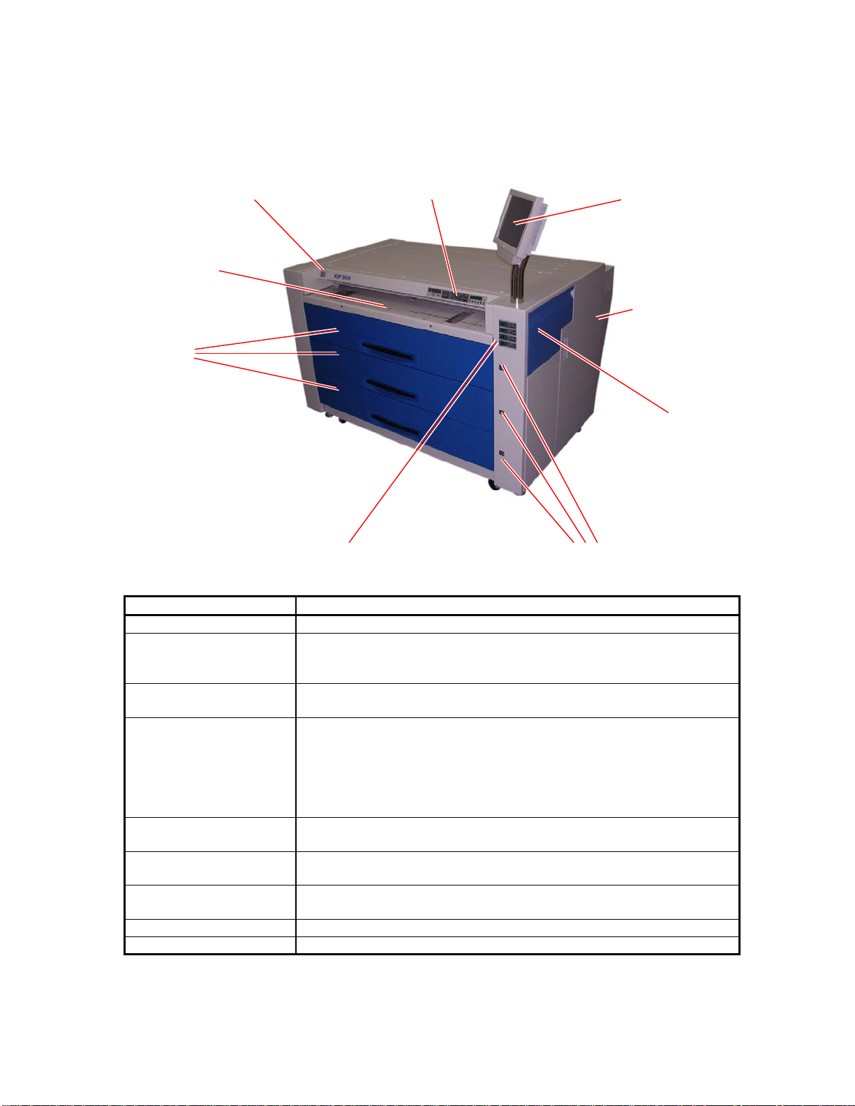
Model KIP 9000
Type Console
Printing method LED Array Electro Photography
Photoconductor Organic Photoconductive Drum
Print speed 240mm / second (11 A0 or E /minute - 22D/minute)
Exposure method LED Print Head
Resolution 600dpi x 600dpi
Print width Max : 914mm (36 inches)
Min : 297mm (11 inches)
Print length Max : Plain paper 6m (19.7’) with A0 or 36” wide
Tracing paper A0 / 48 inch
Film A0 / 48 inch
NOTE : Longer print than the above specified maximum lengths
is available. However, KIP does not guarantee any result
including image quality and media feeding if the print is
longer than the above specified lengths.
Min 210mm (8.5”)
Warm up time Shorter than 6 minutes
(At 23 degrees centigrade, 60% RH and 230V)
First print time Shorter than 12 seconds (A0 / E)
Fusing method Heat roller fusing
Development Contact type mono component non-magnetic development system
(One toner cartridge contains 500g.)
Charging method Corona
Media feeding method Automatic roll feeding (4 Roll Decks)
Manual bypass feeding
NOTE : Multiple cut sheet feeding (50 sheets max) is available
when the size is narrower than A2 (594mm) or 24”.
Transfer method Corona
Separation method Corona and LED
Input power 220 - 240V (+6% / -10%), 16A and 50/60Hz in U.S.A. and Europe
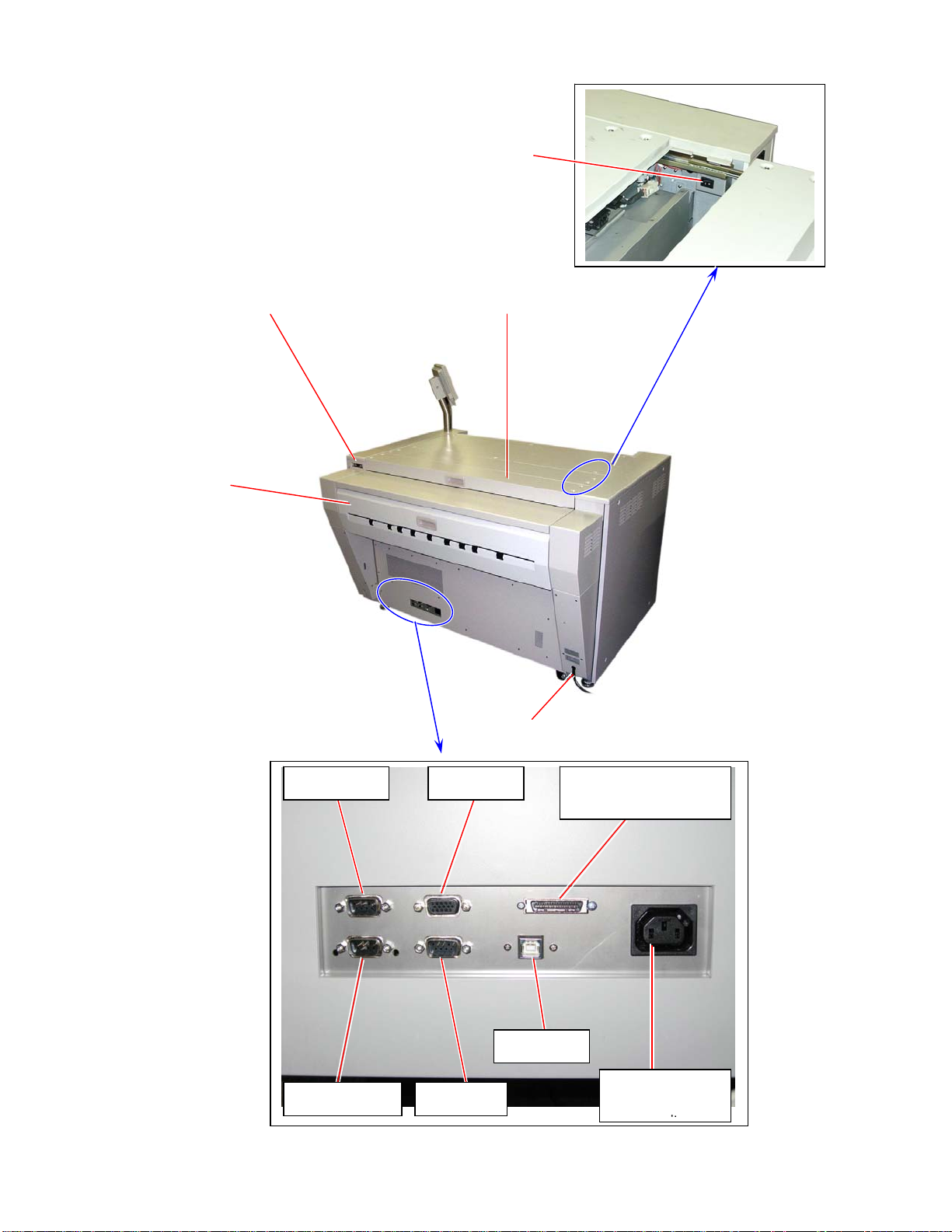
Interface KIP Interface 8 (LVDS)
USB2.0 (5VDC max)
RS-232C (12VDC max)
Maximum power
consumption When 230V, 50/60Hz and Dehumidify Heater is ON
Stand by 0.9 Kwh
Printing 3.0 Kwh
Warm up 3.5 Kwh
Acoustic noise Less than 70db (Printing) NOTE : Impact noise is excluded.
Less than 55db (Stand by)
Ozone Less than 0.05ppm (Average of 8 hours)
Dimensions 1360mm (Width) x 980mm (Depth) x 1265mm (Height) (54x39x50)
Weight About 400kg (880lbs)
Media Specified media
Plain paper 18 - 24# 70 - 90g/m2
Tracing paper 18 - 24# 70 - 90g/m2
Film 100 micrometer (4mil) or thinner..