4
INSTALLATION
INSTALLATION
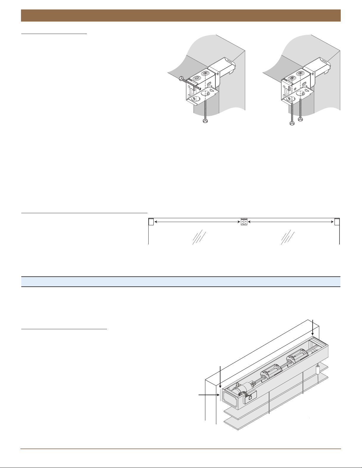
Attach the End Brackets
With inside or ceiling mounts, attach the two end brackets
flush against the sides of the window casement or to the
ceiling. Choose the most appropriate of the following
mounting methods:
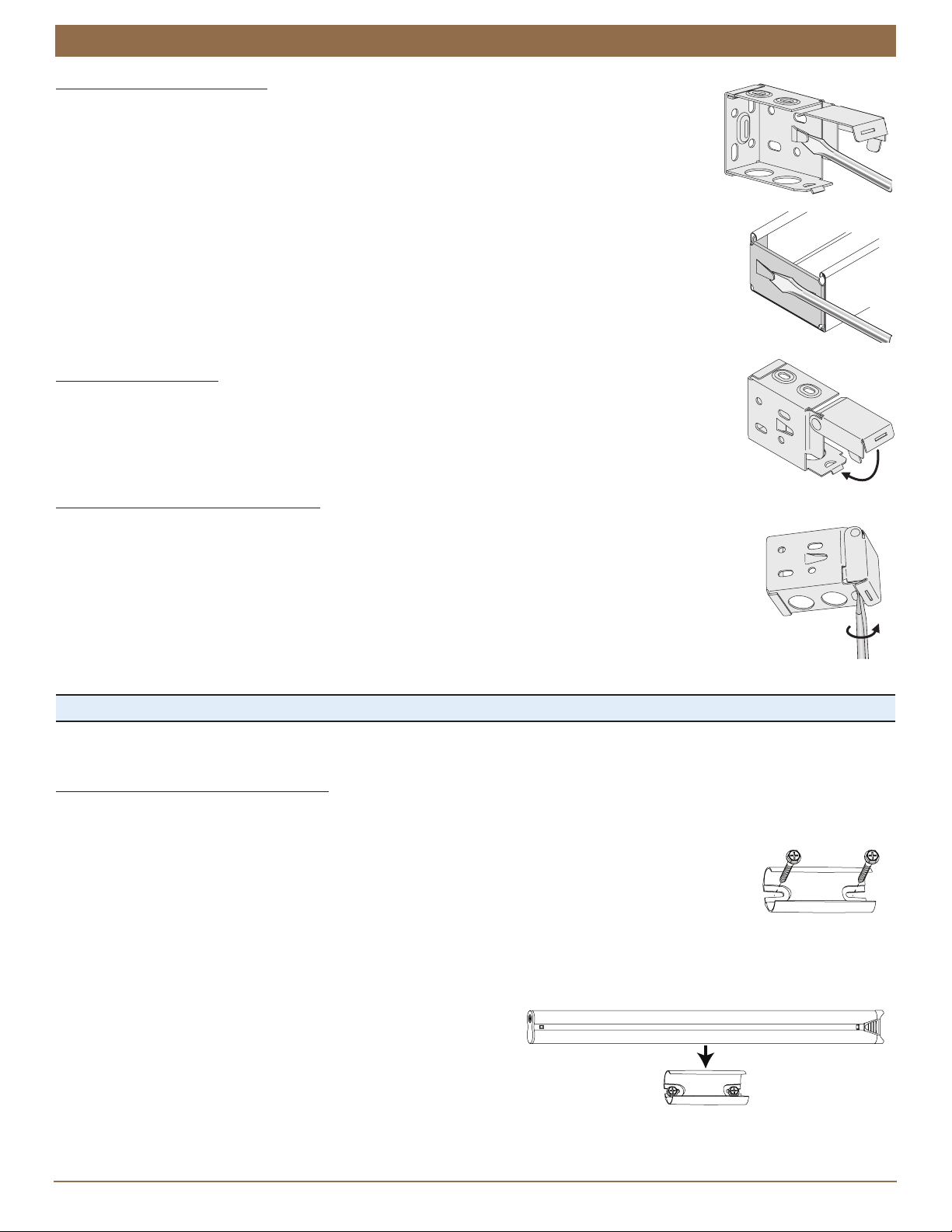
Inside mount only (Side/Top Mount): Mount the end
brackets with one screw through a side hole and one
screw through a top hole, as shown in the first image
to the right.
Inside mount only (Side Mount): Mount the end
brackets with two screws through diagonal side holes.
Inside or ceiling mount (Top Mount): Top mount the
end brackets with screws through the two top holes, as
shown in the second image to the right.
Ceiling mount only: If the end brackets are flush with
the back wall, attach them with one screw through a
top hole and one screw through a rear hole.
Use a
3
⁄
32
" drill bit to drill holes for the mounting screws.
Attach the end brackets using the screws provided.
IMPORTANT: The front edges of the end brackets must align.
NOTE: For blinds with 2
1
⁄
2
" slats, spacer blocks are used with inside mounts to position the end brackets a minimum of
3
⁄
8
"
away from the glass. The spacing prevents the slats from rubbing the glass when they are tilted open.
Attach the Intermediate Brackets (If Required)
Evenly space the intermediate bracket(s)
between the two end brackets.
Adjust spacing if needed to avoid
interference with internal headrail
mechanisms.
Attach the intermediate bracket(s) with two screws through diagonal top holes.
IMPORTANT: The rear of the end brackets and intermediate bracket(s) must align.
Proceed to “STEP 3 — Install the Blind” on page 6.
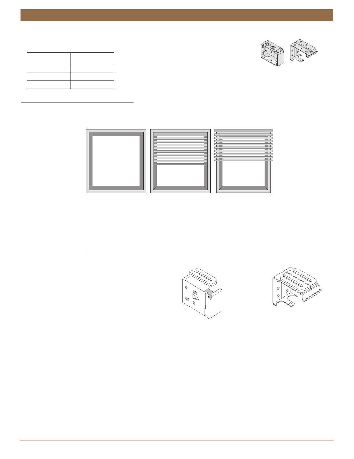
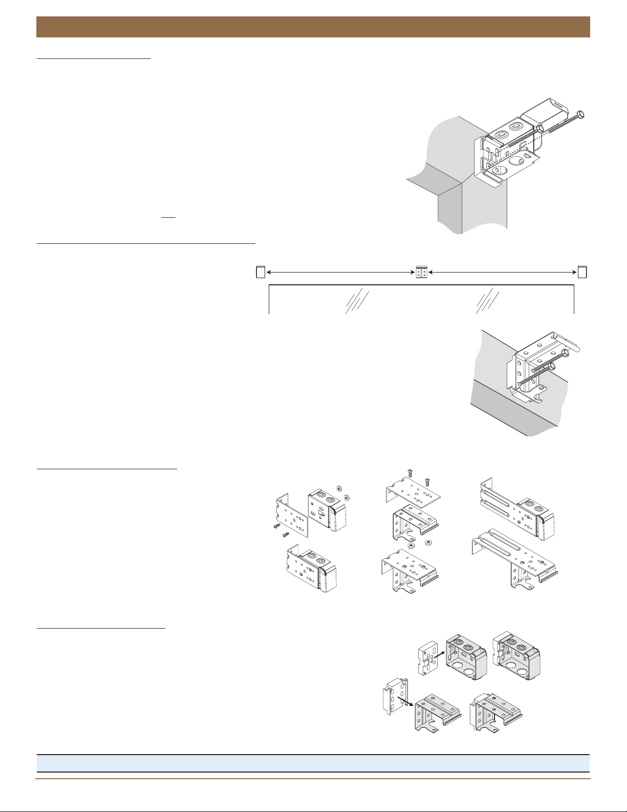
Mount the Installation Brackets — Outside Mount
To attach the end brackets, a flat vertical surface of at least 1
3
⁄
4
" is required for 2" and 2
1
⁄
2
" slat sizes.
Mark the End Bracket Locations
Mark where the ends of the headrail will be located.
Center the headrail over the window opening at the desired height.
Use a pencil to lightly mark each end of the headrail.
Alternatively, measure the width of the headrail and use that
width to mark the headrail end points over the window opening.
Make a second mark
1
⁄
4
" to the outside of the headrail
end marks. The outer marks are where the outside
edges of the end brackets will be located.
Side/Top
Mount
Top Mount
Intermediate
Bracket
End
Bracket
End
Bracket
Space Evenly Space Evenly
Mark
Measure and Mark
1
∕
4
"Out from
Ends of Headrail
Mark