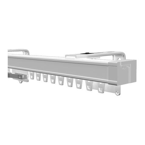
Kirsch Vertical Blinds Series User manual

Note: These are the standard versions of the primary Kirsch® logos. These standard
versions are used everywhere, except when the width of the logo is larger than 2" in
print materials or 250px in digital formats. For use at larger sizes, use the alternate
artwork provided (file named “..._ForLargeSizes_...”).
Vertical Blinds Collection
Installation Instructions
GETTING STARTED
Product View ................................................................................................................................................................ 1
Tools and Fasteners Needed ....................................................................................................................................... 2
INSTALLATION
Installation Overview ................................................................................................................................................... 2
Valance Assembly ......................................................................................................................................................... 3
Mount the Installation Brackets — Inside Mount ..................................................................................................... 5
Mount the Installation Brackets — Outside Mount ................................................................................................. 6
Install the Vanes ........................................................................................................................................................... 7
Attach the Universal Cord Tensioner (Cord Loop Units Only) ................................................................................ 8
Cord Adjustment (Cord and Chain Only) .................................................................................................................. 8
OPERATION
Blind Operation ............................................................................................................................................................. 9
CARE
Removing the Headrail (If Necessary) ..................................................................................................................... 10
Removing the Vanes (If Necessary) .......................................................................................................................... 10
Cleaning Procedures .................................................................................................................................................. 10
CHILD SAFETY ............................................................................................................................................................ 11
Warning ....................................................................................................................................................................... 11
Cord Loop Shades ...................................................................................................................................................... 11
WARRANTY ................................................................................................................................................................. 12
Rev. A 9/3/19

1
GETTING STARTED
Product View
Outside Mount
A
djustable Bracket
Inside Mount
Mounting Clip
Headrail
Cord and
Wand Control
System
Vanes

2
GETTING STARTED
Thank you for purchasing the Kirsch®Vertical Blinds Collection. With proper installation, operation, and care, your new shades will
provide years of beauty and performance.
Please thoroughly review this instruction booklet and the enclosed packing list before beginning the installation.
Tools and Fasteners Needed
■ Flat blade and Phillips screwdrivers
■ Level (laser level is recommended)
■ Measuring tape and pencil
■ Power drill,
3
⁄
32
” drill bit, and
1
⁄
4
” hex drive
In addition, you will need fasteners designed to work with your specific mounting surface(s).
■ #6 Hex Head Screws (Provided). Two 1
1
⁄
2
" screws are provided per installation bracket.
■ Speed Nuts and Screws (Provided). Extension brackets come with speed nuts and screws.
Installation Overview
➤ The number of installation brackets required varies depending on the
shade width, as shown in the table.
Mounting Types and Window Terminology
If the installation brackets are mounted correctly, the rest of the installation process follows easily. To prepare for this important
first step, review the mounting types and basic window terminology illustrated below.
■ Refer to the appropriate page below based on your order:
➤ If your Blind has a Valance — Page 3
➤ Inside Mount — Page 5
➤ Outside Mount — Page 6
Speed Nuts
and Screws
(Provided with Each
Extension Bracket)
#6 x 1
1
⁄
2
"
Hex Head Screws
(Provided)
Blind
Width
Brackets
Required
15" – 48" 2
48
1
/
8
" – 72" 3
72
1
/
8
" – 96" 4
96
1
/
8
" – 120" 5
120
1
/
8
" – 144" 6
144
1
/
8
" – 168" 7
168
1
/
8
" – 192" 8
192
1
/
8
" – 216" 9
216
1
/
8
" – 240" 10
240
1
/
8
" – 264" 11
264
1
/
8
" – 288" 12
288
1
/
8
" – 300" 13
Collectively, the sill and
jambs are called the
“window casement.”
Molding (or Wall)
Head Jamb
Sill (or Floor)
Jamb Jamb
Inside Mount
Blinds fit within
window opening.
Outside Mount
Blind mounts outside
window opening.

3
INSTALLATION
INSTALLATION
Valance Assembly
Please refer to the section below for your valance type.
If you didn’t order a valance, proceed to “Mount the Installation Brakets - Inside Mount” on page 5 or
“Mount the Installation Brakets - Outside Mount” on page 6 based on the mounting option ordered.
Dust Cover Valance Assembly
Single-Tiered Closed Corner
■ Cut a fabric insert for the valance and each valance return 1” longer at each end than the valance and valance return width.
■ Center the fabric insert in the valance and wrap the excess on each side around to the back of the valance.
■ At one end, hold the fabric insert in place with a corner clip.
■ At the opposite end, pull the fabric insert tight and secure it in place with another corner clip.
■ Center each valance return fabric insert and wrap the excess on each side around to the
back of the valance return.
■ Attach the valance return to the valance using the already attached corner clip.
■ At the opposite end of the valance return, pull the fabric insert tight and secure it in
place with a valance return clip.
■ Repeat the previous 4 steps for the other valance return.
IMPORTANT: Vinyl inserts should be cut flush with the ends of the valance and valance
returns. Secure vinyl in place with the corner clip and valance return clips.
Proceed to “Mount the Installation Brakets - Inside Mount” on page 5 or
“Mount the Installation Brakets - Outside Mount” on page 6 based on the mounting option ordered.
Single-Tiered Open Corner (Fabric Only)
■ Cut a fabric insert long enough to wrap around the corner and over the entire
return plus at least 1” excess at each end.
■ Attach the corner clip and valance returns.
■ Insert the fabric into the valance, wrap it through the corner clip and into the valance
return.
IMPORTANT: Leave extra fabric at the other end of the fabric insert to be able to
wrap around the other valance return.
■ Wrap excess fabric around the end of the valance return and secure it with a
valance return clip.
■ Repeat steps 3 and 4 for the other valance return.
Proceed to “Mount the Installation Brakets - Inside Mount” on page 5 or
“Mount the Installation Brakets - Outside Mount” on page 6 based on the mounting option ordered.
Corner
Clip
Valance
Return
V
alance
Valance Return
Clip
Fabric
Insert
Corner
Clip
Valance
Return
Valance
Fabric
Insert
Valance Return
Clip

4
INSTALLATION
INSTALLATION
Single-Tiered Round Corner
■ Install the round valance corners onto each end of the valance.
■ Install the valance returns onto each end of the round valance corners.
■ Cut the fabric insert 4” longer than the total length of the valance plus both returns.
NOTE: Vinyl inserts should be cut flush with the ends of the valance returns. Secure vinyl in place
with the valance return clips.
■ Place the fabric insert into the clear lips of the valance, continuing around the molded valance
corner and through the valance return.
■ Wrap excess fabric around the end of the valance return and secure it with a valance return clip.
■ From the other end of the fabric insert, pull the fabric tight, repeating the previous 2 steps.
■ Attach the clear corner caps onto the valance corners, top and bottom.
■ Use a #4 1/2” screw to secure each valance return onto the dust cover valance surface.
Proceed to “Mount the Installation Brakets - Inside Mount” on page 5 or
“Mount the Installation Brakets - Outside Mount” on page 6 based on the mounting option ordered.
Round Valance
Corner
Valance
Return
Valance
Fabric
Insert
Clear Corner
Caps
Valance
Return Clip
Dust
Cover

5
INSTALLATION
INSTALLATION
Mount the Installation Brackets — Inside Mount
■ Mark 2” to 4” in from each jamb. Measure and mark the underside of the dust cover, if ordered.
➤ If more than two installation brackets came with your order, space additional bracket(s) evenly in 24” to 30” intervals
between the end brackets and mark their location. Mount into wood whenever possible.
IMPORTANT: Allow ½” clearance between vane and window.
Install Mounting Clips
■ Drill the screw holes using a 3∕32” drill bit.
WARNING: Product is heavy. Mount into wood/metal studs or into concrete with
concrete anchors. Drywall anchors are not recommended.
➤ If you did not order a valance, drill directly into the ceiling/head jamb.
➤ If you ordered a dust cover valance, drill through the rear groove of the dust cover
valance then into the ceiling/head jamb.
■ Attach the mounting clip using the screws provided.
➤ Hold the valance in position, the screw will go (through the valance, if ordered)
into the ceiling/head jamb.
■ Center the headrail underneath the mounting clips.
■ Tilt the headrail and insert it into the front edge of the mounting clips.
Pull forward, then roll the headrail back toward the rear of the blind.
Push up and snap into place.
Proceed to “Install the Vanes” on page 7.
2 to 4" 2 to 4"
30" Maximum 30" Maximum
Rear
Groove
Dust Cover
Valance
Mounting
Screw
Mounting
Clip
Mounting
Clip
Side
View
Wall
Ceiling/Head Jamb
21/4"
41/4"
Valance
(Optional)
1/2"
Vane
31/2"
Tilt and
Pull F
orward
Roll Back
Rear Tab
Vertical Track Headrail
Push Up

6
INSTALLATION
INSTALLATION
Mount the Installation Brackets — Outside Mount
■ Mark 2” to 4” in from each jamb.
➤ If more than two “L” installation brackets came with your order, space additional bracket(s) evenly in 24” to 30” intervals
between the end brackets and mark their location. Mount into wood whenever possible.
➤ Adjust mounting clips to allow 1/2” clearance between the vane and the wall (i.e. 21/4” for 31/2” vane).
■ Drill the screw holes using a 3∕32” drill bit.
WARNING: Product is heavy. Mount into wood/metal studs or into concrete with concrete anchors. Drywall anchors
are not recommended.
■ Attach the brackets using the screws provided.
■ Center headrail underneath mounting clips.
■ Tilt the headrail and insert it into the front edge of the mounting clip. Pull and roll the headrail up toward the rear of the blind
and snap into place.
2 to 4" 2 to 4"
30" Maximum 30" Maximum
Tilt and
Pull F
orward
Roll Back
Vertical Track Headrail
Push Up
Rear
Tab

7
INSTALLATION
INSTALLATION
■ If a valance is included, “snap” on a valance hanger next to each “L” bracket.
■ Center the valance in relationship to the headrail and slide it into the valance hangers.
Install the Vanes
■ Determine the desired light/view direction.Rotate the vane hooks so the slot between the long and the short prong is facing
you.
■ Push the vane into the hook until it “snaps” into place.
Mounting
Clip
“L” Bracket
Side
View
Wall
Valance Hanger
Valance
(Optional)
31/2"
21/4"
1/2"
41/4"
Vane
Finished
Side
Top View
Finished
Side
Light Diffusion
into Room
Light Diffusion
into Room
Light Source (Sun)
Light Source (Sun)
Short
Prong
Long
Prong
Carrier

8
INSTALLATION
INSTALLATION
Attach the Universal Cord Tensioner (Cord Loop Units Only)
Before doing anything, you must first slide the cord tensioner to the bottom of the cordloop.
■ Insert a small screwdriver, punch, or awl through the screw hole at the bottom of the cord
tensioner.
■ Move the screw hole down to the indicator line to release the safety mechanism.
■ Slide the cord tensioner down to the bottom of the cordloop.
■ Attach the cord tensioner according to the instructions provided with the Universal Cord
Tensioner Installation Kit.
WARNING: It is imperative that the cord tensioner be properly secured to the wall or window frame to
reduce children’s access to the cord loop. Young children can strangle in cord loops. They can also wrap cords
around their necks and strangle.
CAUTION: The unit will not operate properly unless the cord tensioner is secured. A Universal Cord Tensioner
Installation Kit has been included with your unit. Follow the instructions in the kit to correctly secure the cord
tensioner.
Cord Adjustment (Cord and Chain Only)
To reduce cord length on a Side Draw Blind:
■ Open the blind.
■ Release the cord tensioner by removing the screws.
■ Locate the cord knot in the front of the lead carrier.
■ Pull the cord to the desired length.
■ Tie a double knot.
■ Re-install the cord tensioner with the screws.
■ Test for proper cord tension.
■ Cut the excess cord.
To reduce cord length on Center Draw Blinds:
■ Release the cord tensioner by removing the screws.
■ Place the blind in the closed position.
■ Locate the cord ends in the front of the lead carrier.
■ Select the cord knot that adjusts the cord length only; if carrier movement is observed, select the other cord.
CAUTION: Cutting the wrong cord will cause irreparable damage.
■ Pull the cord to the desired length.
■ Tie a double knot.
■ Re-install the cord tensioner with the screws.
■ Test for proper cord tension.
■ Cut the excess cord.
Indicator
Line
Universal
Cord
Tensioner
Side Draw Carriers
in the Open P
osition
Cord Knot
Center Draw Carriers
in the Closed P
osition
Cord Knot

9
INSTALLATION
OPERATION
Blind Operation
Cord and Chain Operated
■ Traversing. Use the pull cords attached to the cord tensioner to open and close the blind (black arrows).
■ Tilting. Use the tassels and chains to rotate the vanes open or closed (gray arrows).
Cord and Wand Operated
■ Traversing. Use the pull cords attached to the cord tensioner to open or close the vanes (black arrows).
■ Tilting. Twist the safety wand to open or close the vanes (gray arrows).
IMPORTANT: Do not over torque the wand. It can cause the louvers to kick out at the bottom of the blind and cause the
louvers to look misshapen.
■ Pull the rear cord to lower the shade.
■ Pull on the front cord to raise the shade
■ IMPORTANT: If the cord tensioner moves up the cord, you have not secured it to the wall or window frame. You must do so
for the shade to operate properly. See the instructions that came in the cord tensioner installation kit.
Side Stack
Split Stack
Side Stack
Split Stack

10
INSTALLATION
CARE
Removing the Headrail (If Necessary)
■ To remove the headrail, locate the rear tab on the mounting clip.
■ Push up on the rear tab to release the headrail.
Removing the Vanes (If Necessary)
■ Push up on the vane.
■ Gently open the vane hook by inserting a ‘credit card’ sized piece of rigid plastic between the vane and the long prong of the
vane hook.
■ Carefully remove the vane.
Cleaning Procedures
Dusting
■ Regular light dusting with a feather duster is all the cleaning that is needed in most circumstances.
Vacuuming
■ Use a hand-held vacuum with low suction for more thorough dust removal.
Spot-Cleaning
■ Prepare a solution of warm water and a mild detergent.
■ Dampen a clean cloth in the solution and wring it out.
■ Dab the spot with the dampened cloth until it is gone.
CAUTION: Vertical fabrics should not be spot-cleaned or immersed in water.
Compressed Air
■ You can use compressed air or a hair dryer (cool setting) to blow the dust o your valance.
Tilt to
Remove
Rear Tab
Vertical Track Headrail
Push Up

11
INSTALLATION
CHILD SAFETY
For more safety information call 1-844-547-7242.
WARNING
Young children can STRANGLE in cord loops. They can also wrap cords around their necks and STRANGLE.
■ Always keep cords out of the reach of children.
■ Move cribs, playpens and other furniture away from cords. Children can climb furniture to get to cords.
Cord Loop Panels
■ Attach the cord tensioner on the cord loop to the wall or window casement. See “Attach the Universal Cord
Tensioner (Cord Loop Units Only)” on page 5. This can prevent children from pulling cord loops around their
necks.
■ Kirsch provides a cord tensioner installation kit with instructions for attaching the cord tensioner. For the
shade to operate properly, the cord tensioner must be correctly mounted andsecured.
■ Fasteners provided in this kit may not be appropriate for all mounting surfaces. Use appropriate anchors for
mounting surface conditions.
■ Only Kirsch supplied cord tensioners and hardware should be used. Replacement parts may be obtained by
contacting the Kirsch Consumer Support at 1-844-KIRSCH2 (844-547-7242).

12
WARRANTY
Warranty
© 2019 Kirsch Custom Window Coverings. All rights reserved. All trademarks used herein are the property of Kirsch or their respective owners. 09/19
Kirsch® is pr
oud to extend a 10-year limited warranty on all Kirsch Custom Window Covering products. This is part
of our commitment to providing the highe
st quality products, which has been our continued tradition since 1907.
COVERED
by a 10-Year
Limited Warranty
•
Kirsch Custom Window Covering products are
covered for defects in materials, workmanship
or failure to operate for 10 years from the date
of purchase (unless a shorter period is provided
below), provided that the original retail purchas-
er continues to own the product.
•
All internal mechanisms.
•
Fabric delamination.
•
Components, brackets and operational cords.
•
Repairs and/or replacements will be made with
like or similar parts or products. Fabric style, color
or components may vary depending on original
purchase date.
•
Kirsch automation components are covered for
5 years from the date of purchase.
NOT COVERED
by a 10-Year
Limited Warranty
• Any conditions caused by normal wear and tear.
• Abuse, accidents, misuse or alterations to the
product.
• Exposure to the elements (sun damage, wind,
water/moisture, salt air) and discoloration or
fading over time.
• Normal maintenance associated with motors
and related accessories including, but not limited
to, recharging and replacement of batteries.
• Failure to follow our instructions with respect
to measurement, proper installation, cleaning
or maintenance.
• Shipping charges, cost of removal and reinstalla-
tion.
Kirsch (o
r its licensed fabricator/distributor) will repair or replace the product or components found to be defective.
TO
OBTAIN WARRANTY SERVICE:
•
Contact your original dealer (place of purchase) for warranty assistance.
•
Contact Kirsch at 844-KIRSCH2 (844-547-7242) for technical support, certain parts free of charge, for assis-
tance in obtaining warranty service or for further explanation of our warranty.
NO
TE: In no event shall Kirsch or its licensed fabricator/distributor be liable or responsible for incidental or conse-
quential damages or
for any other indirect damage, loss, cost or expense. Some states do not allow the exclusion
or
limitation of incidental or consequential damages, so the above exclusion or limitation may not apply to you. This
warr
anty gives you specific legal rights, and you may also have other rights which vary from state to state.
10-
Year Limited Warranty
Table of contents
Other Kirsch Window Blind manuals

Kirsch
Kirsch Banded Shade Automation III User manual

Kirsch
Kirsch Alternative Wood Blinds Series User manual

Kirsch
Kirsch Roller & Screen Shade User manual

Kirsch
Kirsch Architrac 94001 User manual

Kirsch
Kirsch Wood Blinds Tilt Automation III User manual

Kirsch
Kirsch Alternative Wood Blinds User manual

Kirsch
Kirsch Cellular Shade Series User manual

Kirsch
Kirsch Basic Faux Wood User manual
Popular Window Blind manuals by other brands

VENETA
VENETA 65101-50725-D How to install

rollease acmeda
rollease acmeda ZIPSCREEN installation manual

Draper
Draper FLEXSHADE 2 Installation & operation instructions

MHZ
MHZ R 03 Installation and operating instructions

Style selections
Style selections 978840204 Assembly instructions

Gardinia
Gardinia Rollo GT-1 manual