©2011 ... 2012, Kistler Group, Eulachstrasse 22, 8408 Winterthur, Switzerland
Tel. +41 52 224 11 11, Fax +41 52 224 14 14, info@kistler.com, www.kistler.com
Kistler is a registered trademark of Kistler Holding AG.
This information corresponds to the current state of knowledge. Kistler reserves
the right to make technical changes. Liability for consequential damage resulting
from the use of Kistler products is excluded.
Page 2/4
Laptop Car Mounting, Mounting Kit for Standard Laptops, Type KCD14539
KCD14539_000-921e-08.12
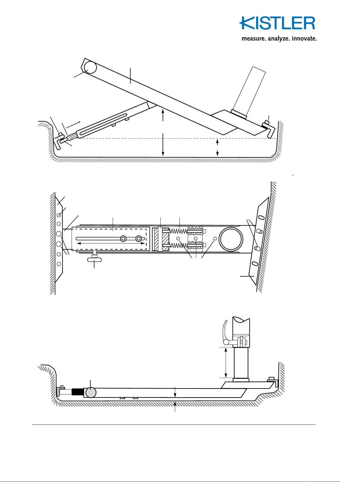
Fig. 1: Laptop car mounting, complete
telescopic tube
form guide rail
door sill
car floor
telescopic rail
knurled screw
allen screw 2 pcs M5x16
Base rail
form guide rail
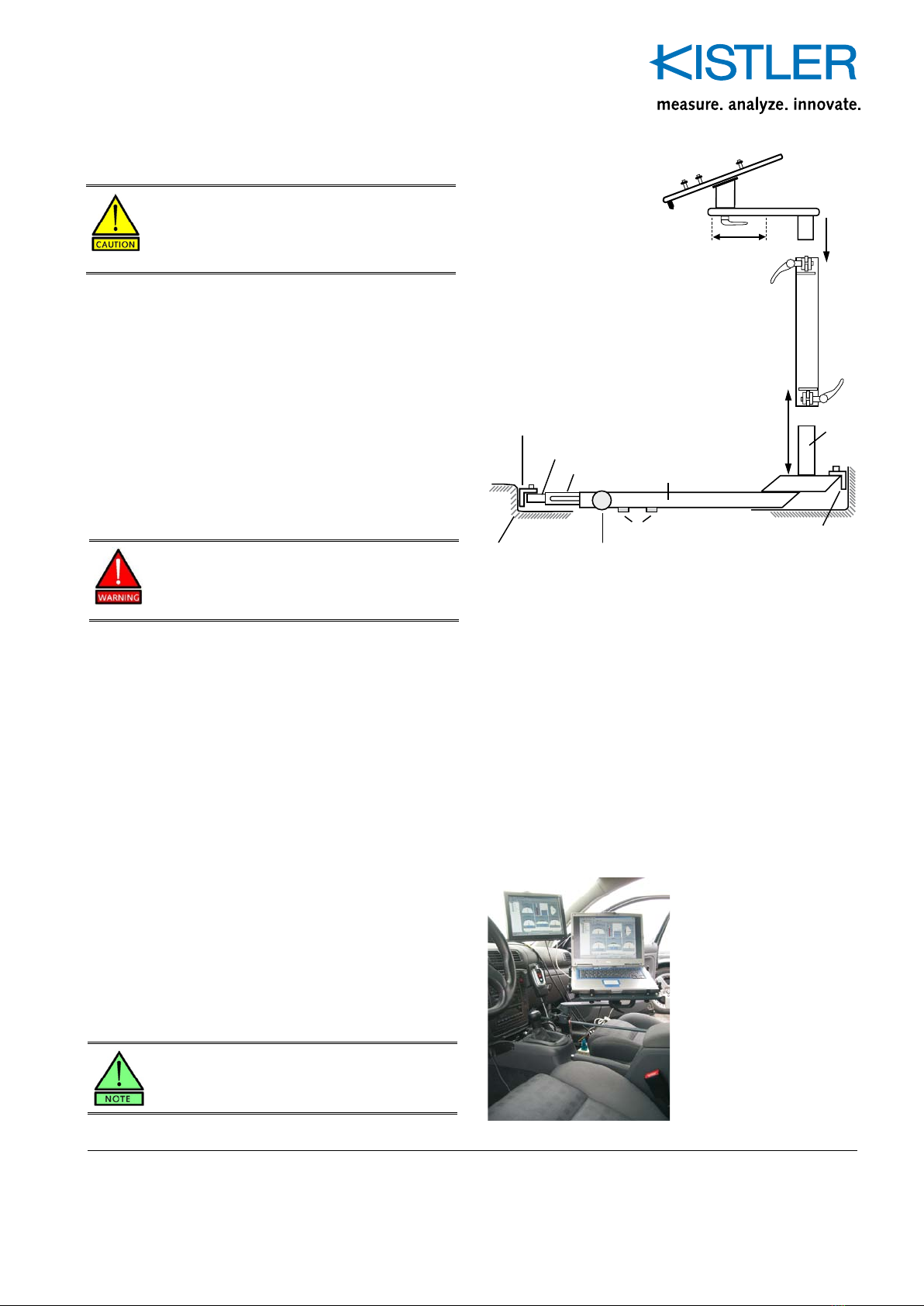
tunnel
reception
tube
locking lever
4. table top
adjusting slot 18 cm
3. swivelling
arm
360°
Q
10 cm
height adjustable
1. Base
2. Stand
Fig. 2: Mounted laptop car mounting
Mounting Instructions
First, adjust the base (1) to the footwell area of your vehicle.
For this purpose please loose both of the two allen screws
underneath the base rail and the lateral knurled screw. Then,
the telescopic rail will emerge from the base rail.
Put the base between tunnel and door sill. Be sure that the
reception tube is located at the tunnel and close to the front
edge of the co-driver's seat. Pull out the telescopic rail until
the bent joint (see fig. 3) is 10...15 cm above the vehicle
floor and both of the two form guide rails are 1...3 cm above
the floor and pressed against the tunnel and door sill. Slightly
tighten the two allen screws underneath the base rail and then
press the base towards the floor.
When reaching the limit point of the base rail, the insertion
movement of the telescopic rail should simultaneously stop.
The telescopic rail must definitely not reach its maximum in-
sertion depth before the base has reached its lowest point.
Otherwise, the springs that are intended to limit the pressure
forces may cease to work. In this case the enormous lever
forces that occur when pressing down the base could deform
parts of the body platform (tunnel).
In fixed condition, the base rail should be about 2 cm above
the vehicle floor. The form guide rail adapts to the bevel of the
tunnel.
If you have not got the ideal position with the first adjustment,
move the telescopic rail in the telescopic tube forward or
backward until you have reached the final position; then tigh-
ten the allen screws. You need to do this adjustment only once
per vehicle type. Now, tighten the lateral knurled screw. When
you want to remove the base you just have to loosen this
screw; then you can lift the mount.
Finally, you must tighten the screws of the form guide rail.
Before you start with the installation, please make
sure that no electric or other sensitive wires are un-
der the carpeting where the base is pressed against
tunnel and door sill of the vehicle.
Now, insert the stand (2) into the reception tube of the base.
Height adjustment of about 10 cm is possible. Make sure that
the base is mounted firmly by shaking the stand a bit. With
application of retained force, base and stand may move elasti-
cally but it must not be possible to lever the base out.
Connect the table top (4) with the swivelling arm (3); push and
swivel simultaneously. Be aware, you will need a certain effort!
Then insert the mounted table top/swivelling arm into the
stand, put this over the reception tube an secure it by exer-
ting the locking levers. Now the device is ready to mount the
laptop; use the accessories described on page 4.
Please also note the detail drawings on page 3.
Risk of injury!
Do not clasp the base rail with your fingers when
pressing it down but use your flat hand.
locking
lever