Kitagawa MR Series User manual

Original instructions
NC Rotary Table
INSTRUCTION MANUAL
Model:MR200RAE18
MA0580EHG
・This instruction manual is for production engineers and maintenance
personnel in charge of operation of this product. When a beginner uses
this product, receive instructions from experienced personnel, the
distributor or our company.
・Before installing, operating or maintaining this equipment, carefully
read this manual and the safety labels attached to the equipment.
Failure to follow these instructions and safety precautions could result
in serious injury, death, or property damage.
・Store this manual near equipment for future reference.
・If any questions related to safety arise about this manual, please
confirm them with the distributor or our company.
DANGER
Model: MRM200R40
Model: MRM200R40

NOTICE
Thank you for choosing the Kitagawa NC Rotary Table.
Kitagawa,a world-renowned precision equipment manufacturer, has developed the finest
quality NC Rotary Table with emphasis in high precision and rigidity as its basic principals
in design.
This unit is installed on the machining centers and suitable for indexing the angle of
machining position of the workpieces. Please contact us if it is used for any other
applications.
This NC Rotary Table has been designed to provide years of high precision performance.
To ensure optimum and trouble-free performance, please read this operation manual
carefully before using the unit and retain this copy for your future reference.
Please pay close attention to the procedures with the following warning marks to avoid
severe injury and/or accident.
Safety Alert Symbol
This is the industry “ Safety Alert Symbol ”. This symbol is used to call your attention to
items or operations that could be dangerous to you or other persons using this equipment.
Please read these massages and follow these instructions carefully. It is essential that you
read the instructions and safety regulations before you attempt to assemble or use this
unit.
Indicates an Imminently hazardous situation which,
If not avoided, will result in death or serious injury.
Indicates a potentially hazardous situation which, if
not avoided, could result in death or serious injury.
Indicates a potentially hazardous situation which, if
not avoided, may result in minor or moderate injury.
Instructions for table performance and avoiding
errors or mistakes.
DANGER
WARNING
CAUTION

EC DECLARATION OF CONFORMITY
We hereby declare that the following our product conforms with the essential health and
safety requirements of EC Directives.
Product : NC ROTARY TABLE
Type : MR Series, MRT Series ,GT Series, MX Series,
TMX Series, THX Series, TRX Series, TLX Series,
TBX Series, TUX Series, TR Series, TL Series,
TP Series, LR Series TM Series, TH Series,
TT Series, TW Series, DM Series
Directives : Machinery Directive 2006/42/EC
EMC Directive 2004/108/EC
The above product has been evaluated for conformity with above directives using the
following European standards.
Machinery Directive:
EN ISO 12100-1:2003+A1:2009, EN ISO 12100-2:2003+A1:2009,
EN ISO 14121-1:2007, EN 60204-1: 2006+A1:2009, others
EMC Directive:
Emissoion : EN 55011+A2:2007
Immunity : EN 61000-6-2:2005

CONTENTS
Page
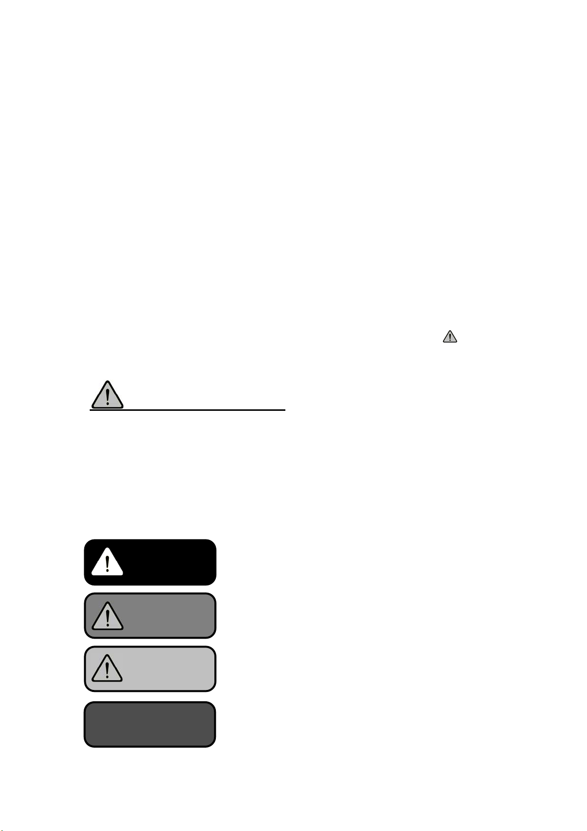
1. For Your Safety ・・・・・・・・・・・・・・・・・・・・・・・・・・・・・・・・・・・・・・・・・・・・・・・・・・・・・・・・ 1
2. Specifications ・・・・・・・・・・・・・・・・・・・・・・・・・・・・・・・・・・・・・・・・・・・・・・・・・・・・・・・・・・ 8
3. Accuracies ・・・・・・・・・・・・・・・・・・・・・・・・・・・・・・・・・・・・・・・・・・・・・・・・・・・・・・・・・・・・・ 10
4. Preparation ・・・・・・・・・・・・・・・・・・・・・・・・・・・・・・・・・・・・・・・・・・・・・・・・・・・・・・・・・・・・ 11
4-1. Installation
4-2. Lubrication
4-3. Required Oil Quantity
4-4. Recommended Lubricating Oil
4-5. Safety of Oil and Antirust Oil Used for the Unit
5. Inspection ・・・・・・・・・・・・・・・・・・・・・・・・・・・・・・・・・・・・・・・・・・・・・・・・・・・・・・・・・・・・・・ 14
6. Use of NC Rotary Table ・・・・・・・・・・・・・・・・・・・・・・・・・・・・・・・・・・・・・・・・・・・・・・・・ 14
7. Table Clamp and Unclamp ・・・・・・・・・・・・・・・・・・・・・・・・・・・・・・・・・・・・・・・・・・・・・・・ 15
7-1. General Instruction
7-2. Inlet Pressure for Table Clamp
7-3. Air purge
7-4. Confirmation of Clamp and Unclamp
7-5. Solenoid Valve for Clamp and Unclamp
8. Mounting the Workpiece ・・・・・・・・・・・・・・・・・・・・・・・・・・・・・・・・・・・・・・・・・・・・・・・・ 18
9. Maintenance Work ・・・・・・・・・・・・・・・・・・・・・・・・・・・・・・・・・・・・・・・・・・・・・・・・・・・・・ 19
9-1. Corrective Action in Case of Failure, and Disassembly
9-2. Before Performing Maintenance Work
10. Adjustment of Backlash between Worm Wheel and Worm Gear ・・・・・・・・・・ 20
10-1. Measuring the Backlash of the Worm Gear
10-2. Adjusting the Backlash of the Worm Gear
11. ZRN device ・・・・・・・・・・・・・・・・・・・・・・・・・・・・・・・・・・・・・・・・・・・・・・・・・・・・・・・・・・・・・ 25
11-1. ZRN device on table
11-2. ZRN device Adjustment
11-3. Sensor Mechanism
12. Motor Cover ・・・・・・・・・・・・・・・・・・・・・・・・・・・・・・・・・・・・・・・・・・・・・・・・・・・・・・・・・・・・ 27
12-1. Dismount
12-2. Waterproofing
13. Troubleshooting ・・・・・・・・・・・・・・・・・・・・・・・・・・・・・・・・・・・・・・・・・・・・・・・・・・・・・・・・ 29
14. Parts List ・・・・・・・・・・・・・・・・・・・・・・・・・・・・・・・・・・・・・・・・・・・・・・・・・・・・・・・・・・・・・・・ 32
15. Storage ・・・・・・・・・・・・・・・・・・・・・・・・・・・・・・・・・・・・・・・・・・・・・・・・・・・・・・・・・・・・・・・・・ 38

Page
16. Disposal of NC Rotary Table ・・・・・・・・・・・・・・・・・・・・・・・・・・・・・・・・・・・・・・・・・・・・ 38
17. Indexing Accuracy and Pitch Error ・・・・・・・・・・・・・・・・・・・・・・・・・・・・・・・・・・・・・・ 39
18. Mounting Rotary Joint (Option) ・・・・・・・・・・・・・・・・・・・・・・・・・・・・・・・・・・・・・・・・・ 40
18-1. Alignment of discharge opening face
18-2. Pining to supply part
Appendixes
Appendix 1 Outside View
Appendix 2 Wiring Diagram
Appendix 3 Details of Nameplate

1
1. For Your Safety
Basic Safety Tips
Please read this manual and follow instructions carefully.
We cannot assume responsibility for damage or accidents caused by misuse of the NC
Rotary indexing tables, through non-compliance with the safety instructions.
Turn off the main power of the machine prior to maintenance, check, or repair of
the unit, Failure to do so may cause severe injury and/or accident.
ON
OFF
OFF
DANGER

2
Tighten the bolts securely when mounting the unit on the machine table.
Please refer to the chart below for the
recommended tightening torque of the bolts.
Hex. Bolt Size Torque N・m
M10 33.8
M12 58.9
M16 146.3
M20 294.3
Make sure the working area is clear of any foreign object and/or hand when the
unit is in operation to avoid any serious accident and/or injury.
Do not apply cutting force which exceeds the specification in this manual. Failure
to do so may cause severe injury and/or damage to the unit.
WARNING

3
Please consult your local distributor before attempting any modification of the
unit.
Maintain adequate clearance between the unit and any part of the machine.
Avoid bending the external cables and air tube of the unit.
NO!
WARNING

4
Use a support, steady rest, or tailstock for heavy or long workpieces to prevent
any injury and/or accident.
Workpiece
Steady Rest
Tailstock
WARNING

5
When transporting the unit, make sure to use eye bolts and a sufficient leash or
wire.
Mount or dismount the workpiece to or from the unit while the unit is clamped to
avoid damage to the internal mechanism and diminished indexing accuracy of
the unit.
Leash or Wire Eye bolt
PNEUMATIC
CAUTION

6
Avoid sudden impact to any part of the unit which may cause damage to the
internal mechanism.
Supply air through Air combination (Air filter, Mist separator, regulator) +Drain
catcher. (The air supply port is on the motor case.)
Apply air purge inside the motor case
and be sure to provide dry air.
Periodically drain the water in air filter. (It is recommended to use the auto drain type.)
Mist separator
Relief valve
(Don't supply air from the
relief valve.)
NO!
OUT
IN
A
ir filte
r
Drain
Regulator
Drain catcher(SMC)
CAUTION

7
NOTICE
Mount all covers attached with O-rings. (No damages on O-rings)
Replace lubricating oil every 6 months.
O-ring
O-ring

8
2. Specifications
NC Rotary Table is dividing unit for the workpiece, usually operating machines.
[Machining Center,(NC)milling machine, (NC)drilling machine, etc. ]
Specifications are as below.
MODEL
ITEM
MR(M)
120
MR(M)
160
MR(M)
200
MR(M)
250
MR(M)
320
MX(M)
160
1 Table Diameter mm φ128 φ165 φ202 φ250 φ320 φ165
2 Table Height in Horizontal mm 136 145 173 180 210 150
3 Center Height in Vertical mm 120 140 140 180 225 140
4 Center Hole Diameter mm φ50 φ50 φ65 φ100 φ130 φ50
5 Thru. Hole Diameter mm φ32 φ40 φ45 φ70 φ106 φ40
6 Guide Block Width mm 10h7 14h7 14h7 14h7 14h7 14h7
7 Clamping Torque
[Pneumatics 0.5MPa]N・m 150 310 350 600 1200 310
8 Allowable Workpiece Dia. mm φ128 φ165 φ200 φ250 φ320 φ165
(Horizontal) kg 120 160 200 250 350 809 Allowable Mass
of Workpiece (Vertical) kg 60 80 100 125 180 40
10 Allowable Work Inertia kg・m20.22 0.51 1.00 1.95 4.49 0.25
11 Total Reduction Ratio 1/60 1/72 1/90 1/90 1/120 1/40
12 Max. Rotation Speed
(M signal specification)
min-1 50 41.6 33.3 33.3 25
(16.6) 75
13 Mass of Rotary Table kg 33 41 61 85 135 43
14 Operating temperature range °C 5~40
15 Operating humidity range %30~95
16 Operating altitude range
(above sea level) m 1000 or lower
17 Storage temperature range °C -10~60
18 Environmental pollution degree Degree 3
19 Noise level dB 79
※The noise level is measured at a distance of 1m from the NC rotary table in front, rear,
left, and right four positions of the unit.
※When storing the unit, conduct the antirust treatment and store it in a place free from
wetting, condensation, or freeze.

9
NOTICE
NOTICE
The above-mentioned list shows the value in standard
specification. Please refer to the outside view for details.
Table clamping torque is measured at 0.5MPa pneumatic
pressure. Max. Rotation Speed is at 3000 min-1(rpm) of the
motor rotation.
(In the case of MRM320: 2000 min-1(rpm))
Be sure to observe the allowance work inertia even if the
mass of workpiece is within the allowable value.
There is any case that the tailstock is required by the mass
of workpiece, shape, cutting conditions, etc.
For the conditions for using the table, refer to the above
specification columns and caution items. Set each cutting
condition so as not to exceed the allowance value.
CAUTION
CAUTION
CAUTION

10
3. Accuracies
Guaranteed Accuracies (Unit:mm)
Description of Inspection Guaranteed Accuracy
1 Run-out of center hole 0.01
2 Run-out of table surface 0.02
3 Parallelism of table surface and reference
plane for horizontal installation Per 150mm 0.02
4 Parallelism of rotating axis center line and
reference plane for vertical installation Per 150mm 0.02
5 Parallelism of rotating axis center line and
guide block center Per 150mm 0.02
6 Indexing accuracy Cumulative 20 sec [MX(M):40 sec]
7 Repeatability Cumulative 4 sec [MX(M):8 sec]
1
2
3
4
5
6,7 Index accuracy is measured with the optical device.

11
4. Preparation
Unpack the unit and remove the packing material.
4-1. Installation
1) When transporting the unit, hook ropes to the eyebolts attached and transport the unit
carefully, not giving a shock. The ropes used should be wire ropes having enough
strength to lift up the unit.
2) Clean the unit thoroughly with an adequate clean agent. When installing the unit on the
machine table, make sure there is no foreign material nor damage such as nicks and
burrs on the mating faces. Use an oil stone for correction if necessary.
3) The motor case may be removed depending on the maintenance work. Accordingly,
whenever possible, install the NC rotary table in a position where the motor case can
be removed. In case of vertical installation, the guide blocks will fit into the slotted
groove on the machine. If there is any play between the guide block and the T-slot,
place the unit against one side of the T-slot to eliminate the gap.
4) Firmly clamp down the unit to the machine with the furnished clamping fixtures.
Do not enter a part of your body under the NC rotary table
during transportation.
Unexpected accidents such as a disengagement of lifting
devices may cause the NC rotary table to drop on your
body.
Apply the clamping fixtures to the step of the unit provided,
and clamp the bolts with the specified torque.
The transport and lifting devices must be operated only by
the qualified persons for respective devices.
Operating the transport devices by an unqualified person
causes the NC rotary table or machine to be damaged due
to an operation error, resulting in accidents.
When transporting a pallet on which NC rotary table is
mounted, take measures against over-turning or drop.
Transporting the pallet with NC rotary table mounted
DANGER
WARNING
CAUTION
CAUTION

12
unstably may cause the NC rotary table to overturn and
then to drop from the pallet.
Disconnect electric cables and working fluid piping when
relocating the NC rotary table.
Relocating the NC rotary table with electric cables and
working fluid piping connected and hung down causes the
NC rotary table to be unstable or the worker to be tripped,
resulting in unexpected accidents.
Electric cables or working fluid piping may be damaged
during relocation, and if the NC rotary table is installed on
the machine again, unexpected accidents may occur.
If electric cables and working fluid piping cannot be
disconnected, secure them to the NC rotary table.
When the unit is installed on the machine, ensure to avoid
any interferences with any part of the machine. Especially
when the machine has a capability of X-Y-Z axis movement
of the spindle head or the machine bed, the interference
must be checked carefully before starting the operation.
4-2. Lubrication
Change the lubricating oil every 6 months. Be sure to drain
all oil from the unit first. When pouring oil into the unit,
make sure to clean the area around the lubrication port so
that no foreign material will enter the system. It may cause
severe damage to the internal mechanism. Use
recommended oil shown 4-4.
4-3. Required Oil Quantity
(Unit: liter)
MODEL
MR(M)
120
MR(M)
160
MR(M)
200
MR(M)
250
MR(M)
320
MX(M)
160
QTY.(l) at Horizontal installation 0.2 0.6 0.6 0.8 1.0 0.25
QTY.(l) at Vertical installation 0.2 0.4 0.4 0.6 1.0 0.25
Daphne Multiway 32MT (Idemitsu) is provided in the unit before shipping.
CAUTION
CAUTION
CAUTION

13
4-4. Recommended Lubricating Oil
・Grade of Viscosity : ISO VG32
4-5. Safety of Oil and Antirust Oil Used for the Unit
4-5-1. Scope of application
・ Specified lubricating oil
・ Specified hydraulic oil (MR ,MRT ,MX ,GT ,TM2100 ・3100 ,TH2100 ・3100 ,
TT(S)101・120,TT140,DM do not use)
・ Antirust oil applied to the unit at delivery (Houghton Japan, Rust Veto 377)
4-5-2. First-aid treatment
Aspiration: In case of much aspiration, go to a place where there is fresh air, and cover
your body with a blanket to keep your body warm. Consult a doctor if necessary.
Sticking to your skin: Wipe off the oil, and wash your skin with water and soap. If you feel
itchy or you get inflamed, consult a doctor immediately.
Entering your eye: Wash your eye with fresh water for at least 15 minutes, and then consult
a doctor.
Accidental drinking: Consult a doctor immediately without vomiting forcibly. If you are
polluted in your mouth, wash with water thoroughly.
・ For lubrication oils and hydraulic oils other than specified ones, and antirust oils
prepared by the customer, refer to the safety information prepared for respective
oils.
4-5-3. Flammable characteristics
・ Watch out for fire since lubricating oil and hydraulic oil are flammable. Hazardous
substances will be generated if they combusted.
・ The flash point of lubricating oil and hydraulic oil put in the unit at the delivery
exceeds 200°C. It may be different from that of the lubricating oil and hydraulic oil
prepared by the customer.
Maker Oil Name
IDEMITSU Daphne Multiway 32MT
MOBIL Vactra oil No.1
JX NIPPON OIL&ENERGY Uniway EV 32
SHELL Shell Tonna oil S32
COSMO Dynaway 32

14
・ Antirust oil is highly volatile and thus likely to catch fire, and also it mixes with air to
form explosive mixture gas.
・ The flash point of antirust oil applied to the unit at the delivery is 38°C. It may be
different from that of the antirust oil prepared by the customer.
4-5-4. Disposal of lubricating oil and hydraulic oil
Dispose of used lubricating oil and hydraulic oil exhausted from this unit in accordance with
the laws and regulations of your country. You may suffer punishment if you disposed of
waste oil without following the laws and regulations.
5. Inspection
Daily inspection
1) Confirm that the NC rotary tables (including jigs, if attached) are securely fixed.
2) Confirm that the chips accumulating in a rotary part of NC rotary table are removed.
3) Confirm that the electric connection cables and hoses are not damaged and the
pneumatic pressure is appropriate.
4) Confirm that the machine-zero operation and indexing operation and position.
5) Confirm that there is no abnormal vibration or noise. (eq. Body and motor)
6) Confirm that there is no abnormal heating. (eq. Body and motor)
Periodic inspection (Inspect the following items every six months.)
1) Confirm that muddiness of the lubricating oil.
2) Confirm that the connectors are securely attached and there is no damage on the
cables.
3) Confirm that corrosion and breaking of the wiring in the motor case.
6. Use of NC Rotary Table
This unit is installed on the machining centers, and on its table surface the chuck or fixture
is attached to clamp the workpiece. It indexes the angle of machining position by the
control of machining center or Kitagawa’s own controller. During the machining, the
working fluid is supplied to retain the workpiece.

15
7. Table Clamp and Unclamp
7-1. General Instruction
When the table is positioned, activate the table clamp,
When the table is in motion, inactivate the table clamp.
Improper procedures in table clamp and/or unclamp may
cause severe damage to the internal mechanism. This unit
is supplied with two pressure switches for table clamp and
unclamp for added safety.
Make sure that your cutting operation on the unit does not
exceed the table clamping force specified on the
specification sheet. This may cause damage to the internal
mechanism.
If some excessive pressures remain when it is unclamped,
the unit is operating under a half-clamp situation. This may
cause severe damage to the internal mechanism.
7-2. Inlet Pressure for Table Clamp
1) Use an appropriate filtration system. (Air Filter, Mist separator, Regulator, Drain catcher
set)
2) Connect the pipe exclusive for air pressure durable to max. operating pressure over 0.6
MPa to the air pressure supply port. The air pressure supply port is provided on the
motor case. See the external view attached for details.
3) Use this unit in the air pressure range of 0.45 to 0.6 MPa.
4) If the tail spindle is used, branch the air pressure from the NC rotary table to the tail
spindle by using a tail spindle connection port provided on the NC rotary table. See the
external view attached for the location of connection.
7-3. Air purge
According to the circumstance of use, the dew may be occurred in the motor case.
Air is exhausted from the portion of the air exhaust so that it causes the obstacle of electric
parts or each part.
WARNING
CAUTION
CAUTION
CAUTION
This manual suits for next models
19
Table of contents
Other Kitagawa Power Tools manuals