The right hand side of the circuit is in the same state that the left hand side
started in Stage 1, but with C2 charging instead of C1. When the charge gets
high enough the circuit flips back to Stage 1.
R3 is needed to limit the amount of current flowing through the LED. The
transistors aren’t turned fully on so also contribute to the limiting of current
flowing through the LED. This means the current limit resistor is smaller than
it would otherwise be.
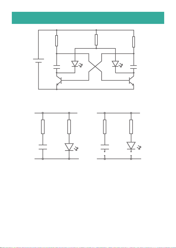
HOW THE BIKE LIGHT WORKS
Q2 is now turned on which connects
LED2 and C2 to 0V. This turns LED2
on. This connection of C2 to 0V causes
the voltage across it to drop below
0.7V turning off Q1. Now C2 starts to
charge through the resistor R2
causing the voltage across it to
increase. The voltage at the base of
Q1 starts to rise as C2 charges as
they are both connected to each other.
As C2 has less than 0.7V across it Q1
is turned off. This means LED1 is not
connected to 0V and is therefore
turned off. C1 (which has more than
0.7V across it) is gradually discharging
into the base of Q2.
State 2 (see picture above):
V+
R3
R2
C2
LED2
0V
V+
R3
R1
C1
LED1
0V