Kiwami 4D-970 User manual

Contents
1.
・・・
2.
・・・
3.
・・・
4.
・・・
5.
Easter egg list
・・・
6. Servicing operation guide
・・・
7. Exploded diagram
・・・
8. Parts price list
・・・
Service Manual
【Home use】Massage chair
Medical
device
Kiwami
4D-970(BK/Black)
Launching date
November, 2016
〇
4D-970
4D-970(CS/Beige)
4D-970(BR/Brown)
Category
A45
2
No.
1
Specification
Electric schematic diagram
Error number list
Malfunction diagnosis flowchart
Fuji Medical Instruments Mfg. Co., Ltd.
Parts in this manual are important parts for function, safety.
Make sure to use designated parts.
The parts with ★mark are especially important for safety.

1.General specification
2.Use conditins
2-1Environment of usage
a.Ambient temperature 5~35℃
b.Relative humidity 30~90%Rh
2-2Storage environment
a.Ambient temperature -20~60℃
b.Relative humidity 30~90%Rh
3.Operation speed and air pressure
Slowest Slow Mid High Tolerance
8 18 24 30 ±5
Slow,
Ex-mode
tapping
Slow Mid High
250±50
270~440±50 370~540±50 470~650±70
Highest
5.4±0.5
PTC heater(Back/Sole of feet)
Strength(cm/sec)
50Hz/60Hz
Highest
5.4±0.5
1.0±0.5
1.7±0.5
Knead(rpm)
Tapping(rpm)
Elevation(cm/sec)
Lowest
Lowest
Heater
3
less than 60℃
Product serial number
№PRM4S00000001~
2-pole DC motor、DC24V
Strength motor
Air pump form
Stacking limit
Reclining motor
DIAPHRAGM TYPE RECIPROCATING
Tapping motor
Elevation motor
2-pole DC motor、DC24V
Motor form
2-pole DC motor、DC24V
Footrest slide motor
2-pole DC motor、DC24V
800(W)×1,370~1,920(L)×1,230~810(H) mm
744(W)×1,618(L)×751(H)
PVC leather、Polyester tricot
Main unit dimension
102kg
130 W
40 W
Electric motor power supply
Electric heater power supply
88 kg
30分
90 W
Electric power supply
Power consumption
━
4D-970
Controlled medical device generic term:Home-use electric massager
Medical device approval number
Contents
Specification
Remark
Category
Model
Dimension
AC100~240V 50/60Hz
Mass
Name
Rating
Rated time
Net weight
Gross weight (in packing)
Packing dimension
0.75mm2×2 outside instruments/approx. 3.0m
Power cord
2-pole DC motor、DC24V
Material of cloth
Kneading motor
4D-970
Product specification

(rpm)
Reclining(up)
Reclining(down)
Slide(elongate)
Slide(contract)
Footrest(upper)
Footrest(lower)
Air pressure
4.Variety of functions
4-1Selection of course
Mechanic
【Basic functions】
①⑪21
②⑫22
③⑬23
④⑭24
⑤⑮25
⑥⑯26
⑦⑰27
⑧ ⑱
⑨ ⑲
⑩ ⑳
【Conbination of functions】
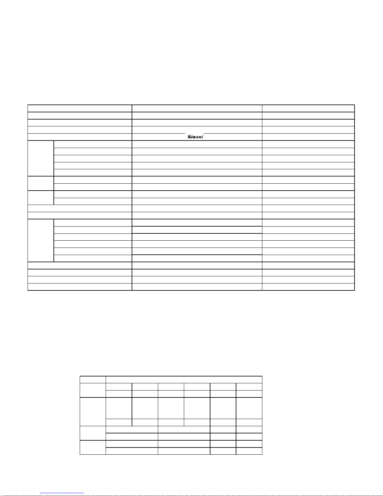
Whole/Part Speed Intensity Width Remarks Whole/Part Speed Intensity Width Remarks
Knead up Whole/Part/Point knead 12 levels ×Wave rolling Whole/Part knead 12 levels ×knead + rolling
Knead down Whole/Part/Point knead 12 levels ×Shoulder tapping Shoulder position ×12 levels ×Up/down
Tapping Whole/Part/Point tapping 12 levels 〇Push & knead Whole/Part/Point knead 12 levels ×
Wavelet Whole/Part/Point knead/tapping interlock 12 levels ×Shoulder blade line Preposition × × ×
Rolling Whole/Part ×12 levels 〇knead down + tapping Upper shoulder press Preposition × × ×
Stretch Whole/Part/Point ×12 levels 〇Shiatsu Whole/Part/Point ×12 levels 〇
Stretch knead up Whole/Part/Point knead 12 levels ×Stretch + knead up 3D knead up Whole/Part/Point × × ×
Stretch tapping Whole/Part/Point tapping 12 levels 〇Stretch + tapping 3D knead down Whole/Part/Point × × ×
Stretch wavelet Whole/Part/Point knead/tapping interlock 12 levels ×Stretch + knead down + tapping 3D tapping Whole/Part/Point × × 〇
Neck relax Shoulder position × × × Up/down 3D wavelet Whole/Part/Point × × ×
Extreme-knead Shoulder position × × × Up/down Relax knead up Point knead 12 levels ×
Extreme-tapping Shoulder position × × × Up/down Paraspinal Whole knead 12 levels ×
Waist ex.knead Shoulder position × × × Palmar knead up Whole/Part/Point knead 12 levels ×
Waist ex.tapping Shoulder position × × × Palmar knead down Whole/Part/Point knead 12 levels ×
Buttock Preposition × × × Waist shiatsu Waist position × × ×
Loop knead up Whole/Part/Point knead 9 levels +Extreme 3 levels ×Knead up + up/down
Loop knead down Whole/Part/Point knead 12 levels ×Knead down + up/down
Loop tapping Whole/Part/Point knead/tapping interlock 12 levels ×Loop knead up + tapping
Loop wavelet Whole/Part/Point knead/tapping interlock 12 levels ×Loop knead up + tapping
【Adjust function】
Air unit
【Selection of parts】
①・SHOULDER ⑥-
②・ARM ⑦-
③・WAIST・BUTTOCK ⑧-
RELAX KNEAD UP
19 ±3.0
3D
LOOP WAVELET
SHIATSU
NECK RELAX
0.045 Mpa
STRETCH
SHOULDER TAPPING
WAVE ROLLING
ROLLING(whole body)
ROLLING(part)
・Strength adjustment(12 levels)
EXTREME-KNEAD
RELAX KNEAD DOWN
EXTREME-TAPPING
LOOP KNEAD UP
5 ±1.0
50Hz
60Hz
17 ±3.0
5 ±1.0
KNEAD UP
KNEAD DOWN
TAPPING
17 ±3.0
50Hz
60Hz
18 ±3.0
LOOP TAPPING
LOOP KNEAD DOWN
WAVELET
PUSH & KNEAD
SHOULDER BLADE
UPPER SHOULDER PRESS
PARA SPINAL
PALMAR KNEAD UP
PALMAR KNEAD DOWN
WAIST SHIATSU
・Speed adjustment(3 levels)
・Partly adjustment(3 types)
・Width adjustment(3 levels)
・Height adjustment

④・Foot ⑨-
⑤-⑩-
【Adjust function】
【Mechanic・Air combination】
Arrange imultaneous motion by air function, selection of parts while mechanic operates.
4-2Auto course
VIP
Sommelier
Slow stretch
Air relaxation
Extreme rejuvenation
Rejuvenation
Refresh
Relax
Soft
Extreme whole body stretch
Whole body stretch
Whole body air
Extreme rejuvenation
Rejuvenation
Refresh
Relax
Extreme rejuvenation
・Waist Rejuvenation
Refresh
Relax
・Memory
・Adjust function Mechanic unit
・Shoulder position adjustment (up) (down)
・Shoulder position adjustment (up) (down) (forward) (backward)
・Waist position adjustment (up) (down)
・Strength adjustment (7 levels)
・Skip (skip the massage mode)
・Repeat (repeat the massage mode)
Air unit
・Double stretch (OFF/ON)
・Foot stretch (OFF/ON)
・Knee stretch (OFF/ON)
・Hold (OFF/ON)
・Pelvis (OFF/ON)
(Start/Stop)
(Emergency stop of the operation)
Lock function(Press STOP button for over 2 seconds)
(up) (down)
(Contraction) (Extension)
(up) (down)
Auto store of backrest and footrest.
・Strength adjustment(5 levels)
・Arm strength adjustment(3 levels)
・Stretch(OFF/Knee/Foot/Double)
・Indivisual movement(OFF/With foot/With waist/Twist)
・Twist
・30 min
・Whole body
・Stretch
・Neck/Shoulder
【ON/OFF】
【STOP】
・Air(OFF/Pulse/Hand knead)
・Shoulder strength (5 levels/OFF)
・Arm strength (3 levels/OFF)
【Child lock】
【Footrest angle】
【Footrest extension/Contraction】
【Reclining】
【Store】
・Waist・Seat strength (5 levels/OFF)
・Foot strength (5 levels/OFF)
・Pulse (OFF/ON)
・With foot (OFF/ON)
select
select
select
select
select

Main body
Remote controller


①
Waist
⑥
right buttock
⑪
Toe
②
Waist (Right)
⑦
left buttock
⑫
Calf rear
③
Waist (Left)
⑧
Thigh
⑬
Calf side
④
Arm (Front)
⑨
Waist side
⑭
⑤
Arm (Back)
⑩
Sole of feet
⑮
Air-discharge aperture No. and homology for each part of air bag.
Mechanic unit KX-7872
PCB unit KX-3982
Remote control unit KX-2982

7. Safety precaution
When an error occurs, turn off air massage, mechanic massage, reclining, footrest, footrest Expansion and contraction, air movement, heater.
Error mode could be released by turning the power off.
Details of error are discribed on chart 7-1
Error
No.
2
3
4
5
6
8
9
10
11
14
18
19
20
21
22
23
24
25
26
27
28
29
30
40
41
42
43
44
45
46
60
61
Remote control : It does not have communication processing for 1 second in a row.
Main circuit board : power outlet 24V become below 20V after 0.5 second pass from power on with 24V.
Main circuit board : power outlet 24V become below 12V for 0.1 second in a row.
Chart 7.1 : Error display
Chart 7-1 : Error contents
Main circuit board : CRC does not match for 1 second in a row.
Main circuit board : header does not match for 1 second in a row.
Main circuit board : remote control is in busy state for 1 second in a row.
Main circuit board : It does not receive a data from remote control for 1 second in a row.
Remote control : CRC does not match for 1 second in a row.
Remote control : header does not match for 1 second in a row.
In case footrest limit signal is not entered for more than 30 seconds during footrest down operation.
Actuator connector comes off, continuous detection for 0.5 second.
In case footrest expansion and contraction pulse is not entered for more than 2 seconds during footrest expansion and contraction operation.
In case limit signal is not entered for more than 15 seconds during footrest expansion operation.
In case limit signal is not entered for more than 15 seconds during footrest contraction operation.
Continuous detection of the overcurrent for footrest expansion and contraction motor for more than 0.3 second during footrest expansion and contraction operation.
Tapping motor lock signal is continuously on for 2 seconds.
In case reclining pulse is not entered for more than 2 seconds during reclining operation.
In case footrest pulse is not entered for more than 2 seconds during footrest operation.
In case reclining limit signal is not entered for more than 30 seconds during reclining up operation.
In case reclining limit signal is not entered for more than 30 seconds during reclining down operation.
In case footrest limit signal is not entered for more than 30 seconds during footrest up operation.
Connector comes off, continuous detection for 0.5 second.
Error contents
Limit sensor signal is not on for more than 42 seconds during moving up.
Lower limit stop sensor signal is not on for more than 42 seconds during moving down.
In case elevation pulse is not entered for more than 3 seconds during elevating operation.
Malfunction of weak position sensor(weak signal is not off for more than 6 seconds during moving to "strong" direction)
Malfunction of weak position sensor(weak signal is not on for more than 6 seconds during moving to "weak"direction)
In case Strong/Weak pulse is not entered for more than 1 second during strength operation.
In case 「Wide」position pulse is not entered for more than 25 seconds during kneading operation.
In case Knead pulse is not entered for more than 2 seconds during kneading operation.
Equipment error(from the main board)
Equipment error(from remote control)

0.Trouble shooting(4D-970))
■Precautions for repair or exchange
a. Make sure to unplug when you exchange parts, teardown, inserting or removing the connector.
b. Make sure to work for repair after following actions when you touch main circuit board(each board) as
semiconductor(Ex. IC) is static-sensitive.
※Remove human earth or touch an earth(Ex. refrigerator, washing machine) directory by hand and release the static from
electrically charged body.
c. Do not touch power supply board without discretion as high(AC100V~240V) and low(24V・12V・5V) pressure
are mixed in the power supply board. It may cause electric shocks. Please be very careful with checking voltage.
1.Power does not turn ON
(4D-970:LCD does not light up)
Is the power cord plug connected?
Isthemainpowerswitchon?
Connect the power cord plug with the receptacle.
No
Yes
Switch ON
Did you press “ON/OFF “button?
Press “ON/OFF “ button.
Check if each cord in the main circuit
board is connected to appropriate
connector.
Power cord・Main circuit board(CN1)
Remote cord・Main circuit boardCN4)
8 pin cord・
Power supply board(CN301),
Main circuit board(CN1)
2 pin cord・
Power supply board(CN601)
Main circuit board(CN2)
Make sure to connect each cord.
Power mark overvoltage is appeared on
power supply board connector of power
cord(CN1)?
Check with the tester.
Breaking or cut of power cord or
disconnection of power switch.
Repair to exchange.
No cut or breaking of remote cord?
Exchange remote control.
Exchange remote cord.
Yes
Yes
Yes
Yes
Yes
No
No
No
No
No
Below voltage is shown from the
connector of power supply board
(CN301)? Check with the tester.
Between Pin # 1 - #2:DC12V
Exchange the power supply board.
No
Yes
Remote cord is firmly connected to remote
board connector(CN1)
電源コード・電源基板(CN1)
リモコンコード・制御基板(CN4)
8芯コード・
電源基板(CN301) 制御基板(CN1)
2芯コード・
電源基板(CN601) 制御基板(CN2)
Make sure to connect it.
Yes
No
Below voltage is shown from the
connector of main circuit board(CN4)?
Check with the tester.
Between Pin# 1 - #2:DC5V
Exchange main circuit board.
No
Yes

2.Malfunction (LCD is lighted up)
(4D-970):LCD is lighted up)
Error is shown?
4D-970:
Is “Error・Switch ON again” displayed
on LCD?
Check service # (Error #) and each
part.
3.In case service #(Error #) is
displayed.<Refference>
Yes
2.1
Tapping does not work.
<Reference>
Air function does not work.
All parts do not work.
No
Disconnection of
hose?
Yes
No
Connect the hose.
Yes
Bended hose?
(Check each hose)
Correct the bended part.
Teared airbag?
Exchange the airbag.
Yes
2.2
Air function does not work.
<Reference>
Yes
Yes
No
No
2.3
Extension and contraction of
footrest does not work.
2.4
Heater does not work.
Settable or operable by each remote
button?
Does remote panel work when you press
LCD touch panel?
Exchange remote control.
No
No

2.1 Tapping does not work.
Yes
Is tapping motor connector of main circuit board (CN14) firmly
connected?
No
Connect the connector firmly.
Is the voltage out on the connector of main circuit board(CN14)
when tapping mode is set with the remote?
(The voltage is changed by operation mode)
Yes
No
Replace the main circuit board.
No
Is there any backlash on knead balls?
(Is there any break on driving part of knead ball unit?)
Yes
Is 9 pin connector of tapping motor firmly connected?
No
Connect the connector firmly.
Yes
Is 2 pin connector of tapping motor firmly connected?
No
Connect the connector firmly.
Is there any cut on 9 pin cord of mechanic or 9 pin cord of control
unit?
Exchange the cord.
No
リモコンのコントロール基板、ま
たはゴムボタン交換
Yes
No
Is there any disconnection, cut or wear of tapping belt?
Reattach or replace the tapping belt.
Yes
Exchange the tapping motor.
No
Exchange the knead ball unit.
Yes

2.2 Air function does not work.
Pump is working.
Insert the connector firmly.
Malfunction of main circuit board.
Replace the main circuit board.
Is the voltage out on the connector of main
circuit board CN10 (for pump power
supply)?
(Voltage is changed by operation mode.)
Replace the pump.
Is the lead wire of pump firmly inserted into
the connector of main circuit board(CN10)?
Replace the relay board.
No
Yes
Yes
No
Yes
No
Exchange the 6P cord for relay
board.
Insert the connector firmly.
Is the 6Pcord for relay board cut?
Is the 6P cord firmly inserted into the connector of relay board CN6 and the
connector of main circuit board CN23、CN22、CN3?
Check if the connecting position is correct.
(CN3 is not used for Premium 4.0)
Is the lead wire of each electromagnetic valve unit firmly inserted into the
connector of relay board CN1-5?
Yes
No
No
Yes
Yes
Replace the main circuit board.
Is DC12V(approx..) out between GN pin #1 and #2-6 of the connector of main
circuit board(Connector for the relay board CN23, CN22, CN3)? (Check with the
tester)
No
Yes
Replace the electromagnetic
valve unit after checking
ventilation flue.
No
Is each electromagnetic valve working?
Yes
Replace the electromagnetic
valve unit.
Is the plunger of each electromagnetic valve unit working?
Check if the moving sound could be heard.
Yes
No
No
Replace the electromagnetic
valve unit.
Is DC12V(approx..) out on the connector of relay board CN1~5?
(Check with the tester when each part is operated.)
Yes
No

2.3 Extension and contraction of footrest do not move.
2.4 Heater does not work.(It does not heat up)
Is the footrest movable to maximum upper angle?
No
Is DC24V(approx..) out on the connector of main circuit
board(CN18, 19) when heater is ON.
(Check with tester.)
No
Replace the main circuit board.
Yes
Exchange heater or the cord for heater.
Is there any disconnection for each connecting part of
heater?
No
Connect the connector firmly.
Yes
Is any error occurred?
4D-970:
“Error occurs・Switch the power again” is displayed on the LCD.
Check each part after confirming service No.(Error no.)
3.In case service No.(Error No.) is displayed. <Reference>
Yes

3.When an error occurs.
4D-970:Service no.(Error no.) is displayed on the LCD of remote.
Error
No.
2
3
4
5
6
8
9
10
11
14
18
19
20
21
22
23
24
25
26
27
28
29
30
40
41
42
43
44
45
46
60
61
Remote control:It does not have communication processing for 1 second in a row.
Main circuit board : power outlet 24V become below 20V after 0.5 second pass from power on with 24V.
Main circuit board : power outlet 24V become below 12V for 0.1 second in a row.
Main circuit board : CRC does not match for 1 second in a row.
Main circuit board : header does not match for 1 second in a row.
Main circuit board : remote controlis in busy state for 1 second in a row.
Main circuit board : It does not receive a data from remote controlfor 1 second in a row.
Remote control:CRC does not match for 1 second in a row.
Remote control:header does not match for 1 second in a row.
In case footrest limit signalis not entered for more than 30 seconds during footrest down operation.
Actuator connector comes off, continuous detection for 0.5 second.
In case footrest expansion and contraction pulse is not entered for more than 2 seconds during footrest expansion and contraction operation.
In case limit signal is not entered for more than 15 seconds during footrest expansion operation.
In case limit signal is not entered for more than 15 seconds during footrest contraction operation.
Continuous detection of the overcurrent for footrest expansion and contraction motor for more than 0.3 second during footrest expansion and contraction operation.
Tapping motor lock signal is continuously on for 2 seconds.
In case reclining pulse is not entered for more than 2 seconds during reclining operation.
In case footrest pulse is not entered for more than 2 seconds during footrest operation.
In case reclining limit signal is not entered for more than 30 seconds during reclining up operation.
In case reclining limit signal is not entered for more than 30 seconds during reclining down operation.
In case footrest limit signalis not entered for more than 30 seconds during footrest up operation.
Connector comes off, continuous detection for 0.5 second.
Error contents
Limit sensor signal is not on for more than 42 seconds during moving up.
Lower limit stop sensor signal is not on for more than 42 seconds during moving down.
In case elevation pulse is not entered for more than 3 seconds during elevating operation.
Malfunction of weak position sensor(weak signal is not off for more than 6 seconds during moving to "strong"direction)
Malfunction of weak position sensor(weak signal is not on for more than 6 seconds during moving to "weak" direction)
In case Strong/Weak pulse is not entered for more than 1 second during strength operation.
In case 「Wide」position pulse is not entered for more than 25 seconds during kneading operation.
In case Knead pulse is not entered for more than 2 seconds during kneading operation.
Equipment error(from the main board)
Equipment error(from remote control)
3.1
Service no.「02」
Service no.「03」
Service no.「04」
Is the back frame normal?
Is there any deformation of gear and elevation gear of the back
frame? Or is the engagement of gear normal?
Check if the amount of grease is normal.
(Check the engagement of gear and movement.)
Add grease when they are not enough.
Replace “UD shaft assy” and “guide
roller J assy” when the gear has
deformation. Remove the mechanic part
from the back frame and replace it
correctly when the engagement of the
gear is abnormal.
No

3.2
「02」「 03」
「04」
Yes
Is there any malfunction on the PCB?
Does error occur after replacing a PCB?
Yes
No
Exchange the PCB.
Replace UD shaft (assy) for mechanic.
(Check if there is abnormal sound.)
Does the elevation motor
work normally?
Yes
Connect the connector firmly.
No
Is each connector connected firmly?
Check the mechanic 9 pin cord, the
connector for elevation motor, relay
connector of 9 pin cord, the
connector(CN15) for elevation motor
for main circuit board.
Yes
No
Are 9 pin cord for mechanic or control unit cut?
Is there any defect on main circuit board?
Does error occur after replacing the main
circuit board?
Yes
Is there any clogging in the elevation sensor board (relay board
base) or elevation sensor?
Yes
Service no.「05」
Service no.「06」
Service no.「08」
Replace the elevation motor.
Yes
No
Replace the main circuit
board.
「05」「 06」
「08」
Does strength motor works
normally?
Yes
Connect the connector firmly.
No
Is each connector connected firmly?
Check the connector of 9 pin cord of
mechanic part for strength motor,
relay connector of 9 pin cord of
control, connector(CN16) for strength
motor of main circuit board.
Yes
Yes
Are 9 pin cord of mechanic part or main circuit
board cut?
Exchange the cord.
Yes
Is there any malfunction on main circuit
board? Does error occur after exchanging the
main circuit board?
No
Exchange the strength motor.
Yes
No
Replace the main
circuit board.

3.3
Service No.「09」
Service No.「10」
Is there any defect on relay board?
After exchange of relay board, is there any error occur?
No
Exchange relay board.
Yes
Is there any damage on gear of Mechanic (HL shaft assy ) ?
Is stronger and weaker (HL) sensor cord of junction basement Unit
inserted surely in connector ? Or is there any beak of cord ?
Yes
Insert surely connector
Or exchange HL sensor assy
Is there any break of cord for mechanic 11 sensor core cord, or
control unit 11 sensor core cord ?
Is there any come off from each connector ?(basement board unit ,
junction unit)
Yes
No
Exchange cord.
Or insert connector surely
Yes
Is there any defect on stronger and weaker (HL) sensor basement
board ?
After exchange of HL sensor basement board, is there any error
occur?
No
Exchange HL sensor assy.
「09」
「10」
Is there any break of any knead sensor board ?
Yes
No
Exchange knead ball unit
Do knead motor work
normally ?
Yes
Connect connector surely
No
Is each connector surely connected ?
Confirm connector for Knead motor
of Mechanic 9 center core cord,
junction connector of control 9 center
core cord, or connector (CN17) for
knead motor of control basement
unit.
Yes
No
Is there any break for Mechanic 9 sensor core
cord or control unit 9 sensor core cord ?
Exchange cord
Yes
Is there any defect on main circuit board ?
After exchange of main circuit board, is there
any error occur ?
No
Is there any clogging etc. of knead sensor board or knead sensor?
Yes
No
Remove clogging
Exchange stronger and weaker motor
Yes
No
Exchange the
main circuit
board.
Is knead sensor cord surely inserted connector of junction
basement board ?Or is there any break of cord ?
Yes
No
Insert connector surely Or
Exchange knead sensor cord
Is there any break or change of shape inside gear case ?
Yes
No
Exchange knead ball unit
Exchange control board unit
No
Exchange HL shaft assy
Yes

3.4
3.5
Types of connecting equipment of control unit and remote
control unit are different.
Connect correct remote controller or control unit.
Service No.「11」
Service No.「14」
Exchange main circuit board.
Is there any break for Mechanic 11 sensor core code or control unit
11 center core cord ?
Is there any come off for each connector ?(basement board、juncion
board)
Is there any defect of knead sensor basement ?
After exchange knead sensor basement board, is there any error
occurred ?
Exchange knead sensor basement
unit
No
Is 11P cord for control side Mechanic inserted surely connector
(CN8) ?
No
Connect connector surely
Service No.「18」
Yes
Is junction connector of Mechanic 11P cord surely inserted ?
No
Connect connector surely
Yes
Yes
Is Mechanic side 11P code surely connected to connector (CN3)
of junction basement board ?
No
Connect connector surely
Yes
Is HL sensor cord surely connected to connector of junction
basement board (CN2) ?
Is HL sensor cord surely connected to connector of HL sensor
basement board (CN1) ?
No
Connect connector surely
No
Exchange cord. Or
Insert connector surely
Does error occur after replacing knead ball unit?
Yes
Yes
No
Exchange the knead ball unit.
Yes
Is any malfunction on relay board?
Does error occur after replacing the relay board?
Yes
No
Exchange the relay board.

3.6
3.7
3.8
3.9
No
When taking off tapping belt,
twist pulley of knead ball unit,
twist easily?
Exchange knead ball unit
Service no.「19」
Yes
Exchange tapping motor
No
Does something get stuck under
Backrest ?
Remove something under
backrest
Service No.「20」
Yes
Exchange reclining actuator
Service No.「22、23」
No
Is 2-pin core cord, 4-pin core cord
of reclining actuator surely
inserted to connector of control
basement board (CN12, CN6)?
Insert connector surely
Yes
Service No.「21」
Yes
Exchange Ottoman actuator
No
2 center core code, 4 center core
code of Ottoman actuator is surely
inserted to connector of control
basement board(CN12,CN5).
Insert connector surely
No
Is 4 center core code of reclining
actuator surely inserted to
connector of control basement
board (CN6).
Insert connector surely
Exchange main circuit board.
Yes
Is there any break of Mechanic side 11P cord, control side 11P
code ?
No
Exchange applocable cord。
Is there any break of HL sensor cord ?
No
Yes
Exchange HL sensor cord

3.10
3.11
3.12
Exchange reclining actuator
Service No.「24、25」
Exchange footrest actuator
Is footrest reclining signal line and footrest reclining driving
signal line inserted surely to the connector (CN6、CN5、CN7)?
No
Connect connector surely.
Service No.「26」
Is there any broken line in the footrest moving unit signal line
(4 center core) ?
(Confirm by exchanging tester or stretching sensor unit of
confirming items(non-defective products)
No
Exchange sensor unit for footrest moving
units.
Exchange main circuit board.
Yes
Yes
Service No.「27」
Yes
No
Is 4-pin core code of footrest
actuator inserted surely to the
connector (CN5) of control
basement board ?
Insert connector surely
Yes
Is the junction connector for footrest driving connected surely?
No
Connect connector surely
Yes
Is Ottoman driving 6-pin code for connection of control unit
broken ?
No
Yes
Exchange footrest driving 6-pin code.
Is footrest or reclining signal line broken ?
After exchange alternate actuator, is there any other error
occurred ?
No
Exchange applicable actuator.
Junction connector of motor 2 pin code and stretching sensor
signal 6 pin code for footrest moving unit is surely connected ?
No
Connect surely junction connector
Is Connector of each code for Ottoman moving unit surely
connected 6 pin connector (CN7) for sensor signal of control
basement board, and Motor 2 pin connector (CN13) ?
No
Connect surely connector
Yes
Yes
Yes

3.13
3.14
3.15
Service No.「28、29」
Exchange footrest moving Unit
Repair footrest frame when there is defect in footrest frame.
Is there any break line of control basement side 6 pin code for
footrest moving sensor signal, and 2P code for stretch
motor ?
Exchange applicable cord on main circuit
board.
Service No.「60 」
Service No.「61 」
Is each code surely connected to connector
of each basement board ?
8 center core code・
Electric power supply basement board
(CN301), Control basement board(CN1)
2 center core code・
Electric power supply basement board
(CN601), Control basement board(CN2)
Is there break line of 8 center core
code, 2 center core code of Electric
powe supply basement connection ?
Insert surely
No
Yes
Exchange code.
No
Yes
No
Is Connector of remote controller 6
center core code is surely
connected to control basement
board (CN4), remote control
basement board (CN1) ?
Connect connector surely
Service No.「40 」
Service No.「41 」
Service No.「42 」
Service No.「43 」
Service No.「44 」
Service No.「45 」
Service No.「46 」
No
Yes
Is About DC24V on the connector(CN13) of main circuit board
confirmed when press [extension] or [Contraction] on remote
controller?
Any malfunction on sensor board of footrest driving unit or any
cut or break on 4-pin cord for sensor signal?
Exchange footrest extension/contraction driving unit.
Yes
No
No
Exchange main circuit board.
Yes
Exchange sensor unit(with harness).
Table of contents