Kiyo D ULTIMATE Operating manual

User and installation manual
r e v. : 1 7 1 0 2 4


1
KIYO D ULTIMATE
Complete Speed Capture Defense System
COMPLETE SPEED CAPTURE DEFENSE SYSTEM – ALL IN ONE PACKAGE
The KIYO D Ultimate system ensures safe driving conditions by detecting all types of
speed enforcement cameras that may occur in trac. With the help of its radar antenna,
laser sensors and updatable GPS database, it warns the driver to xed- and mobile
cameras, LIDAR speedcams, average speed cameras and to many other dangers.
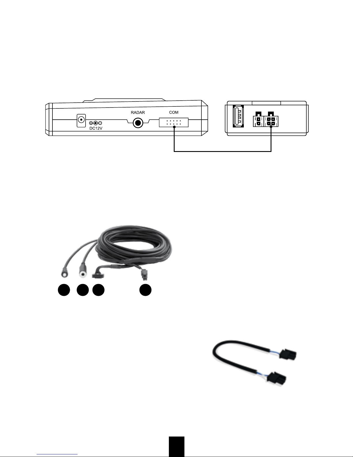
The system is made up of dierent modules that can be bought separately and some
of these can function on their own. To achieve full protection against speed cameras,
the installation of the complete system is needed, which includes a GPS U1 xed
camera detector, a RAD U1 radar detector, an Ultimate laser unit and all the necessary
accessories to connect these modules.
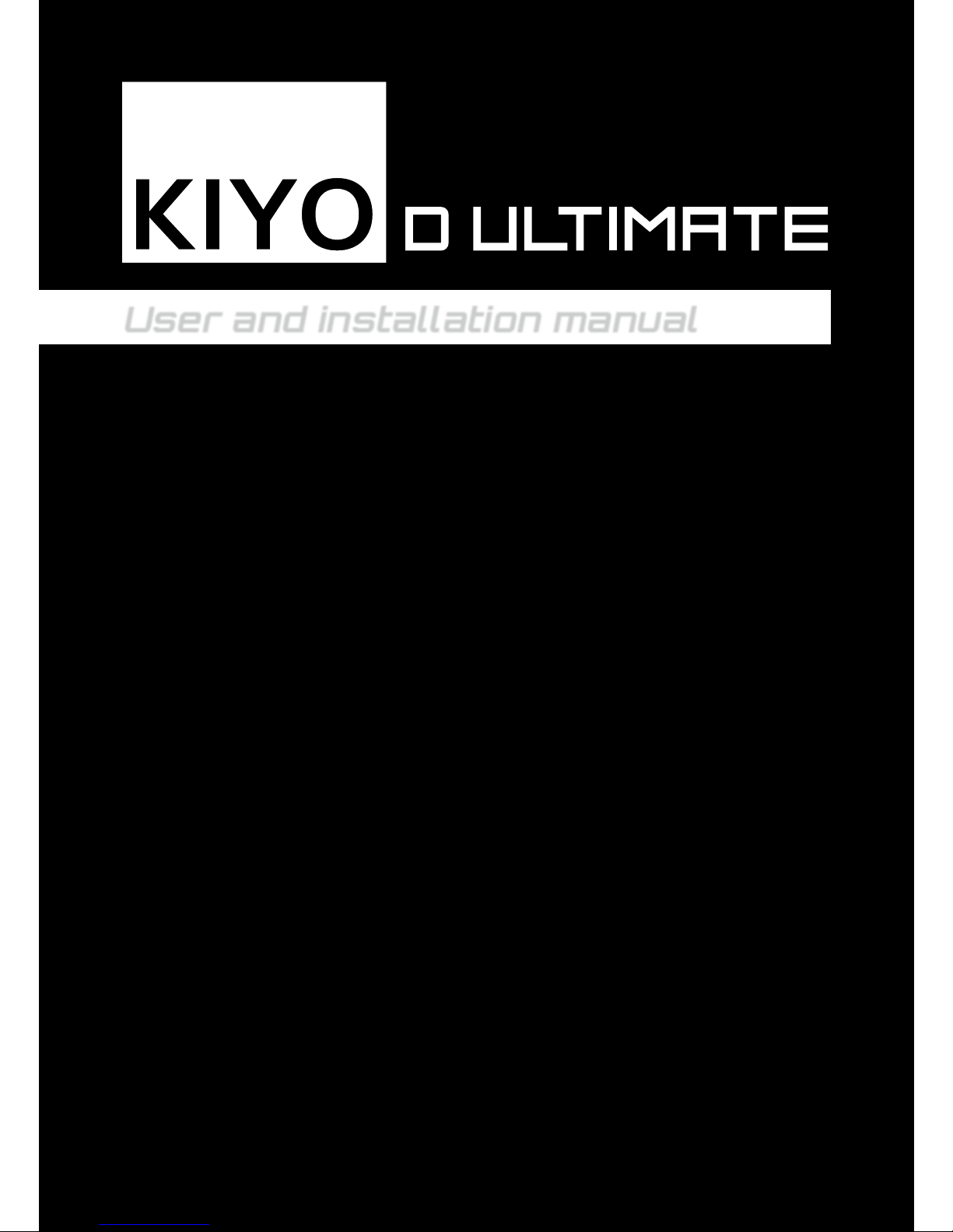
OPERATION OF THE KIYO D ULTIMATE SYSTEM
The dierent features of the KIYO D Ultimate system, like the USB updatability, the
external speaker, the LED indicator and the sensors built into the license plate frame
make the completely stealth installation possible.
There is no need to activate the modules one by one, because the system is connected
directly into the electrical system of the vehicle, therefore it switches on automatically
upon ignition, and when the engine is shut o, the system will also switch o. After the
installation and rst setup, the system will be ready to use immediately after ignition,
without adjusting the settings every time. The devices run a system check upon every
activation and in case of problem, the loudspeaker gives a warning signal and the LED
indicator starts ashing red. When the system check does not detect any problem, the
LED indicator ashes according to the currently selected mode and the loudspeaker
states the name of this mode as well.
Operation when detecting xed- or mobile LIDAR devices:
The sensors, built into the license plate frame, detect the signal of both xed- and
mobile LIDAR cameras. When the system detects a camera, dierent LED colors,
sound eects, and a warning voice draw the driver’s attention to imminent dangers.
When hearing these warnings, the driver has to cautiously adjust the speed of the
vehicle, while paying attention to the rest of the trac as well
Operation when detecting xed speed cameras:
The xed speed cameras are detected by the GPS U1 module of the system. Thanks to
its freely updatable Europe database, it is able to detect xed speed cameras, average
speed cameras, red light cameras and other trac enforcement devices. Depending on
its settings, the device can give LED and voice warnings even from a 750m distance.
Upon closing to a xed speed camera faster then allowed, the device warns the driver
to adjust the speed of the vehicle according to that specic zone.

2
Operation when detecting radar signals:
GPS- and laser detectors cannot detect radar-based speed cameras. These types
of devices can only be detected with the RAD U1 radar detector module, which can
identify the radar waves that these cameras emit.
Upon detecting a radar signal, the device warns the driver with dierent sound eects,
LED signals and voice alarms. The driver then has to adjust the speed of the vehicle
according to that specic zone, while paying attention to rest of the trac as well.
COMPONENTS OF THE KIYO D ULTIMATE SYSTEM
For the best eciency of the KIYO D Ultimate system, it is recommended to trust
experienced professionals with the installation of the system. For the proper operation
and eciency of the laser unit, the dierent components must be installed precisely,
furthermore, the number and position of the required sensors may vary in each vehicle.
Contact our customer service and we help you nd the closest ocial KIYO
TECHNOLOGY workshop!
8
3
1
2
6
7
5
4
1. KIYO GPS U1 xed speed camera detector module:
The KIYO GPS U1 device is the central unit of the KIYO Ultimate system, as it
processes the dierent signals of the other modules and warns the driver to imminent
dangers. The device comes with a display screen, but it can also be hidden under
the dashboard. Further information regarding the device itself and the installation, are
available in its user manual.
2. External speaker:
The external speaker is useful in case of stealth installation, as it amplies the
volume of the dierent warnings and ensures that the driver noticies the danger. The
loudspeaker can be connected to the GPS U1 with the Communication cable included
in the set.
3. Multi-colored LED indicator:
The LED indicator shows the current status of the complete system at all times and
warns the driver with dierent colored signals. It is useful in case of stealth installation,
because it is able to inform the driver about everything, therefore the GPS U1 unit can

3
be hidden under the dashboard. The LED indicator can be connected to the GPS U1
with the Communication cable included in the set.
4. External GPS antenna:
Although the GPS U1 has a built-in GPS antenna, in case of stealth installation (when
the device is installed under the dashboard) an external GPS antenna is required for
establishing connection with the GPS satellites. The GPS antenna can only operate
properly, if its upper side has a clear view to the sky.
5. RAD U1 radar detector module:
The RAD U1 module is able to detect the signals of both xed and mobile radar-based
speed cameras. The module connects to the GPS U1 unit and it can be installed
behind the plastic bumper of a vehicle. Further information regarding the installation
and operation of the module are available in the user manual of the device.
6. Central unit of the D Ultimate laser module:
The D Ultimate laser module connects to the GPS U1 unit with the Communication
cable included in the set. The power supply of the whole system in ensured by the
laser module, therefore it must be connected into the electrical system of the vehicle.
Further information regarding the steps of the installation are available in this manual.
The laser sensors in the license plate frame (7. and 8.) connect to the central unit
of the laser module. Further information regarding the installation, update and
operation of the laser unit are available in this manual.
WARNING! If the complete system is installed, the GPS U1 is powered through
the Communication cable of the D Ultimate module, therefore no power cable
may be connected to the GPS U1 directly, because it may disturb and damage
the electrical system of the vehicle!
Due to the laser-muting features of the GPS U1, the beeping sound of the
laser module must be terminated. To do this, the buzzer of the laser module
has to be removed or its wirings must be disconnected from the 10-pin socket.
If the complete system is installed, the LED indicator of the laser
module may remain hidden under the dashboard with the central unit,
because the GPS U1 unit will give the alarms to the driver.
The central unit of the laser module and the GPS U1 device must be updated
and congured separately at rst startup. In order to do this, always follow the
instructions found in the user manual and on the website of the manufacturer.

4
KIYO GPS U1
Short product description
The KIYO GPS U1 is a device that can detect xed speed cameras. In order to create a
complete defense system against speed cameras, it can be connected with a radar- and a
laser detector module. It receives and processes all of the other modules’ signals and warns
the driver to imminent dangers. The English speaking KIYO GPS U1 comes with a display
screen, but if needed, it can also be hidden under the dashboard of the vehicle.
Accessories of the KIYO GPS U1:
Velcro tape
Cigar lighter
power cable
USB cable User Manual
Radar Module (optional)
External GPS antenna (optional)
The device can be updated through an USB cable and a computer. After connecting the
optional Radar Module to the GPS U1, the system can detect the signals of radar-based
speed cameras as well. In case of stealth installation, the external GPS antenna ensures the
connection with the GPS satellites.
WARNING! The cigar lighter power cable of the GPS U1 device can only be
used if the GPS U1 operates as a separate detector. If it is connected with
the laser module, then it is powered through the Communication cable of the laser
module, therefore its power cable must not be connected!
Further information regarding the operation, installation and conguration of the GPS U1
and its radar module are available in the user manual of the KIYO GPS U1 device.

5
Communication cable and other accessories
Installation and operational information
To establish a complete system, the KIYO GPS U1 and the KIYO D Ultimate devices must
be connected with the Communication cable included in the package.
KIYO GPS U1 KIYO D Ultimate
Central Unit
Communication cable
The communication cable can be used with the KIYO GPS U1 device alone. In case of
stealth installation, the LED indicator of the Communication cable and the voice of the GPS
U1 will alert the driver to imminent dangers. Thanks to these features, the display screen of
the GPS U1 can be hidden under the dashboard or into the dierent compartments of the
vehicle. To amplify the volume of the alarms, an external speaker can be connected into
the mono jack socket of the cable.
2.1. 3. 4.
Parts of the communication cable:
1. Multi-colored LED indicator
2. External speaker socket
3. COM socket for the GPS U1
4. COM socket for the D Ultimate
central unit.
Another part of the communication cable is a 2-pin plug cable that allows two D Ultimate
central units to be connected in series. In this way, the laser unit can be expanded up to 8
sensors. The KIYO D Ultimate laser unit can process
that two central units are connected in series. The
central unit that is connected directly into the laser unit
will handle the frontal sensors, while the next central
unit will handle the rear sensors. This is important when
the device states the direction from which the signals
are detected. (In case of one CPU, the frontal sensors
must be connected to ports 1 and 2, while the rear
sensors must be connected to ports 3 and 4.)

6
KIYO D ULTIMATE
Laser Module
User and installation manual
The KIYO D Ultimate is an active laser detector, developed and manufactured in Hungary,
especially for European markets. With its laser sensors (hidden into the special license
plate frame), it is able to detect most of the European speed cameras and it can be installed
quickly and easily. The device is freely updatable via USB, therefore it can always be up
to date.
The sensors in the license plate frame detect the signals of both xed- and mobile LIDAR
speed cameras. When the GPS U1 device is connected, voice alarms, sound eects and
LED warnings alert the driver to speed cameras. However, the laser detector can operate on
its own. In this case, LED lights and beeping sounds will alert the driver.
In case of an alert, the driver has to adjust the speed of the vehicle, while paying attention
to the rest of the trac as well.
MODES OF THE KIYO D ULTIMATE LASER DETECTOR
The dierent modes of the device can be set with a three-way switch. In position II.
the device is in active mode, while in position I. it is in passive mode. In position 0.
the device is turned o. When the GPS U1 is connected, it will state the name of each
modes upon starting the system or changing between modes.
Three-way switch
Position II. : ACTIVE MODE
Position 0.: OFFLINE
Position I. : PASSIVE MODE
Panic button:
With the hidden panic switch, the device can be deactivated
at any time and can only be used as a parking assist.
Only the distributor can reactivate the device, therefore
it is recommended to avoid using the panic button!
Push and hold the switch to deactivate the system, a short
beeping sound indicates that the process has started
and a longer beeping sound is heard when it is nished.

7
Central unit Sensor (2 / 4 pieces) USB extension cable
Pendrive Plastic card Hex key
License plate frame (1 / 2 pieces)
COMPONENTS OF THE KIYO D ULTIMATE LASER DETECTOR:
Power cable

8
INSTALLATION OF THE LASER UNIT:
The operation and eciency of the laser detector depend on the number of sensors
used, their precise installation and proper aligning. The structure and size of the vehicle
determine the number of the required sensors.
One central unit can handle up to 4 sensors, however, bigger vehicles and the detection
of special speed cameras may require 6-8 sensors. In these cases, another central unit
must be connected to the system with extra power- and communication cables. It is
recommended to trust ocial workshops with the determination of the required sensors
and the installation of the device. Contact our customer service and we help you nding
the nearest workshop!
1-2. Installing the license plate frame and the sensors:
The sensors must be placed into the special, infrared-transmitting license plate frame
included in the set. During installation, the original frame has to be replaced with this
special frame and then the wirings of the sensors must be led to the cabin of the vehicle
and connected into the central unit (3).
Sensors
3
9
4
8
6
7
12
5

9
If the license plate frame of the vehicle is angled, then for the best eciency, the sensors
have to be aligned to be parallel with the road. The angle of the sensors can be adjusted
with the screw on the side of the mounting bracket.
To maintain the optimal detection eciency, the license plate frame must be kept clear
of mud, bugs and other contaminations. There may be situations, when the device
signals too late or not at all (f.e.: strong solar radiation, refraction, rainy weather, snow,
contaminated sensors).These are not caused by the malfunction of the device, but by the
law of physics.
a) Remove the original license plate frame of the car!
b) Try on the special license plate frame to the car.
The thicker part of the frame holds the sensors and for the best aesthetic view, ensure
that this part goes to the bottom. If the license plate is fastened to the bumper, you may
put the sensors to the upper part of the frame, to be closer to the middle of the car.
Horizontal road
Adjusting
screw
Sensor
Mounting
bracket
►
►
►
Fastening screw ►

10
c) If the license plate frame of the vehicle is angled, then for the best eciency, the sensors
have to be aligned to be parallel with the road. The angle of the sensors can be adjusted
with the screw on the side of the mounting bracket.
Remove the sensors from the special frame and fasten it to the vehicle. With a double-
sided tape, fasten the sensors to the outer panel, which is parallel to the inner panel of
the frame. There you can align the angle of the sensors properly. After aligning them to
horizontal, fasten the angle with the fastening screw on the side of the bracket.
d) After following the steps of removing the frame, mounting the sensors and then
reattaching the special frame, the sensors will be aligned to horizontal and the license
plate can be put back.
e) Find a suitable position for the central unit under the dashboard of the vehicle!

11
f) Lead the sensor cables into the cabin, but pay attention that they cannot touch any
rotating, moving or sharp parts, or hot surfaces (radiator, fan, engine block, etc.)! Do
not stretch the cables too much, but they cannot be too loose either. Fasten the cables
with cable ties or with electrical tape! Never knot or break the cables, because damaged
cables may lead to malfunction of the device and to the loss of warranty!
g) Connecting the sensors to the central unit:
GPS U1 D CPU
Communication cable
In case of a 4-sensor system, only one central unit is needed. If a GPS U1 device is
connected to the system, the frontal sensors must be connected to ports 1. and 2., while
the rear sensors go to ports 3. and 4.
GPS U1 Primary CPU Secondary CPU
Communication cable
Series connection cable
In case of a system with 6 or 8 sensors, two central units are needed. If you use them
with a GPS U1 device, then the two CPUs must be connected with the communication
cable of the set.
After it, choose which unit will be the primary CPU (does not matter which), and connect it
to the GPS U1 device. The frontal sensors must be connected to the primary CPU, while
the rear sensors go to the secondary CPU. This is important when the device states the
direction from which the signal comes
In case of two central units, it is recommended to use the power cable distributor that can
be bought separately. With this, only one of the power cables connect to the electrical
system of the car and the distributor powers the other unit.
If a GPS U1 device is connected to the system, it is forbidden to connect
the cigar lighter power cable, because it may disturb and damage the
electrical system of the vehicle!

12
Connecting the power cable
4. Mode switch:
Install the mode switch on- or under the dashboard, where you can reach it while
driving. If the size of the switch is right, tt is recommended to place the switch into an
empty slot on the dashboard.
5. Power supply wiring:
RED: constant +12V. In order to avoid accidential panic button use, the fuse of the red
wire is removed when packaging the device. After nishing the installation, place the
fuse back to the wire!
YELLOW: ignition +12v. The yellow wire has to be connected to the +12V wire that is
powered upon ignition.
BLACK: ground wire, which goes to the body of the car or to the negative terminal of
the battery.
6. Buzzer:
When only the laser detector is used, the buzzer below the dashboard warns the driver
with sound alarms. If the GPS U1 device is connected to the system, the buzzer must
be removed from the wiring either by disconnecting the 10-pin plug or by cutting and
insulating them separately. It is needed, because the sound alarms will be given by the
built-in loudspeaker of the GPS U1 or by the external loudspeaker. Furthermore, in a
complete system, the false alarm ltering features can only work this way.
7. Two-colored LED indicator:
When only the laser detector is used, the LED indicator (placed in the lower corner
of the A column on the driver’s side) will show the alarms. If the GPS U1 device is
connected to the system, this LED indicator may remain hidden under the dashboard
or can be removed, because the alarms will be given by the communication cable’s
LED indicator.
8. Panic button
The panic button must be placed where the driver cannot push it accidentally. It is
recommended to place it under the dashboard, where it cannot be reached by the
driver’s legs.
4
5678

13
9. USB extension cable:
The USB extension cable must be installed to an easily accessible place, because
in case of updating or conguring the settings, the pendrive will be connected to this
cable. If there are two CPUs, then both USB extension cables have to be accessible,
as the CPUs have to be updated separately. Recommended installation place is the
glove compartment.
CONFIGURATION AND SOFTWARE UPDATE OF THE LASER UNIT:
The KIYO D Ultimate laser unit can be congured and its software updated with the help of
a pendrive and a computer. The setup and update software can be downloaded from the
website of the manufacturer: https://kiyotechnology.com. After updating the software,
some feature of the device may dier from what is written in this manual.
ALARMS OF THE KIYO D ULTIMATE:
When only the laser unit is used, the device communicates with LED lights and beeping
sounds. If the GPS U1 is connected, voice alarms of the selected language clarify the
dierent warnings.
Warning! Some of the alarms may change with new software updates!
• Short beeping sound, continuous GREEN light: the device is ready to use in active
mode.
• Three beeping sounds and ashing GREEN light: the device is ready to use in
passive mode.
• Rhythmical beeping sound and ashing RED light: obstacle detected in parking
assist mode.
• Rhythmical beeping sound and ashing RED and GREEN light: laser detection alert.
• Change in the rhythm of the laser detection alert: The active mode timer has expired
and the device changed back to passive mode. After the reset time, a beeping sound
indicates that the device is in active mode again.
• Silent, ashing RED and GREEN light: unknown laser detection alert, with muted
sound.
• Crackling beeping sound and ashing RED and GREEN light: unknown laser
detection alert, with enabled sound
• Silent, continuous RED light: The pendrive is still connected after the last update
(so the device is not ready to use), or the system is deactivated with the panic button.
• Continuous beeping and RED light: no sensor connected.
• Silent, quickly ashing RED light: update in progress.
• Silent, slowly ashing RED light: corrupted or no update le can be found on the
pendrive.
• Continuous RED light and repeating beeping sounds:.One of the sensors may be
malfunctioning, the number of the repeating beeping sound indicates the number of the
port where the damaged sensor is connected.

Popular Automobile Accessories manuals by other brands

Sierra
Sierra Convertible Top installation guide

Hamron
Hamron 016040 operating instructions

Auto Care Products
Auto Care Products Park Smart Clean Park quick start guide

Swagman
Swagman XC 2 instruction sheet

Metra Electronics
Metra Electronics 99-7326 installation instructions

iOttie
iOttie One Touch 2 installation instructions