Configuration
The USB-485 has no switch or software configuration. The only customisable features are whether the RS4xx
driver is to be be permanently enabled (for RS422 point to point systems, or for use as a Master on a 4-wire RS485
multidrop system) or whether the RS4xx receiver is to be forced to be permanently enabled for receipt of all
transmitted data (usually this is for RS422 point to point systems). These selections are done by grounding pins 9
and 5 respectively. The selection of baud rate and character format is done by the Windows application program.
Power Requirements
The USB-485 is powered entirely from the USB interface. It contains an isolated inverter which powers the isolated
RS422/485 interface. The USB power consumption depends somewhat on the RS4xx cable/terminator loading; the
90mA is the worst case with a 100 ohm terminator. However, if connecting several USB-485 converters to a hub,
the hub may need to be a powered hub because many laptops do not have the full-spec (500mA) USB ports.
Software Drivers
A driver is required within the operating system, to create the virtual COM port. There are two main vendors of
USB-serial chips on the market: Prolific and FTDI. Most USB-RS232 converters on the market, including the KK
Systems USB-232, use the Prolific chip and drivers. Nearly The USB-485 uses the FTDI chip and drivers, so if you
are using one of the other converters you will still need to install the new FTDI drivers which are enclosed with this
product. Furthermore, most of the Prolific-based products do not have a unique USB device identifier and plugging
them into different USB ports generates new COM port numbers.
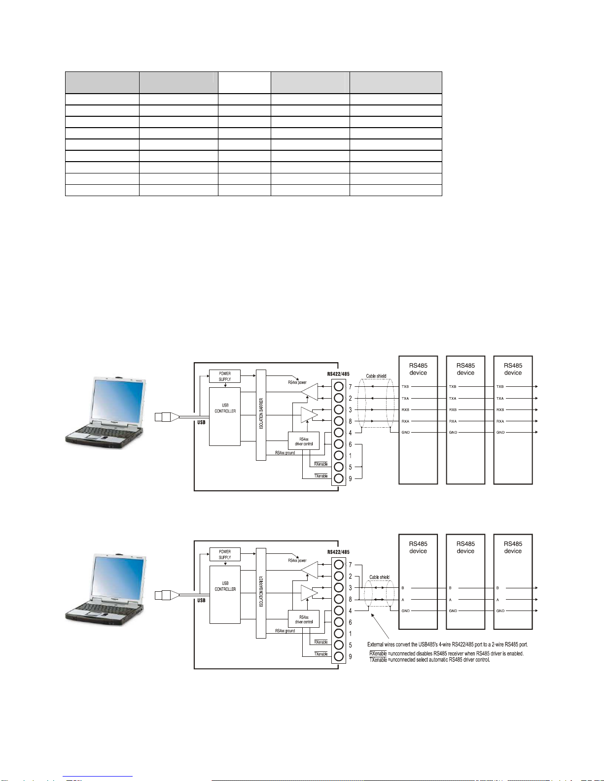
RS485 Driver/Receiver Control
The USB-485 performs automatic driver enable (ADE) automatically, enabling the RS485 driver for each
transmitted character. There is no need for your application software to provide RTS Control of any kind. This is
overriden by grounding pin 9 of the DB9 connector which permanently enables the driver, for RS422 (or 4-wire
RS485 Master) applications.
The USB-485 RS4xx receiver is disabled when the transmitter is enabled. If this is not desired (for full-duplex
usage e.g. RS422), connect pin 5 of the DB9 connector to ground.
Terminators
These are not normally needed for cable runs under 300 metres. The following diagrams show where they should
be connected. The resistor value should equal the characteristic impedance of the cable - typically 100-120 ohms
for proper grade RS422/485 cable.