Klein 3000 Series User manual

Klein 3000 Side Scan Sonar
Telemetry Faults
Although the Klein 3000 Side Scan Sonar is an extremely reliable system,
because it is used in a physically demanding environment occasional problems
do arise. The most common problem encountered by any Side Scan Sonar
system is the telemetry fault. This would be the communication via coaxial
connections between the TPU and the Towfish. There are different causes and
different degrees of severity of a telemetry fault. The following troubleshooting
steps are recommended for the Klein 3000 Side Scan Sonar in order of
complexity beginning with the most basic fault.
The symptom of a telemetry fault is, with the TPU connected to the
Towfish via the deck cable, winch slip ring and tow cable and with the computer
and TPU properly configured, the towfish will not come up. The indication is
the two yellow LED’s on the Demultiplexer PCB stay illuminated after the normal
boot time (approximately one minute). This indicates failure of the data
communication between the TPU and Towfish. If this should happen, de-
energize the TPU and follow the below steps in order:
1) Although the Klein 3000 Side Scan Sonar is a complex electronic device,
the telemetry connection between the Towfish Type N Connector on the
TPU and the 8 pin connector on the Towfish bulkhead is a simple single
conductor with shield 50 ohm coaxial cable connection. Check all of the
connections between the TPU and the Towfish confirming that they are
properly seated. Check the entire length of the cable for damage.
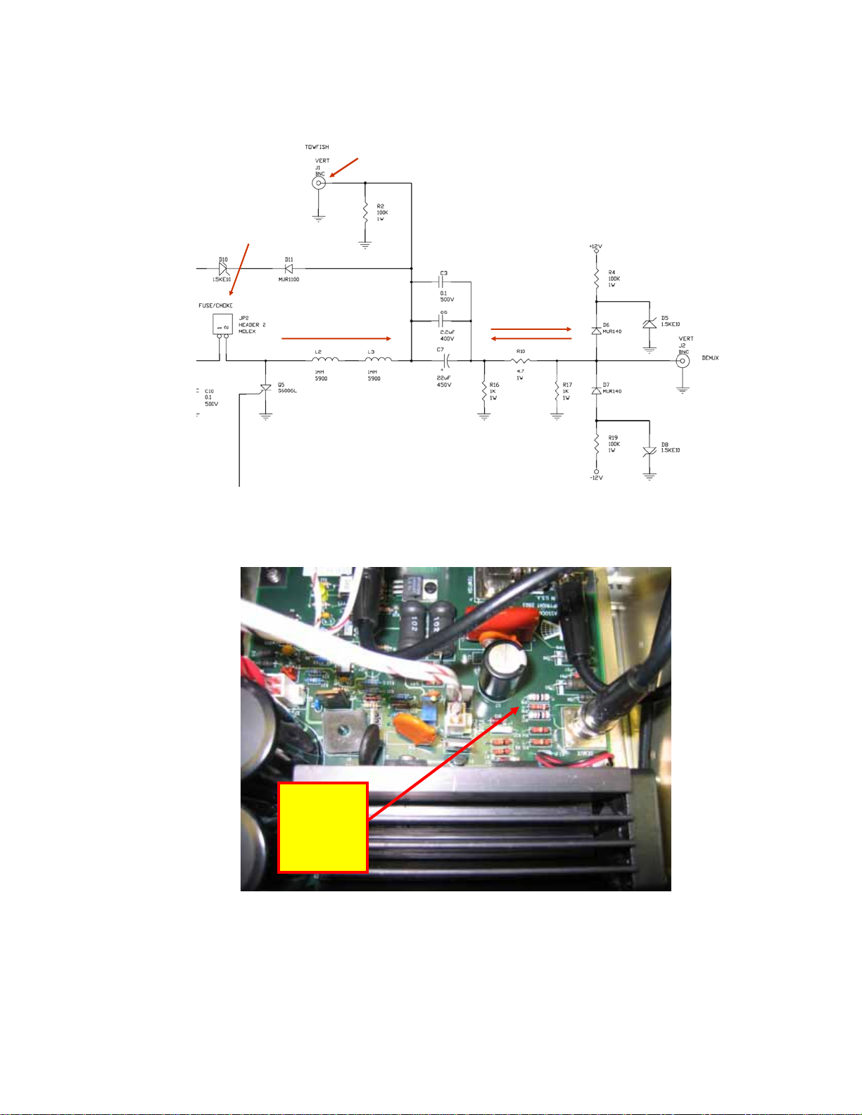
2) If all of the connections are secured, using a DVM measure the DC
Voltage (approximately 200 VDC) at the following points:
a. The Type N Connector on the back of the TPU. Carefully measure
across the center pin and the outside shell. If the 200 VDC is not
present, remove the Towfish Fuse on the back of the TPU and
replace it if necessary. This may correct your problem.
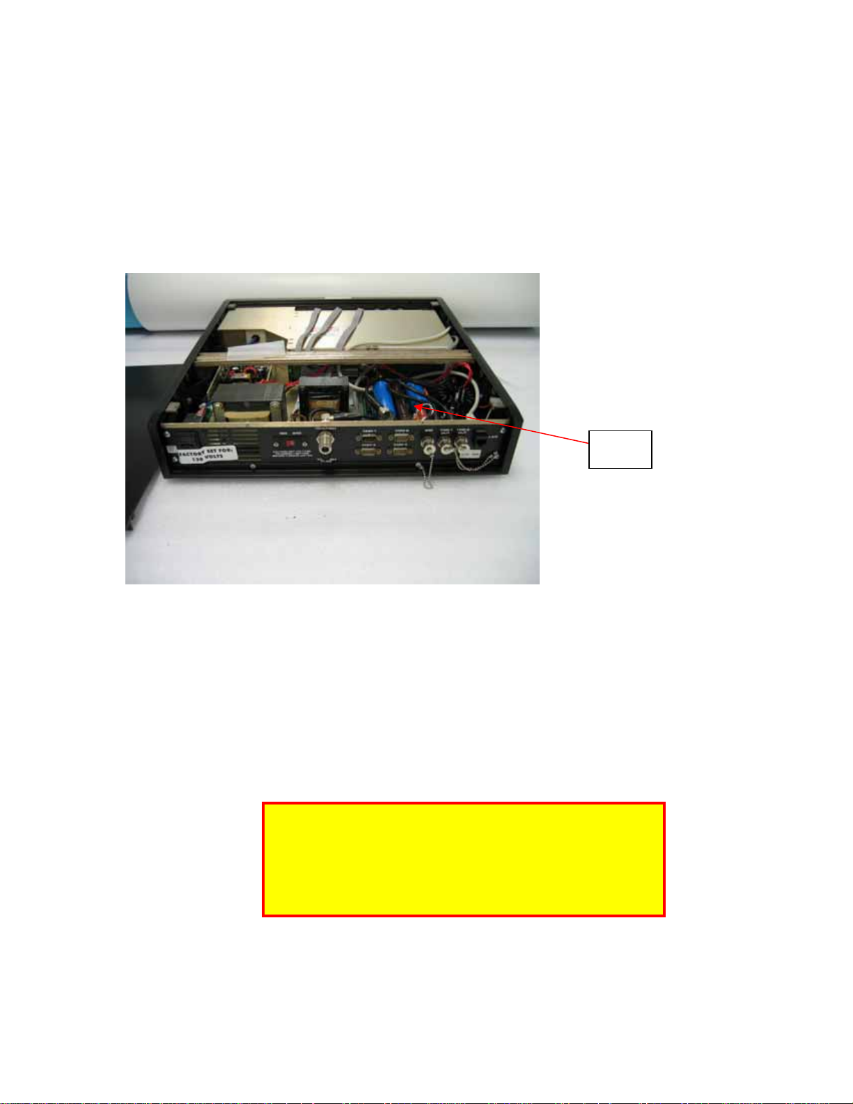
Note:
If you measure the 200 VDC at an excessive value
such as 275 VDC and the voltage switch on the
back panel of the TPU is set properly for 115 VAC
or 220 VAC depending on your voltage source,
contact Klein for technical support. Do not run
the equipment if the voltage is more than 10%
above normal operational voltage of 200 VDC.
This symptom indicates a possible failure of the
TPU 200 VDC Power Supply.

b. If the 200 VDC is present on the Type N Connector, reconnect to
the Type N Connector and continue checking for the 200 VDC.
Confirm that it is present at the end of the tow cable or the deck
cable (depending on configuration). If using a winch, confirm that
the 200 VDC is present at the input to the slip ring and at the end of
the winch tow cable. The final check should be at the input to the
Towfish.
Note:
The faults described below in relation to
R11 on the TPU 200 VDC Power Supply PCB (R10
on newer Universal Power Supply PCB’s, Klein PN
14103210) and R30 on the Towfish Multiplexer
PCB are normally caused when the tow cable
breaks with the TPU energized or could be caused
if the tow cable is disconnected with the TPU
energized. If proper care is taken to shut down
the system completely before disconnecting the
tow cable at any point in its run between the Type
N Connector on the TPU and the bulkhead
connector on the Towfish, the occurrence of this
fault should be minimized. Whenever the TPU is
energized and connected to the Towfish, the
Towfish is energized.
3) Assuming that the 200 VDC is present at the input to the Towfish, that
the Computer and the TPU are properly configured and the Cable
Type N
Connector
Center Pin

BNC is connected to the front of the Demultiplexer PCB, the following
steps can be taken, assuming a degree of technical competency:
a. Removing the two screws that hold the locking bar on the rear of
the TPU, slide the locking bar back to remove the top cover from
the TPU exposing the TPU Power Supplies and the 200 Volt
Transformer.
b. On the TPU Power Supply PCB, Klein Part Number 14102048,
measure R11, Klein Part Number 12100547 with a DVM. It should
read 4.7 ohms. If it reads open or a high value resistance, it should
be replaced. Use a resistor supplied by Klein or an equivalent 4.7
ohm, 1 watt resistor of proper physical size.
c. If you replace R11 the PCB should be removed. Use extreme
caution in removing this PCB. Mark all connectors and be
careful to reconnect them to the proper place when the PCB is
reinstalled.
R11
Note:
On newer Universal Power Supplies, measure R10.
See the note at the end of this document for
information on R10.

d. If after replacing R11, the Towfish boots up, however you observe
deteriorated performance, it is possible some other components
may have been damaged.
e. Using the below partial schematic of the TPU 200 VDC Power
Supply PCB as a reference, replace D7, D8, D9 and D10. Also
ohm out R9 and R10 to confirm proper value. Replace R9 and/or
R10 if the value is not correct.
R11

f. D7 and D8 are Klein Part Number 12000113
D9 and D10 are Klein Part Number 12000100
R9 and R10 are Klein Part Number 12100006.
4) If R11 on the TPU 200 VDC Power Supply PCB is the correct value and
again assuming that the 200 VDC is present at the Towfish and the
Computer and TPU are properly configured, the following steps can be
taken.
a. Referring to Section 4.22 on page 4-38 of the 3000 Troubleshooting
Guide for instructions on removing the electronics package from the
Towfish. If you havn’t already done so, after removing the Nose
Cone from the Towfish, disconnect the Towfish Jumper Cable on
the Bulkhead and check for 200 VDC across pins 1 (200 VDC) and
2 (Return) using a DVM. If the 200 VDC is not present, replace
the 39 inch Towfish Jumper Cable. If it is present continue to b.
b. After removing the electronics package, find R30 on the Multiplexer
PCB, Klein Part Number 14102051. R30, Klein Part Number

12100547, should measure 4.7 ohms and is a 1 watt resistor. If it
is open or a significantly higher value, replace it.
R30
Note:
On the newer Universal Power Supply, Klein PN
14103210, R10 should measure 4.7 ohms, 1 watt.
See the partial schematic and photo below for
reference.

Data to/from
Demultiplexer PCB
200 VDC to Towfish
Goes to 630 ma fuse
on back panel of the
TPU
Goes to Type N connector on the
back panel of the TPU
R10 =
4.7
ohms,
1
watt
Other manuals for 3000 Series
2
Table of contents
Other Klein Test Equipment manuals
Popular Test Equipment manuals by other brands

Westinghouse
Westinghouse AMPTECTOR Instruction leaflet

Ossila
Ossila T2003 user manual

WHALETEQ
WHALETEQ CMRR 3.0E user manual

DelAgua
DelAgua Portable Water Testing Kit user manual

Gemini
Gemini Tinytag Energy Logger Technical manual

Keysight Technologies
Keysight Technologies InfiniiVision 1000 X-Series Service guide