Kleinn Air Horns RNGR-102-1/220 User manual

Go to Table of Contents
REV: IR 02/15/2022
3
RNGR-102-1/220
Installation & Operation Manual
Table of Contents
1 How to Use This Manual.....................................................................................................................................5
1.1 Interactive Manual Using Adobe Reader....................................................................................................5
1.2 Your SKU Number & this Manual ...............................................................................................................5
1.2.1 RNGR-102-1/220.................................................................................................................................5
1.2.2 Warranty Registration ........................................................................................................................5
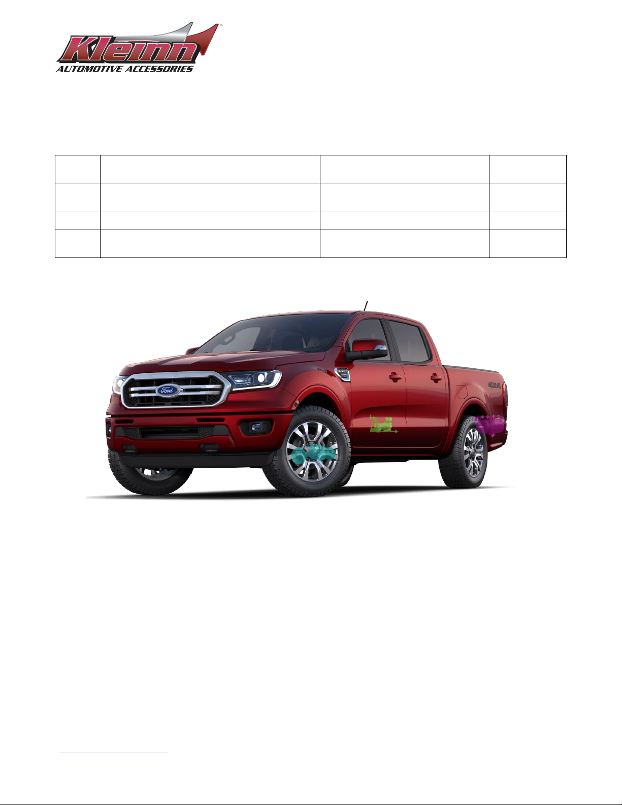
1.3 Illustration/Photo Details & Orientation....................................................................................................6
2 Safety First ..........................................................................................................................................................6
3 Application Chart................................................................................................................................................7
3.1 Bolt-On Vehicle List ....................................................................................................................................7
3.2 Excluded Vehicles .......................................................................................................................................7
3.3 Aftermarket Product Compatibility............................................................................................................7
4 Installation Overview..........................................................................................................................................8
4.1 Kit Layout & System Location(s).................................................................................................................8
4.2 Install Process Outline ..............................................................................................................................10
4.3 Approximate Installation Time .................................................................................................................11
5 List of Tools & Supplies.................................................................................................................................... 12
5.1 Standard Tool List (Required) ...................................................................................................................12
5.2 Special Tool List (Recommended) ............................................................................................................12
5.3 Shop Consumables List (Recommended) .................................................................................................12
6 Parts List .......................................................................................................................................................... 13
6.1 Review Parts List.......................................................................................................................................13
6.2 Pre-Packaged Kit Items.............................................................................................................................13
6.3 Air Fittings & Related Items......................................................................................................................14
6.4 Electrical Components & Related Items...................................................................................................15
6.5 Mounting Brackets & Special Hardware...................................................................................................16
6.6 Hardware, Fasteners, & Soft Parts ...........................................................................................................17
7 Bench Assembly............................................................................................................................................... 18
7.1 Assemble Air Fittings to Air Tank..............................................................................................................18
7.2 Assemble Air Tank to Tank Brackets.........................................................................................................19
7.3 Assemble Air Filter to Air Compressor .....................................................................................................19
7.4 Assemble Air Compressor to Compressor Bracket...................................................................................20
7.5 Disassemble Trumpets from Air Horn Drivers..........................................................................................21

Go to Table of Contents
REV: IR 02/15/2022
4
RNGR-102-1/220
Installation & Operation Manual
7.6 Assemble Air Horn Driver to Horn
Bracket..................................................................................................................................................................21
8 On-Vehicle Assembly, Mechanical .................................................................................................................. 22
8.1 Install Air Tank on Vehicle ........................................................................................................................22
8.2 Install Air Compressor on Vehicle.............................................................................................................23
8.3 Install Horns on Vehicle............................................................................................................................24
8.4 Route Air Hose and Install Remote Quick-Connect Coupler ....................................................................25
9 On-Vehicle Electrical Installation..................................................................................................................... 26
9.1 Relay & Fuse Diagram for Air Horn System ..............................................................................................26
9.2 Disconnect Vehicle Battery(s)...................................................................................................................27
9.3 Connect Wires to Fuse & Relay ................................................................................................................27
9.4 Install Horn Button ...................................................................................................................................27
9.5 Connect Pressure Switch ..........................................................................................................................28
9.6 Connect Air Compressor...........................................................................................................................28
9.7 Connect Air Horn Solenoid(s) ...................................................................................................................28
9.8 Secure Wiring to Vehicle ..........................................................................................................................28
10 Final Steps & Testing ................................................................................................................................... 29
10.1 Reconnect Vehicle Battery(s) ...................................................................................................................29
10.2 Test Air Compressor .................................................................................................................................29
10.3 Test Train Horns........................................................................................................................................29
10.4 Test Quick Connect Coupler .....................................................................................................................29
11 General Operation....................................................................................................................................... 30
11.1 Compressor Operation .............................................................................................................................30
11.2 Horn Operation.........................................................................................................................................30
12 Routine Maintenance .................................................................................................................................. 30
13 Warranty Information ................................................................................................................................. 31
14 Record of Revisions ..................................................................................................................................... 32
END OF TABLE OF CONTENTS

Go to Table of Contents
REV: IR 02/15/2022
5
RNGR-102-1/220
Installation & Operation Manual
1How to Use This Manual
1.1 Interactive Manual Using Adobe Reader
It is recommended to open this digital PDF using Adobe Reader® to take advantage of following key features:
•Hyperlinks (blue underlined text) allow access to additional content via internet; click/tap to activate.
Hyperlinks also allow users to jump to specific spots in within the document.
•Includes Installation Figures and “Figure xx”
•Table of Contents page allows easily navigating this manual; click/tap any section line to go to it
•Bookmarks allow quick navigation to any section; click/tap
•Zoom IN on pictures by pressing “CTRL and +” at same time on PC, or pinch in on smart devices
Zoom OUT on pictures by pressing “CTRL and -” at same time on PC, or pinch out on smart devices
To Download & Install Adobe Reader®
On PC or Mac:
•Visit https://get.adobe.com/reader/otherversions/
On Android/iOS, and Windows devices:
Visit https://get.adobe.com/reader/otherversions/
1.2 Your SKU Number & this Manual
This manual covers the installation, testing, and operation of following SKU part numbers
1.2.1 RNGR-102-1/220
NOTE: Illustrations and pictures contained herein may represent only one kit part number.Where
critical differences exist between kits, (i.e., different parts, orientation, mounting points, etc.) additional
text, or necessary graphics are provided to minimize confusion.
Parts list explicitly state kit differences with (BOLD TEXT) inside parenthesis, shown below part number
1.2.2 Warranty Registration
Please register your kit online at https://kleinn.com/warranty/ to expedite any future warranty claims.

Go to Table of Contents
REV: IR 02/15/2022
6
RNGR-102-1/220
Installation & Operation Manual
1.3 Illustration/Photo Details &
Orientation
This manual may use digitally created illustrations and/or actual photos of example vehicle. These graphics may
not include exact items found on your vehicle (i.e., electrical wiring, fuel lines, body panels, etc.). Illustrations
typically will be missing details and are for clarity to show critical mounting locations and orientation on vehicle.
Throughout the manual, yellow arrows with text reading “FRONT” may be
present over illustrations and pictures. These arrows specify direction
toward the front of the vehicle and provide clarity as to how illustration is
viewed.
END OF SECTION
2Safety First
Read manual thoroughly before starting installation of this kit. Verify that you have all parts listed, and that you
clearly understand the installation procedure. Contact Kleinn technical support with any questions.
Installation of this kit requires moderate mechanical aptitude; seek professional help if you’re not competent
using hand tools in tight uncomfortable spaces and around possibly rusted and sharp vehicle parts.
Before starting, obtain proper tools required to perform installation correctly, adequate lighting, eye protection,
hearing protection, (for operating train horns) and hand protection to guard against sharp edges and metal
burrs which may be present on kit parts and/or vehicle parts.
Throughout this manual the following words may be used; be aware of their meaning and application.
CAUTION: means damage could occur to vehicle or kit parts during or after installation.
WARNING: means injury could occur to you or others, including damage to vehicle or kit parts.
DANGER: means serious injury or death could occur to you or others during installation.
END OF SECTION
FRONT

Go to Table of Contents
REV: IR 02/15/2022
7
RNGR-102-1/220
Installation & Operation Manual
3Application Chart
3.1 Bolt-On Vehicle List
RNGR-102-1/220 is a direct-fit bolt-on air horn system for the following vehicles.
MODEL YEAR
MODEL
DRIVE
ENGINE
BODY
TRIM
2019-2021
Ranger
All
All
All
All
NOTE: All vehicles listed may require drilling holes for ground wires and installing switches, based on
preference of installed switch locations and wire grounding points.
3.2 Excluded Vehicles
The following vehicles have been found to be incompatible with the designed kit:
No incompatible configurations are known at this time.
3.3 Aftermarket Product Compatibility
This kit has been designed to work with the following aftermarket products:
•Power running boards/steps
•Fix running boards/steps
This kit has not been designed to work with the following aftermarket products:
•No incompatibilities are known at this time.
NOTE: Review this manual in full before unpacking items to verify correct space and mounting locations
exist with your aftermarket product(s). To install this kit alongside your other aftermarket product(s),
modification to the included parts, your vehicle, or your aftermarket product(s) may be required.
END OF SECTION

Go to Table of Contents
REV: IR 02/15/2022
8
RNGR-102-1/220
Installation & Operation Manual
4Installation Overview
4.1 Kit Layout & System Location(s)
RNGR-102-1/220 consists of the following components, located on vehicle as follows:
ITEM DESCRIPTION VEHICLE LOCATION
APROX.
INSTALL TIME
1
6275RC Air Compressor (102-1 KIT)
6450RC Air Compressor (220 KIT)
Passenger-side rear bed pocket 1 hr.
2 1.5 Gal. Air Tank Driver-side rear bed pocket 2 hrs.
3
102-1 Air Horns (102-1 KIT)
220 Air Horns (220 KIT)
Under cab 2 hrs.
Figure 1: Isometric Overlay of Kit Locations

Go to Table of Contents
REV: IR 02/15/2022
10
RNGR-102-1/220
Installation & Operation Manual
Figure 4: Under Vehicle View (Air Tank) – Behind Rear Wheel Well (Driver Side)
4.2 Install Process Outline
For person(s) with prior experience installing RNGR-102-1/220, a reminder of the install steps is provided
below:
UNPACKAGE KIT (SECTION 6)
1. Layout and organize all parts
BENCH ASSEMBLY (SECTION 8)
2. Assemble air fittings to air tank
3. Assemble air filter to air compressor
4. Attach compressor to compressor bracket
5. Attach air tank to tank brackets
6. Assemble horn (DRIVERS)to horn bracket
ON-VEHICLE MECHANICAL ASSEMBLY (SECTION 9)
7. Mount compressor bracket to vehicle
8. Mount tank brackets to vehicle
9. Mount horn bracket to vehicle
10. Attach horn trumpets to the horn drivers (220KIT ONLY)
11. Connect pneumatic components & route air tubing
ON-VEHICLE ELECTRICAL ASSEMBLY (SECTION 10)
12. Install relay & fuse, route wiring, and install horn button
13. Connect all electrical items (air horn(s), pressure switch, air compressor)
FINAL STEPS (SECTION 11)
14. Test system; adjust as needed

Go to Table of Contents
REV: IR 02/15/2022
11
RNGR-102-1/220
Installation & Operation Manual
4.3 Approximate Installation Time
RNGR-102-1/220 is a multi-faceted product consisting of mechanical, electrical, and pneumatic components.
For a typical home mechanic, auto enthusiast, or technician installing this kit for first time; a professional
installation job with setup and testing of final product, is estimated to take:
•5 hrs.
END OF SECTION

Go to Table of Contents
REV: IR 02/15/2022
12
RNGR-102-1/220
Installation & Operation Manual
5List of Tools & Supplies
5.1 Standard Tool List (Required)
1. Basic mechanic’s 3/8” drive socket sets with extensions
•Inch size sockets
•Metric size sockets
2. Basic mechanic’s combination wrenches (box/open-end)
•Inch size sockets
•Metric size sockets
3. Universal Joint Socket Adapters
4. Basic mechanic’s screwdriver set (Philips, Flat Head)
5. Diagonal cutter/wire cutter pliers
6. Wire strippers
7. Wire terminal crimpers
8. Slip-joint pliers
9. Vise grips or locking pliers
10. Small pry bar or large flat blade screwdriver
11. Utility knife or utility razor blade
12. Magnetic retrieval tool
5.2 Special Tool List (Recommended)
1. Power hand grinder, pneumatic grinder with cut-off wheel, or hacksaw
2. 10-100 ft-lbs. torque wrench
3. 20-150 in-lbs. torque wrench
4. Multi-meter for 12V DC electrical systems or equivalent
5. 12V DC test Light or equivalent
6. Trim panel tool, for removing wiring and body clips, when needed
5.3 Shop Consumables List (Recommended)
1. Quality electrical tape
2. Dielectric grease for electrical connections
3. Heat shrink tubing for electrical connections
4. Medium-strength thread-locker (i.e., Blue Loctite® PN 242) or equivalent
5. Low-strength thread-locker (i.e., Purple Loctite® PN 222) or equivalent
6. Black/Clear silicone for drilling holes in body
7. Sandpaper or wire brushes for installing ground wires
8. Extra plastic zip ties > 6” long
9. Extra NPT sealant (i.e., Kleinn Air Horn Juice, Teflon tape, etc.)
10. Touch-up paint for frame/chassis/body (i.e., primer or black epoxy)
11. Typical cleanup supplies
END OF SECTION

Go to Table of Contents
REV: IR 02/15/2022
13
RNGR-102-1/220
Installation & Operation Manual
6Parts List
6.1 Review Parts List
Unpackage and organize kit across a large work area and verify all parts are included, as listed below.
Contact Kleinn support with any questions.
1. Review pre-packaged kit items (K_)
2. Review Air Fittings and Tubing (F_)
3. Review Wiring and Accessories (E_)
4. Review Bolt-On Mounting Brackets (C_)
5. Review Hardware/Fasteners (H_)
6. Review Add-On Accessories (X_)
7. Familiarize yourself with how the parts assemble
6.2 Pre-Packaged Kit Items
NOTE:Items in this section come in their own packages and may include additional items inside package.
ITEM
QTY
PART NUMBER
DESCRIPTION
PICTURE
K1
*1
6275RC
(102-1KIT ONLY)
6275RC Compressor Kit,
with included hardware,
and remote air supply line
K1
*1
6450RC
(220KIT)
6450RC Compressor Kit,
with included hardware,
and remote air supply line
K2
*1
102-1
(102-1KIT ONLY)
102-1 Series Horn Kit, with
included solenoid/valve
and L-bracket
K2
*1
220
(220KIT ONLY)
220 Series Horn Kit, with
included solenoid/valve,
and 1/4” Air Tubing
K3
1
6275RT
1.5 Gal Air Tank
*Kit Specific Item

Go to Table of Contents
REV: IR 02/15/2022
14
RNGR-102-1/220
Installation & Operation Manual
6.3 Air Fittings & Related Items
ITEM
QTY
PART NUMBER
DESCRIPTION
PICTURE
F1
*2 51414
(*QTY 1 for 102-1KIT ONLY) Comp. Fitting, 1/4" NPT - 1/4"
F2
1 51414L Comp. Fitting, 1/4" NPT – 1/4",
Elbow
F3
*2 51414NPTL
(*QTY 1 for 102-1KIT ONLY)
Adapter, 1/4" NPT – 1/4" NPTF,
Elbow
F4
*1 54440
(*220KIT ONLY)
Adapter, T, 1/4" NPT – 1/4" NPTF
– 1/4" NPTF
F5
1 51414F Comp. Fitting, 1/4" NPTF – 1/4"
F6
1 52175 Safety Valve, 1/4" NPT 175PSI
F7
1 52835 Drain, 1/4" NPT
F8
1 2151 1/4" NPT Pressure Switch
F9
1 Air Horn Juice Thread Sealant for NPT Fittings
F10
1 25014-1 1/4' Airline x 12’
F11
1 25014-2 1/4" Airline x 25’
F12
*1 1302
(*220KIT ONLY)
Remote Quick Connect Coupler
Relocation Kit
F13
*1 INF-1
(*220KIT ONLY) Inflator Kit
*QTY varies based on Kit

Go to Table of Contents
REV: IR 02/15/2022
15
RNGR-102-1/220
Installation & Operation Manual
6.4 Electrical Components & Related
Items
ITEM
QTY
PART NUMBER
DESCRIPTION
PICTURE
C1
1 320 Terminator – Nickel Plated
Remote Horn Button
C2
1 WIRE KIT Full Wire Kit, with electrical
connectors and zip ties
C3
1 Loom Pack
Wire Loom, Corrugated &
Split
•½” X 30 ft
•¼” X 12 ft

Go to Table of Contents
REV: IR 02/15/2022
16
RNGR-102-1/220
Installation & Operation Manual
6.5 Mounting Brackets & Special
Hardware
ITEM
QTY
PART NUMBER
DESCRIPTION
PICTURE
H1
1 RNGR-100 Compressor Bracket
H2
1 RNGR-201 Tank Bracket, Front
H3
1 RNGR-202 Tank Bracket, Rear
H4
1 RNGR-300 Horn Bracket

Go to Table of Contents
REV: IR 02/15/2022
17
RNGR-102-1/220
Installation & Operation Manual
6.6 Hardware, Fasteners, & Soft Parts
NOTE: Scale images of hardware is illustrated at the end of this manual.
ITEM
NO.
QTY.
PART NUMBER / SIZE
DESCRIPTION
PICTURE
(Not to Scale)
H1
6 7/16-14 x 1.25” Hex Bolt, Fully Threaded,
Zinc Plated
H2
2 7/16” x .922” OD Washer, SAE 7/16"
H3
10 7/16” x 1.256” OD Washer, USS 7/16”
H4
6 7/16” Split Lock washer, 7/16"
H5
6 7/16-14 Nut, 7/16-14
H6
2 1/4-20 x 1"
(102-1KIT ONLY) Button head screw
H7
6 1/4" x # OD
(102-1KIT ONLY) Washer, SAE 1/4"
H8
2 1/4" Split
(102-1KIT ONLY) Lock washer, 1/4"
H9
2 1/4-20
(102-1KIT ONLY) Nut, 1/4-20
NOTE: Hardware included with kit components (horns, compressor) are not listed in this section.
END OF SECTION

Go to Table of Contents
REV: IR 02/15/2022
18
RNGR-102-1/220
Installation & Operation Manual
7Bench Assembly
Complete the following steps on a bench to prepare for on-vehicle installation.
It is recommended to use a thread locker and a torque wrench when tightening fasteners.
It is recommended to clean any re-used OEM hardware before re-apply threadlocker and re-installing.
Use the following chart for torque specifications.
Item No.
Thread Size
Used for
Torque Spec (lb.-ft.)
H1/H5
7/16-14
Tank/Compressor Bracket
37
H6/H9
1/4-20
Horn Mounting (102-1KIT)
6
7.1 Assemble Air Fittings to Air Tank
1. Gather all necessary air fittings and the air tank. Ensure all threads on fittings and inside ports are clean.
2. Apply two small drops of Kleinn Air Horn Juice to each male pipe thread, before inserting.
3. Attach air fittings to the air tank, per below illustrations; ensure they are oriented correctly.
Click here to view fittings list
NOTE: The fittings identified with an (*) & “1302“are not included with 102-1KIT. Thread 51414 “to horns”
directly into tank.
4. Hand-tighten each fitting, then further tighten ¼ to ½ turn using proper sized combination wrench; adjust as
necessary to match fitting orientation, as shown.
Figure 5: Air Tank Exploded / Assembled View

Go to Table of Contents
REV: IR 02/15/2022
19
RNGR-102-1/220
Installation & Operation Manual
5. Attach one roll of 1/4" airline to each of the
following fittings:
5.1. 51414L fitting for the air compressor inlet (12’)
5.2. 51414 fitting for the horn output (25’)
5.3. 51414 for remote quick-connect (12’) (220KIT ONLY)
7.2 Assemble Air Tank to Tank Brackets
When assembling the following components using bolts, nuts, washers, and lock washers follow the stacking
order shown below:
Figure 6: Hardware Assembly Order
1. Use H1, H3, H4, & H5 to attach the tank brackets to the tank as shown.
Figure 7: Air Tank / Bracket Assembly Exploded View
7.3 Assemble Air Filter to Air Compressor
1. Remove the compressor, included hardware and air filter from its packaging.

Go to Table of Contents
REV: IR 02/15/2022
20
RNGR-102-1/220
Installation & Operation Manual
2. Review included directions in the
compressor package pertaining to the remote air filter; select location on vehicle where to mount the air
filter, or if desired, filter housing may be secured to included brackets using zip ties.
3. Pry open plastic air filter housing and install the foam filter inside. Attach fittings for filter to the end of the
air compressor and filter housing. Follow instructions included in the compressor package.
NOTE: The air filter tubing is rigid and may be difficult to route without kinks or install over fittings. If necessary,
use a heat source (heat gun or similar) at a safe distance to make tubing pliable for routing & installation on
fittings.
Figure 8: Remote Air Intake w/ Tubing (For Compressor)
7.4 Assemble Air Compressor to Compressor Bracket
1. Apply Air Horn Juice to the male threads on the 1/4" NPT check valve at the end of the compressor leader
hose. Thread the 51414F (F5) on to the end of the check valve.
2. Use the hardware included with the compressor to attach the compressor to the bracket as shown.
Figure 9: Air Compressor Attached to Compressor Bracket
Table of contents
Other Kleinn Air Horns Automobile Accessories manuals