2 Manual PGT 51 (PGT 52)
Contents
Description ....................................................................................................................................................................... 2
J MPER .............................................................................................................................................................................. 2
Legend .................................................................................................................................................................................... 3
Function ................................................................................................................................................................................. 3
Relay Output (only PGT-52) ..................................................................................................................................... 4
Specifications ....................................................................................................................................................................... 4
Operating Instruction ....................................................................................................................................................... 5
Measure Operating ............................................................................................................................................................ 6
short instruction ............................................................................................................................................................ 6
Limits (JUM1 OFF) ......................................................................................................................................................... 6
Delivery parts ...................................................................................................................................................................... 6
Limits Adjust ........................................................................................................................................................................ 7
Procedure ......................................................................................................................................................................... 7
Calibration............................................................................................................................................................................. 8
Suggested calibration cycles: .................................................................................................................................... 8
Guarantee Items ................................................................................................................................................................. 8
Different Versions: ............................................................................................................................................................. 8
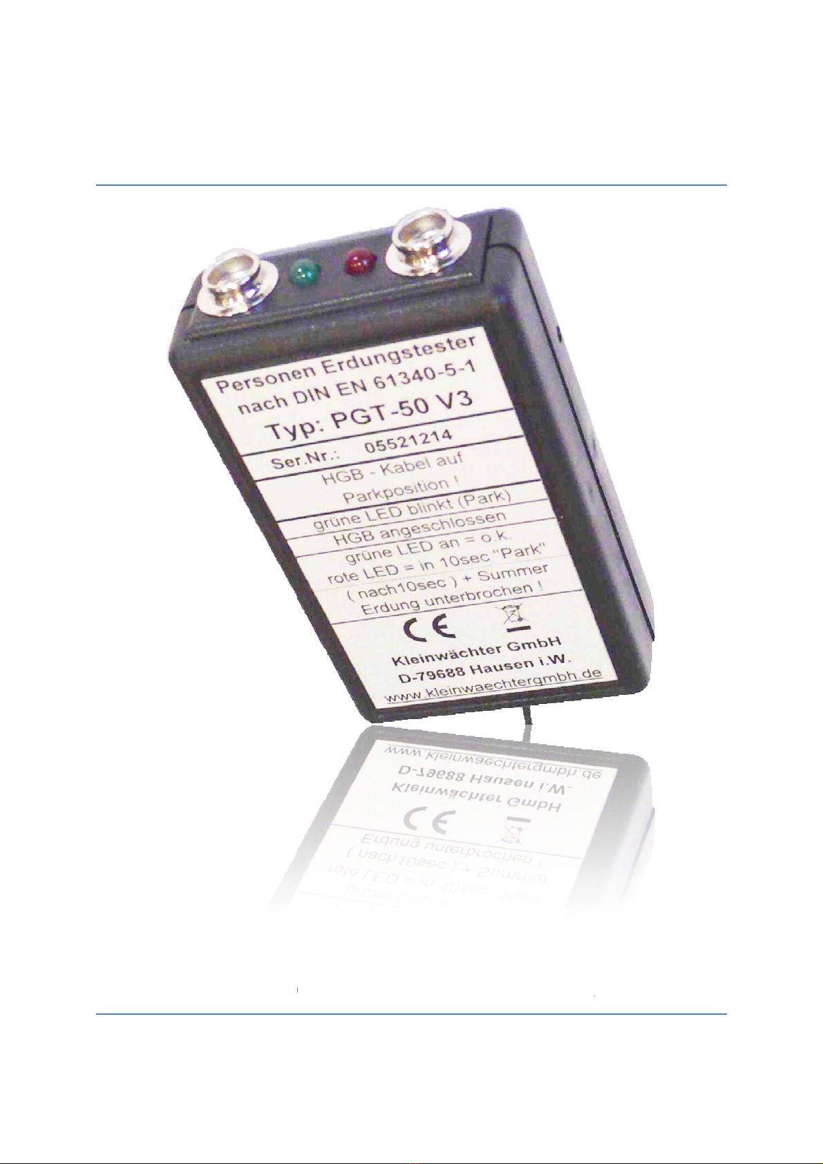
Description
The instrument is for permanent grounding monitoring of persons with wrist straps.
During this the capacitive resistance to earth is measured.
The unit is mounted on the workplace. The grounding must be connected to the grounding point
of the table or table mat. Only use included power supply plug.
Limits can be changed by user very easy. It can be done by calibrated resistors or by a reference
wrist strap.
By doing it with calibrated resistors it is an easy and cheap calibration of the unit.
The version PGT 52 also includes a potential free relay contact. This can be select as “o.k”. or
“Alarm” Output by jumper.
JUMPER
J M1 OFF (open) Calibrate limits by RRP-50 Calibration box
ON (closed) Calibration with reference wrist strap
Only PGT 52:
J M2 OFF (open) Relay Mode = Alarm (Relay turns on if not o.k.)
ON (closed) Relay Mode = o.k. (Relay turns on if o.k.)
J M3 OFF (open) delay time to turn on by Alarm mode 10 seconds
ON (closed) no delay time for relay