IMPORTANTE:
Pelo menos duas pessoas qualificadas devem executar o procedimento de montagem. Lesões
corporais e/ou danos à propriedade podem resultar de queda ou manuseio incorreto da tela.
Peso máximo do painel plano ou curvo: 50kg/110lb
A estrutura da parede deve ser capaz de suportar pelo menos cinco vezes o peso do painel.
Caso contrário, a estrutura da parede deve ser reforçada.
3. ATENÇÃO!
• Antes de instalar este produto, você deve ler todas as instruções cuidadosamente. Guarde
estas instruções de instalação em um local facilmente acessível para referência no futuro.
• Medidas de segurança devem ser praticadas durante todo o processo de montagem deste
produto. Use equipamentos e ferramentas de segurança adequados para o procedimento de
montagem para evitar ferimentos.
• A Klip Xtreme não cobre danos causados pelo uso de quaisquer suportes da Klip Xtreme
para outros fins que não aqueles para os quais foram projetados ou danos causados por
implementações ou modificações não autorizadas. E não é responsável por quaisquer danos,
reivindicações, demandas, ações, ações ou causas de ação de qualquer natureza resultantes,
ou de qualquer maneira relacionadas a qualquer uso, anexos ou modificações feitas.
Max load 50kg/110lb
50
kg
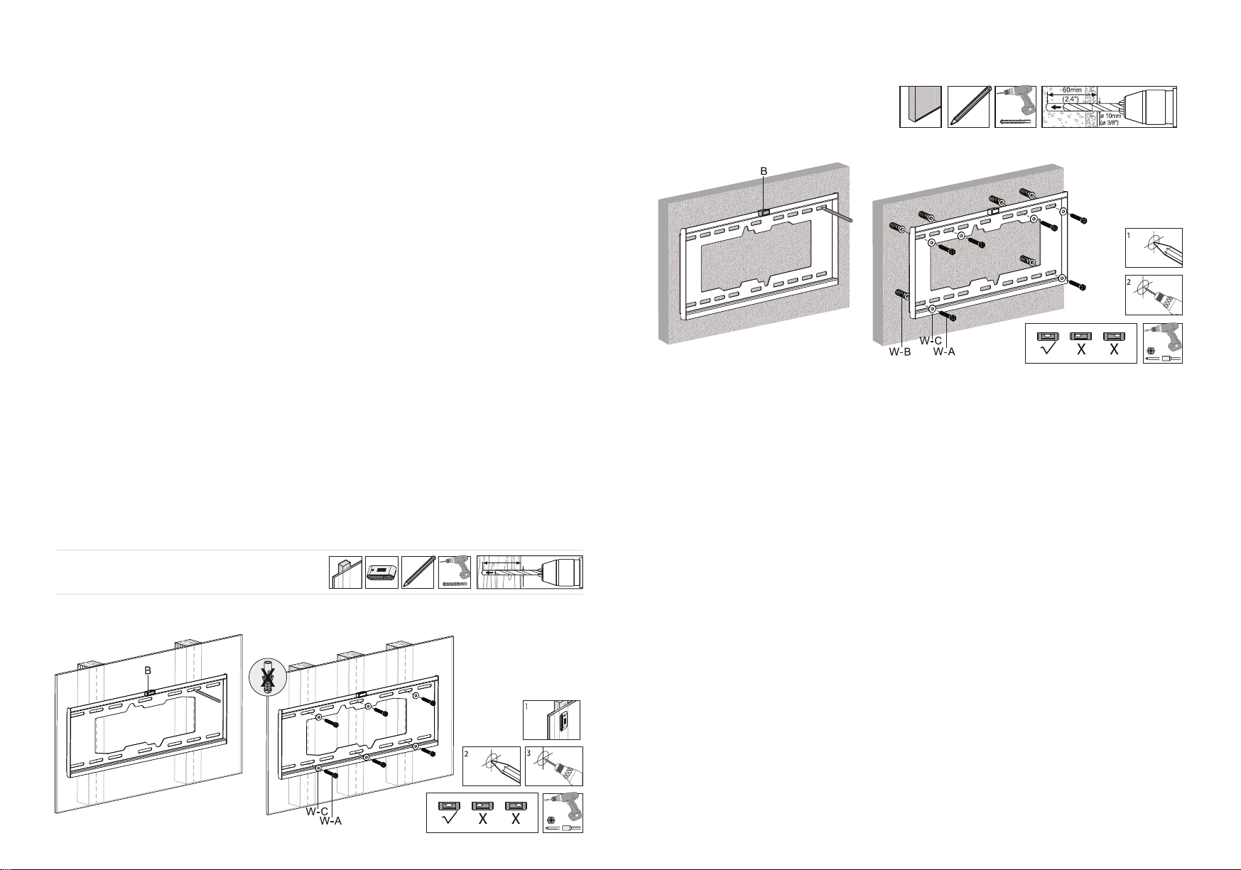
4. Instalação da placa de parede
1. Abra a embalagem e revise o conteúdo.
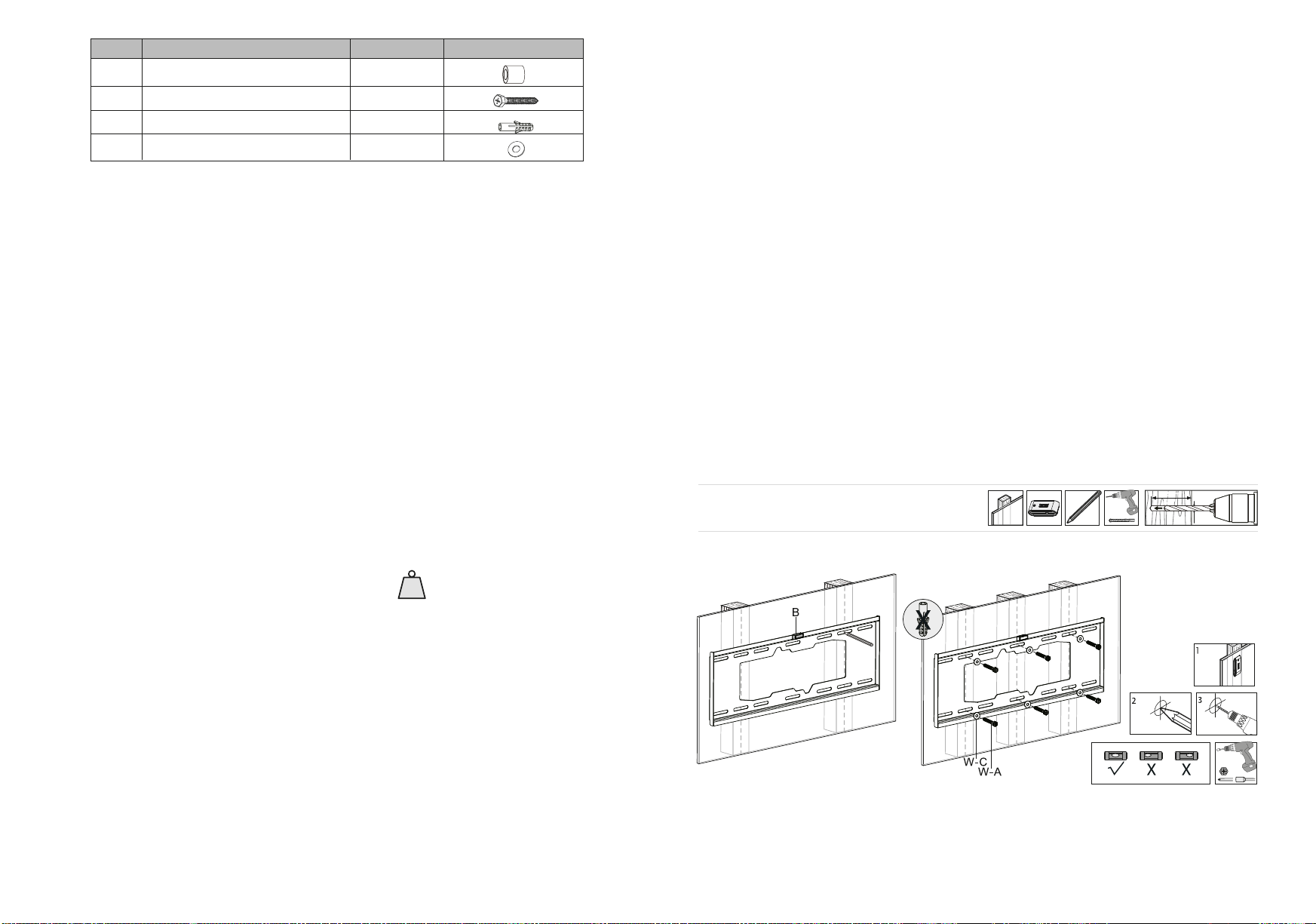
2. Primeiro localize as vigas na parede para uso em paredes de gesso ou madeira. Você pode
usar um localizador de vigas para determinar o centro de cada viga.
3. Usando a placa de parede como modelo, marque as seis posições de montagem, conforme
mostrado no desenho abaixo, com o nível de bolha determinar se eles estão nivelados em
relação ao solo. Verifique se os orifícios de montagem estão alinhados verticalmente e
centralizados na viga.
4. Antes de perfurar os orifícios de montagem na parede, posicione a placa de parede no lugar
e use o nível de bolha para verificar se está completamente horizontal, como mostra o
desenho. Caso contrário, tome as providências necessárias e prossiga para a próxima etapa.
5. Faça os furos piloto usando uma broca, conforme especificado no desenho. Para paredes de
concreto ou tijolo, insira as âncoras de concreto, certificando-se de que estão assentadas
alinhadas com a superfície.
6. Alinhe a placa de parede com os orifícios feitos na parede e segure-a no lugar.
7. Insira os parafusos de atraso e as arruelas e aperte-os firmemente.
8. Coloque o nível de bolha no centro do suporte de parede para verificar se a placa de
parede foi posicionada uniformemente na superfície.
Nota: a ferragem fornecida é compatível com padões VESA, correspondendo a todas as
especificações adotadas pelos fabricantes de telas e monitores de TV do setor mais conhecidos.
No entanto, certos dispositivos podem exigir tamanhos de parafusos diferentes e/ou arruelas
para conectar o painel traseiro ao suporte. Qualquer ferragem adicional necessário deve ser
fornecido separadamente pelo usuário.
2. Ferramentas necessárias para instalação
• Lápis
• Chave Phillips
• Localizador de vigas para instalação em paredes de gesso
• Broca elétrica e bit de alvenaria para instalação em concreto/tijolo (consulte o desenho para
obter o tamanho da broca).
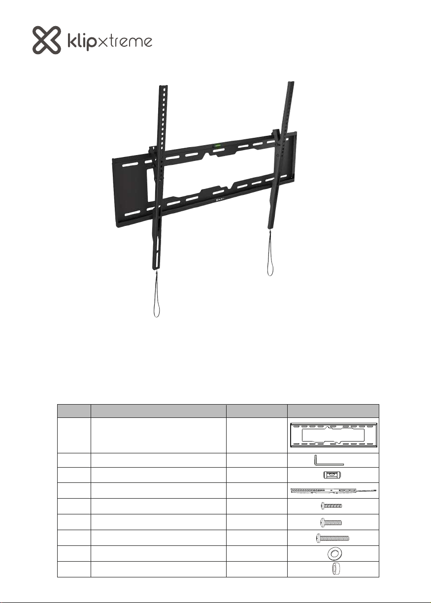
Etiqueta
M-F
W-A
W-B
W-C
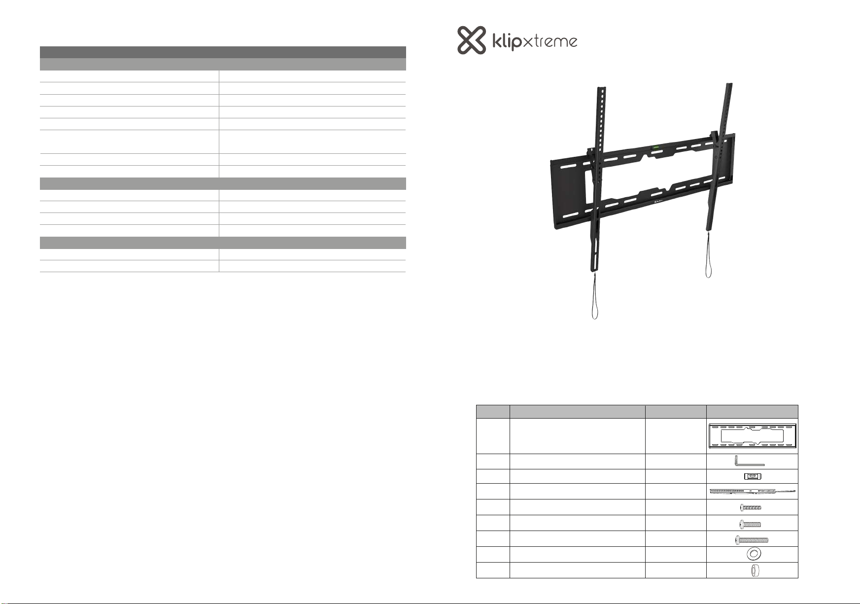
Item
Espaçador redondo longo
Parafuso de atraso
Âncora para concreto
Arruela plana de metal
Quantidade
8
6
6
6
Imagem
Instalação na superfície de madeira
55mm
(2.2")
ø 4.5mm
(ø 3/16 )"