KLJ Instruments SQTR-5 User manual

SQTR-5 UAT Ramp Test Set November 2011
2
NOTICE:
The information contained in this manual is subject to change without notice.
KLJ Instruments makes no warranty of any kind to this material, nor shall be liable including but not
limited to, errors contained herein or for incidental or consequential damages in connection with the
furnishings, performance, or use of this material.
COPYRIGHT NOTICE
© 2011 KLJ Instruments, Inc.

SQTR-5 UAT Ramp Test Set November 2011
3
Reproduction of this publication or any portion thereof by any means without the express written
permission of KLJ Instruments is prohibited.
Date
REV
ECO
Page
Description
Nov 2011
A
Initial Release

SQTR-5 UAT Ramp Test Set November 2011
4
INTRODUCTION
1.1 Manual Description
The SQTR-5 Ramp Test Set provides portable testing capability of Universal Access Transceiver (UAT) ADS-B
Squitters. The purpose of this manual is to provide instructions for use of the SQTR-5. The SQTR-5 is housed in a
rugged case and is supplied with a tablet computer (stored in case lid) for control of the SQTR-5 via a Wi-Fi connection.
The SQTR-5 is supplied with an RF antenna for over-the-air testing of the UAT transceiver that is mounted on the case
lid and connected to SUM antenna connection. The SQTR-5 antenna connection is designed to be used with a variety
of optional antennas which may be connected to the SQTR-5 using the SUM and DIFF (Difference) connections. A
GPS connection is for future application that may require a GPS antenna. A Wi-Fi wireless antenna is supplied with the
SQTR-5 and should be connected to the front-panel WIRELESS connection. Front-panel BNC connectors allow
connection of an oscilloscope for monitoring of various signals: RECEIVER (FSK allows viewing of demodulated signal
coming from UAT and VIDEO allows viewing of UAT data pulse or Mode S reply), UAT TRANSMITTER (Scope sync
provides pulse relative to the first pulse of the UAT signal being transmitted by the SQTR-5 and the VIDEO allows
viewing of the SQTR-5 transmitted pulse), and MODE S TRANSMITTER (Scope sync provides pulse relative to the first
pulse of the Mode S interrogation and the VIDEO allows viewing of the Mode S data pulse).
1.2 Front Panel Description
SQTR-3BB Front Panel
1
Battery Status
LED indicates status of battery (refer to table next to LED)
2
Battery Charging Switch
Switch to turn battery charging circuit ON (1) or OFF (0)
3
ON/OFF Power Switch
Turns test set ON or OFF
4
Ethernet Connector
Used for connection of Ethernet cable
5
Wi-Fi Wireless Antenna
Used for connection of Wi-Fi antenna
6
Receiver
Detected FSK waveform, UAT or Mode S signal, and LEDs indicating signal activity
7
UAT Transmitter
Scope sync and video display of test set transmitted signal and LED indicating TX activity
8
Mode S Transmitter
Scope sync and video display of test set transmitted signal and LED indicating TX activity
9
GPS Antenna
Provides connection for GPS antenna (possible future application - not required at this time)
10
RF Antenna
Provides connection for variety of RF antennas for TX/RX of signals to/from unit being tested
1
2
3
4
5
6
7
8
9
10

SQTR-5 UAT Ramp Test Set November 2011
5
1.3 SQTR-5 Function
The SQTR-3BB provides capability for generating the following test functions:
Transmits Mode S 1030 interrogation (UF4 format) to get altitude information contained in the transponder Mode S
1090 reply (DF4)
Transmits UAT 978 MHz ADS-B squitter for simulation of a single, UAT target that is used to test the UAT receiver
and aircraft UAT display system
Receives UAT ADS-B squitter from the aircraft being tested, decodes the signal, and displays data being received
from the UAT transmitter
The SQTR-5 Test Set is controlled via a tablet computer supplied with the test set that communicates via a wireless
(Wi-Fi) connection or through a wired network via an Ethernet cable. Selection between wireless or wired connection is
done automatically depending on whether the user uses an Ethernet cable or not.
The SQTR-5 and tablet are battery powered and should operate about 2 hours on a fully charged battery. Power cables
are provided for charging batteries.
1.4 Initial Setup
To test a UAT transceiver in an aircraft, open the SQTR-5 case and remove the tablet computer from the case lid.
Connect the RF antenna (mounted on case lid) to the front-panel Antenna SUM connection. Turn the open case of the
SQTR-5 so that the lid of the case has a direct, line-of-sight to the UAT and Mode S transponder antennas. Turn on the
SQTR-5 first and then turn on power to the table computer (the power switch is located on the upper edge of the tablet
computer as you face it. The tablet computer uses a Windows operating system and will "boot" up automatically into
the SQTR-5 program. The tablet computer can be rotated
for use in either landscape or portrait mode.
1.5 Wireless Connection
The SQTR-5 will automatically connect to the tablet
computer through Wi-Fi. If the SQTR-5 is turned on first,
the tablet computer may take up to 60 seconds to
establish connection. If the tablet is turned on before the
SQTR-5, it may take a couple of minutes to establish a
wireless connection. While the tablet computer is
attempting to make connection with the SQTR-5, you will
see the message NO ACTIVE WIRELESS CONNECTION
(MAY TAKE 60 SECONDS) shown with a red background.
RF Antenna mounted on lid --
Antenna Cable stored in lid
Remove RF Antenna Cable from lid
and connect to SUM connector

SQTR-5 UAT Ramp Test Set November 2011
6
When the Wi-Fi wireless connection is completed,
the MAIN SCREEN will show WIRELESS
CONNECTION OPERATIONAL at the top of the
screen and the READY TO RUN message will be
shown.
Prior to testing, press the SETUP key in the upper
left-hand corner to access the Setup screen.
1.6 Setup Screen
The Setup Screen is used to set the Aircraft Data for the aircraft being tested, Traffic Data for the UAT target that will be
transmitted, and Test Data for setup of the SQTR-5. A keypad will be displayed when one of the fields to be set (e.g.
Address) is "touched".
The ICAO Mode S Address (24-bit) of the aircraft being tested is displayed in hexadecimal. To change the address,
touch the address field and the keypad will appear if not already displayed. The Address will appear with a "|" at the
end of the address on the keypad. Use the backspace (bksp) key to select the part of the address that needs to be
changed using the keypad. Press the "enter" key when completed.
The GPS Latitude and Longitude are displayed in DEG:MIN:SEC by placing a "√" in the USE DDMMSS FOR
DEGREES or in decimal by removing the "√". To change the Latitude or Longitude, touch the field to be changed. For
Latitude, a "|" will appear at the end of the data. Use the backspace key to select the data to be changed using the
keypad. You must add spaces between DEG, MIN, and SEC plus press the North and South (N/S) key. Press the
"enter" key when completed.
The Altitude for the aircraft being tested should be set to standard pressure altitude. The Altitude can be determined by
setting the aircraft altimeter setting to 29.92 in Hg. and reading the aircraft altitude on the altimeter.

SQTR-5 UAT Ramp Test Set November 2011
7
All other fields can be changed the same as Address and Latitude as described above. When all Setup fields are
correct, press the SAVE key to return to the Main Menu.
Checking the ENABLE MORE DETAILS box controls the amount of data shown in the MAIN SCREEN. To view the
additional data on the MAIN SCREEN, touch the SUMMARY DATA column.
1.7 Main Screen
After setup is completed, the screen shown
to the right will appear if the ENABLE
MORE DETAILS box was not checked. A
READY TO RUN message should appear
at the top of the screen. Press RUN to
begin testing.
After RUN is pressed, the test set will
interrogate the aircraft Mode S
transponder with a UF4 interrogation in
order to obtain the aircraft altitude. If a
DF4 reply is received from the Mode S
transponder, the altitude will be
displayed. If the SQTR-5 does not
receive the Mode S reply with Altitude
within 30 seconds, it will advance to the
UAT tests. When Mode S is not
received, the Altitude Mode S display will
have a yellow background. During the
UAT test, the MODE S TRANSMITTER
1030 INTR LED will flash at each Mode S
interrogation and the RECEIVER MODE
S LED will flash at each Mode S reply
and squitter.

SQTR-5 UAT Ramp Test Set November 2011
8
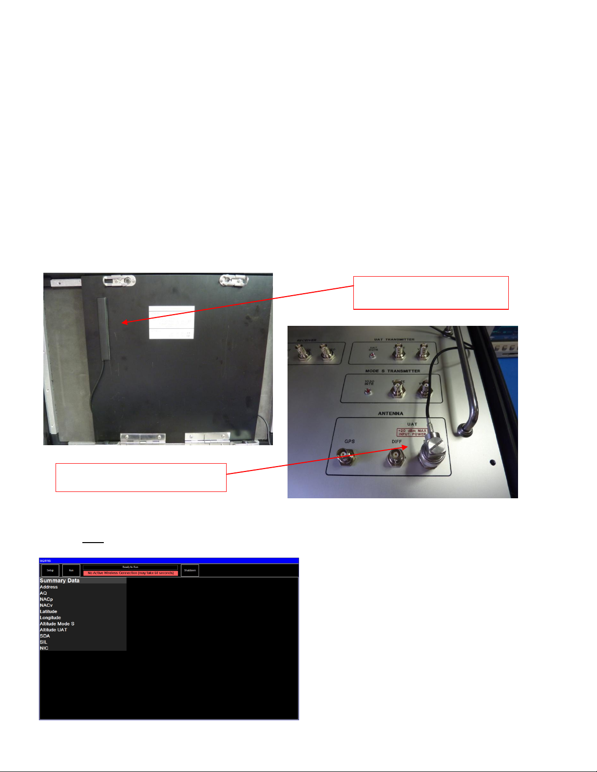
Next, the SQTR-5 will begin to receive the
UAT data or Payload Data from the UAT being
tested. The SUMMARY DATA Screen will
display the data that is required to be tested to
determine if the UAT is transmitting the proper
data. The test set will validate UAT Address,
Latitude/Longitude, and Altitude values. When
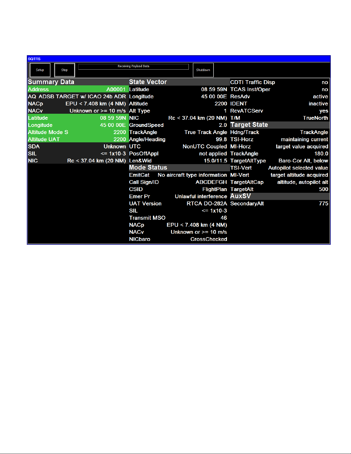
not all data is available for Address, Latitude
and Longitude, and Altitude, the background
color will be black. When data exists to
perform a validation, valid data will use a green
background and a red background when not
valid.
The Mode S Address being transmitted by the
UAT will be displayed with a green background
if it agrees with the Mode S Address that was
entered in the Setup Screen. If the Address
does not agree with the Address entered in the
Setup Screen, the Address will be shown with
a red background.
The Latitude and Longitude being transmitted
by the UAT will be displayed with a green
background if the distance between the UAT
Latitude and Longitude and the Latitude and
Longitude entered in the Setup Screen is
computed to be within the specified NACp
value. If not correct, the Latitude and Longitude will be displayed with a red background.
The Altitude being transmitted by the UAT and the Altitude obtained from the Mode S transponder will be displayed. If
the UAT and transponder altitudes agree within + 75 ft and the UAT Altitude agrees within + 125 ft of the value entered
in the Setup Screen, the Altitude fields will be displayed with green background if the Altitude requirement is met or red
background if they do not meet the requirement.
Aircraft UAT system data will be displayed including: Navigation Accuracy Category for Position (NACp), Navigation
Accuracy Category for Velocity (NACv), System Design Assurance (SDA), Source Integrity Level (SIL), and Navigation
Integrity Category (NIC).

SQTR-5 UAT Ramp Test Set November 2011
9
1.8 Main Screen (More Details)
If the MORE DETAILS box was checked in the Setup Screen and then touch the column that contains SUMMARY
DATA, additional UAT data will be received and displayed including STATE VECTOR, MODE STATUS, TARGET
STATE, and AUXILIARY STATE VECTOR. Please note that some of these fields may not be displayed as that data is
dependent on the configuration of the aircraft (e.g. aircraft on ground or in the air). Consult your UAT maintenance
manual for further information.
1.9 Shutdown
When testing is complete, press the SHUTDOWN button to turn off the tablet computer and then turn off the SQTR-5
using the ON/OFF Power Switch.
This manual suits for next models
1
Table of contents
Popular Test Equipment manuals by other brands

BACtrack
BACtrack BREATH ALCOHOL DETECTOR owner's manual

G.R.A.S.
G.R.A.S. 42AC instruction manual

Keysight Technologies
Keysight Technologies S8780A Getting started guide

Huazheng
Huazheng HZJB-D manual

Spinner
Spinner SmartLoad 25 kW product manual

Lutron Electronics
Lutron Electronics DL-9954 Operation manual