6 GOSSEN-METRAWATT
1 Safety Features and Precautions
The tester is manufactured and tested in accordance with the following standards:
IEC/EN 61010-1/
VDE 0411-1 Safety regulations for electrical measuring, control,
regulating and laboratory devices – general requirements
and DIN VDE 0404 Devices for the technical safety inspection of electrical equipment;
Part 1: general requirements, and Part 2:
periodic device testing
When used for its intended purpose, the safety of the user, the test instrument and the device
under test (electrical equipment) is assured.
Read the operating instructions carefully and completely before placing your test instrument into ser-
vice, and follow all instructions contained therein. Make sure that the operating instructions are avail-
able to all users of the instrument.
The tests may only be conducted under the supervision of a qualified electrician. The user must be in-
structed by a qualified electrician in the perfomance and evaluation of the test.
Observe the following safety precautions:
• The device may only be connected to a mains outlet rated at 230 V which is protected
with a fuse or circuit breaker rated at max. 16A.
• No measurements within electrical systems are allowed.
• Be prepared for the occurrence of unexpected voltages at devices under test. For exam-
ple, capacitors may be dangerously charged.
• Make certain that connector cables are not damaged, e.g. damaged insulation, interrup-
tions etc.
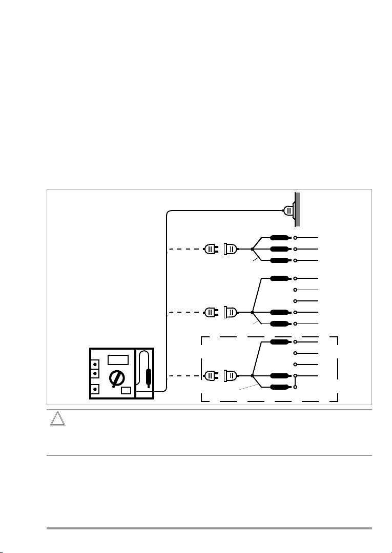
Attention!
!
Devices under test may only be connected to the mains outlet after they have
successfully completed safety testing in accordance with DIN VDE 0701 or
DIN VDE 702!
Repair, Parts Replacement and Balancing
Voltage conducting parts may be exposed when the device is opened. The device must be
disconnected from all sources of voltage before repair, replacement of parts or balancing. If
repair or balancing of an open, live device cannot be avoided, this may only be performed by
trained personnel who are familiar with the dangers involved.
Errors and Extraordinary Strains
If it may be assumed that the device can no longer be operated safely, it must be removed
from service and secured against unintentional use. Safe use can no longer be relied upon,
• if the device demonstrates visible damage,
• if the device no longer functions,
• after lengthy periods of storage under unfavorable conditions,
• after excessive, transport related strains.
Approvals
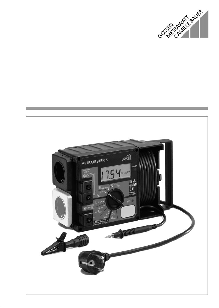
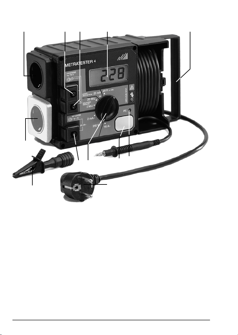
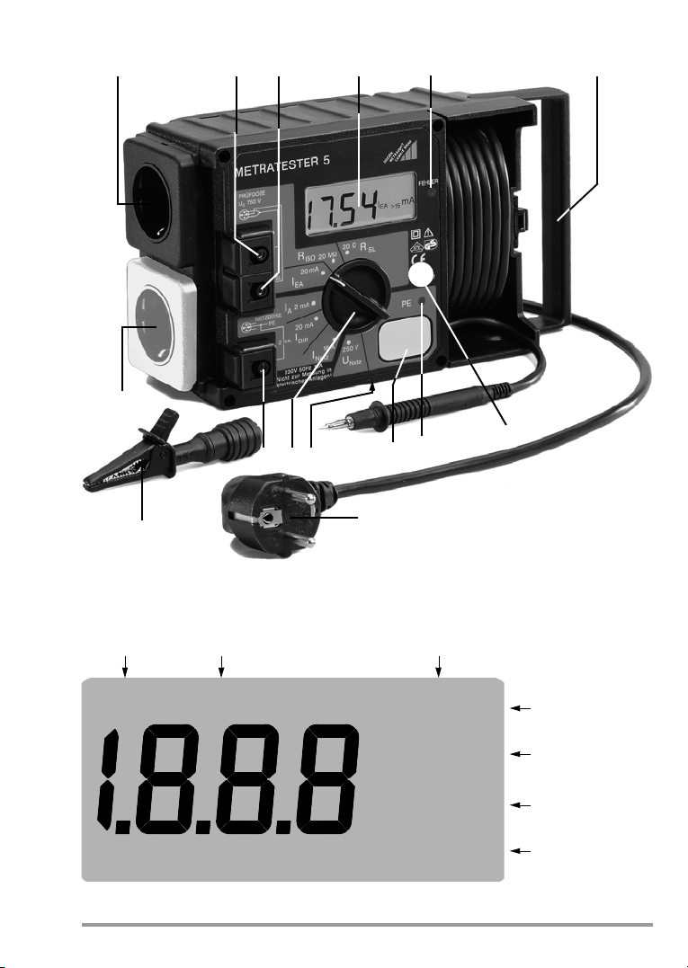
Branding of the METRATESTERâ4 and 5 testers with the VDE GS mark
has been approved by VDE testing authorities.