Stahlwille perfectControl 7794-2 User manual

English version of original German operating
instructions
EN
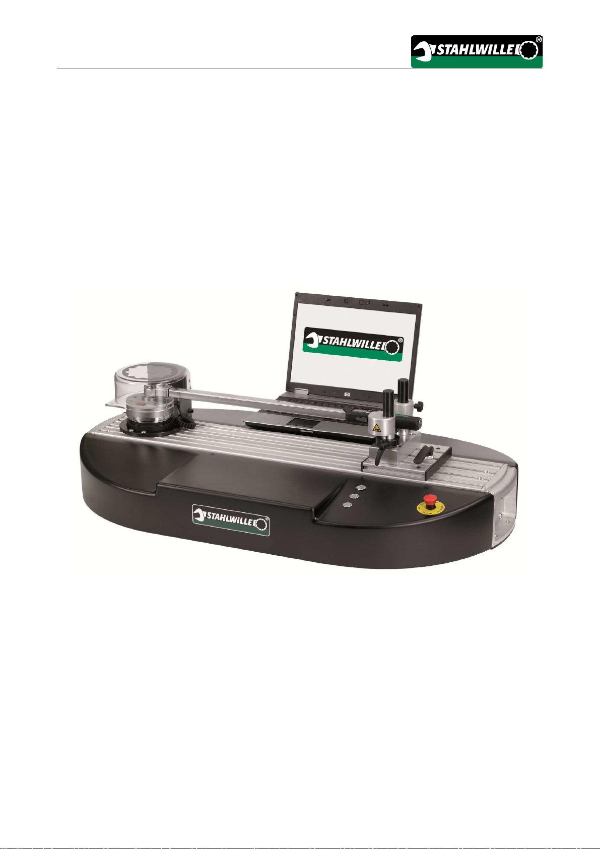
STAHLWILLE perfectControl
Motor-operated calibration and adjustment facility 7794-2
Read through these operating instructions carefully to ensure safe operation. Store these
instructions for further use.
Code number 91979873
Status: 06/2016

Preface
2
Preface
These operating instructions help you to make
•proper,
•safe and
•economical
use of the motor-operated calibration and
adjustment facility.
Target group of these operating
instructions
The operating instructions are aimed at the users of
the motor-operated calibration and adjustment
facility.
The information contained in these operating
instructions is aimed at authorised, trained and
familiarised personnel. We assume that these
persons possess general technical knowledge.
Each person who
•transports
•installs,
•dismantles,
•operates,
•maintains or
•disposes of
the adjustment and calibration facility must have
read and understood the corresponding contents of
these operating instructions.
If you do not understand any of the information in
these operating instructions or information is
missing, please contact
STAHLWILLE Eduard Wille GmbH & Co. KG.

Contents
Preface ........................................................................................................................................................ 2
Target group of these operating instructions ...................................................................................................... 2
Introduction to the operating instructions ................................................................................................. 6
Availability ........................................................................................................................................................... 6
Supplements ....................................................................................................................................................... 6
Structural features .............................................................................................................................................. 6
Explanation of the warning notices ..................................................................................................................... 6
Safety .......................................................................................................................................................... 7
Proper use, operating area ................................................................................................................................. 7
Basic safety instructions ..................................................................................................................................... 7
Dangers due to electrical energy .............................................................................................................. 7
Risk of injury due to damaged calibration objects .................................................................................... 7
Risk of injury due to crushing ................................................................................................................... 8
Hazards due to noise ............................................................................................................................... 8
Environmental pollution due to incorrect disposal .................................................................................... 8
Avoiding material damage .................................................................................................................................. 8
Warranty and liability .......................................................................................................................................... 8
Changes to the design of the calibration and adjustment facility ....................................................................... 8
Duties when handling this calibration and adjustment facility ............................................................................ 9
Obligations on the part of the owner ........................................................................................................ 9
Obligations on the part of the personnel .................................................................................................. 9
Personnel training ............................................................................................................................................... 9
Safety equipment ................................................................................................................................................ 9
Safety measures during normal operation.......................................................................................................... 9
Protective facilities ............................................................................................................................................ 10
Emergency stop button .......................................................................................................................... 10
Protective cover ...................................................................................................................................... 10
Edge guard on the longitudinally adjustable carriage ............................................................................ 10
Limitation of the movement range .......................................................................................................... 11
Motor overload protection ....................................................................................................................... 11
Transducer overload............................................................................................................................... 11
Calibration object overload ..................................................................................................................... 11
Warning and instruction signs .......................................................................................................................... 11
Technical description ............................................................................................................................... 12
Overview ........................................................................................................................................................... 12
Technical data .................................................................................................................................................. 13
Electrical protection .......................................................................................................................................... 14
Identification ...................................................................................................................................................... 14
Transportation, delivery, storage ............................................................................................................. 14

Transportation ................................................................................................................................................... 14
Unpacking ......................................................................................................................................................... 15
Delivery ............................................................................................................................................................. 16
Scope of delivery .................................................................................................................................... 16
Check on acceptance by the recipient ................................................................................................... 16
Reporting and documenting transport damage ...................................................................................... 16
Packaging ............................................................................................................................................... 17
Storage ............................................................................................................................................................. 17
Erection and mounting ............................................................................................................................. 18
Installing extension 7791-1 ....................................................................................................................... 18
Connecting ................................................................................................................................................ 21
Characteristic electrical data of the control system .......................................................................................... 21
Overview of external connections ..................................................................................................................... 21
Establishing connections .................................................................................................................................. 22
Operating the calibration and adjustment facility ................................................................................... 23
Controls............................................................................................................................................................. 23
Control functions ............................................................................................................................................... 24
Using the TORKMASTER 4 programme ................................................................................................... 25
Installing the software ....................................................................................................................................... 25
Installing the TORKMASTER 4 programme ........................................................................................... 25
Manually installing the driver .................................................................................................................. 27
The main menu controls ................................................................................................................................... 28
Operating the TORKMASTER 4 programme ................................................................................................... 31
Preparing for operation ............................................................................................................................ 32
Preparing the calibration and adjustment facility .............................................................................................. 32
Preparing the PC .............................................................................................................................................. 32
Calibrating and adjusting torque wrenches ............................................................................................ 33
Starting the calibration and adjustment facility ................................................................................................. 33
Set-up mode ..................................................................................................................................................... 33
Testing and adjusting ........................................................................................................................................ 34
Clicking calibration ............................................................................................................................................ 34
Measuring calibration ........................................................................................................................................ 35
Maintenance .............................................................................................................................................. 36
Cleaning ............................................................................................................................................................ 36
Exchanging fuses ............................................................................................................................................. 36
Lubricating ........................................................................................................................................................ 37
Maintenance schedule for the mechanical system ........................................................................................... 38

Disposal .................................................................................................................................................... 39
Information on extension lengths ............................................................................................................ 39
The correct tightening torque with unchanged extension lengths .................................................................... 39
The correct tightening torque with changed extension lengths ........................................................................ 39
Example 1: corrected setting value (one plug-in tool) ............................................................................ 40
Example 2: corrected setting value (plug-in tool and adapter) ............................................................... 41
General information on calibration .......................................................................................................... 42
Torque wrench dimension tables ............................................................................................................. 43
Subsequent additions to the operating instructions ............................................................................... 47
EU declaration of conformity ................................................................................................................... 48

Introduction to the operating instructions
6
Introduction to the operating
instructions
Availability
A complete and legible copy of the operating
instructions must always be stored at the calibration
and adjustment facility's operating location.
If these operating instructions become lost or
unusable, a new copy can be requested from
STAHLWILLE Eduard Wille GmbH & Co. KG.
If you have not yet registered the device, the
following data are required for reordering:
•Serial number of your calibration and adjustment
facility
•Name of your dealer
•The code number of the operating instructions
can be found at the bottom left of the title page.
In addition to the operating instructions, the
generally applicable and local accident prevention
and environmental protection regulations must be
made available and observed.
Keep all safety notices and information on dangers
on the calibration and adjustment facility in legible
condition.
Supplements
Regularly add instructions to the operating
instructions at the relevant operating location due to
•Legal regulations concerning accident prevention,
•Legal regulations concerning environmental
protection and
•Trade association stipulations.
Structural features
Defined structural features are assigned to the
various elements within the operating instructions.
You can therefore easily determine the type of text
which this involves:
Normal text,
•Lists or
Action steps.
Notices with this symbol contain general
information and information regarding the
economical use of the testing facility.
Explanation of the warning notices
The following categories of notices are contained in
these operating instructions:
DANGER
Notices containing the word DANGER
warn of hazards which lead directly to
severe or fatal injuries.
WARNING
Notices containing the word
WARNING warn of hazards which may
possibly lead to severe or fatal injuries.
CAUTION
Notices containing the word CAUTION
warn of hazards which may possibly
lead to minor to moderate injuries.
ATTENTION
Notices containing the word
ATTENTION warn of hazards in which
property damage may possibly occur.

Safety
7
Safety
Proper use, operating area
The machine is exclusively intended to be used in
adjusting and calibrating torque wrenches and
STAHLWILLE transducers within the framework of
the technical specifications.
Proper use additionally includes:
•Compliance with all notes contained in the
operating instructions
•Observance of all instruction signs on the
machine
•Adherence to the inspection and maintenance
intervals.
Any other use is regarded as improper, particularly
bending objects.
STAHLWILLE Eduard Wille GMBH & CO. KG
accepts no liability for damage arising as a result of
this.
Basic safety instructions
Dangers due to electrical energy
There is a risk of fatal accident due to electric shock
if you ignore the following safety instructions.
•Never open the housing of the calibration and
adjustment facility.
•Only connect the calibration and adjustment
facility to a properly installed mains socket of 100-
240 V ~, 50/60 Hz.
•The mains plug must be freely accessible so that
the calibration and adjustment facility can be
easily and quickly disconnected from the mains
power supply in an emergency.
•Disconnect the calibration and adjustment facility
from the mains power supply in the following
cases:
−Before cleaning,
−When installing accessories,
−In the event of mechanical damage,
−When the calibration and adjustment facility is
not used for a long period of time.
•Switch the calibration and adjustment facility off at
the mains switch on the rear or remove the mains
plug from the socket. Pull only on the mains plug
in this case.
•The calibration and adjustment facility and the
mains power cable must not be exposed to water.
•Do not place any objects filled with fluids on, next
to or above the calibration and adjustment facility.
•Do not install the calibration and adjustment
facility in the vicinity of water.
•Do not touch the mains power cable or the
calibration and adjustment facility with moist
hands.
•Do not kink or crush the mains cable.
•Never use the calibration and adjustment facility
with a damaged mains power cable, following a
malfunction or when the calibration and
adjustment facility is damaged. Have the
calibration and adjustment facility checked or
repaired by the service department before using it
again.
•Always have repair or maintenance work carried
out by qualified, specialist personnel.
Risk of injury due to damaged calibration objects
•Under certain circumstances, parts may break or
fracture when loading damaged calibration
objects.
Check calibration objects and insertion tools for
damage (cracks or fractures) before calibrating.
Do not calibrate damaged calibration objects or
insertion tools.
•To avoid risks of injury due to the calibration
object or the square adapter splintering, always
operate the calibration and adjustment facility with
the protective cover mounted.

Safety
8
Risk of injury due to crushing
When operating the calibration and adjustment
facility, there is a risk of crushing the fingers at the
following points:
•Between the supporting bolts and the calibration
object
•On the longitudinally adjustable carriage between
the carriage and the transducer bracket
Hazards due to noise
•Depending on the calibration object, a sound
pressure level (torque wrench triggering impact)
which causes deafness may occur.
Wear ear protectors in these cases.
Environmental pollution due to incorrect disposal
•Dispose of cleaning agents and lubricants
according to the regulations applicable at the
operating location.
•Dispose of the calibration and adjustment facility
according to the regulations applicable at the
operating location.
Avoiding material damage
Avoid material damage on the device and the
torque wrenches through the following measures:
•Make sure that the torque wrenches are not
damaged.
•Only insert the torque wrenches in the manner
described in these operating instructions.
Warranty and liability
Warranty and liability claims in the event of personal
injury and material damage are inadmissible if they
are attributable to one or more of the following
causes:
•Improper use of the calibration and adjustment
facility.
•Improper installation, commissioning, operation
and maintenance of the calibration and
adjustment facility.
•Operation of the calibration and adjustment facility
with defective safety facilities or improperly
installed or non-functional safety and protective
devices.
•Non-observance of the notes in the operating
instructions.
•Unauthorised modification of the calibration and
adjustment facility's characteristics.
•Inadequate monitoring of parts of the calibration
and adjustment facility which are subject to wear.
•Improperly carried out repairs.
•Disasters due to the effect of foreign bodies and
acts of God.
•Non-observance of the requirements contained in
the relevant standard during calibration.
•Non-observance of the manufacturer's
instructions on calibrating and adjusting
calibration objects.
Changes to the design of the calibration
and adjustment facility
•Do not carry out any modifications, attachments
or conversions on the calibration and adjustment
facility without the approval of the manufacturer.
•Immediately exchange parts of the machine which
are not in flawless condition.
•Use only genuine replacement and wearing parts.
Parts procured from third-party manufacturers
provide no guarantee of the fact that they have
been designed and manufactured to cope with the
stress and function safely.

Safety
9
Duties when handling this calibration
and adjustment facility
Obligations on the part of the owner
The owner is obliged only to allow the following
persons to work on the calibration and adjustment
facility:
•Persons who are familiar with the basic
regulations concerning industrial safety and
accident prevention, and who have been trained
in handling the calibration and adjustment facility,
•Persons who have read and understood the
chapter on safety and the warning notices
contained in the operating instructions, and have
confirmed this with their signature,
•Persons who are familiar with and have
understood the requirements for calibrating torque
wrenches.
Responsibility for the properly executed calibration
and adjustment of torque wrenches is borne by the
owner or user.
Obligations on the part of the personnel
Before starting work, all persons commissioned to
carry out work on the calibration and adjustment
facility must be obliged:
•To observe the basic regulations concerning
industrial safety and accident prevention,
•To read the chapter on safety and the warning
notices contained in the operating instructions,
and to confirm with their signature that they have
read and understood these,
•To comply with the requirements of the relevant
standard on calibration.
Personnel training
•Only trained and familiarised personnel may work
on the calibration and adjustment facility.
•The user's qualification requirements must be
defined by the customer. We recommend basic
technical training with advanced quality assistant
training.
•The personnel's responsibilities must be clearly
defined for installation, commissioning, operation,
set-up and maintenance work.
•Personnel undergoing on-the-job training may
only work on the calibration and adjustment
facility under the supervision of an experienced
person.
•The personnel must be familiar with the
application and handling of calibration objects.
•The personnel must have detailed knowledge of
EN ISO 6789 and standards or works'
requirements to be applied by the user.
•The personnel must have knowledge of the
operation of a PC and the software installed on it.
Safety equipment
•The required personal safety equipment must be
provided by the owner.
Safety measures during normal
operation
•Only operate the calibration and adjustment
facility if all protective facilities are fully functional.
•Before switching on the calibration and
adjustment facility, make sure that nobody can be
endangered by the calibration and adjustment
facility starting.
•At least once per shift, check the calibration and
adjustment facility for externally visible damage
and to ensure that the protective facilities are
functional.

Safety
10
Protective facilities
The calibration and adjustment facility is equipped
with various protective facilities.
Regularly check all available protective facilities as
per the maintenance schedule.
•In the event of an emergency, the calibration and
adjustment facility is shut-down using an
emergency stop button.
•Each time before the calibration and adjustment
facility is started up, all protective facilities must
be installed properly and within easy access, and
must be functional.
•Protective facilities must not be manipulated.
Emergency stop button
The calibration and adjustment facility is equipped
with an emergency stop button. A further
emergency stop button is available on the manual
operating terminal which can additionally be
connected.
Motor operation is stopped after pressing the
emergency stop button. An ongoing adjustment or
calibration process is cancelled.
Proceed as follows after pressing the emergency
stop button:
Eradicate the cause of the malfunction.
Make sure that the calibration and adjustment
facility is in flawless condition.
Release the emergency stop button by turning it
clockwise to stop.
Acknowledge the fault with the tare/reset button.
Protective cover
A protective cover is mounted above the
transducer. In the event of a defect on the square
adapter or the insertion tool, this protective cover
prevents splintering parts from causing injury.
The position of the protective hood is polled using a
safety switch. If the protective cover is opened
during operation, this leads to immediate
cancellation of the calibration process. It is not
possible to start up the calibration and adjustment
facility when the protective cover is open. No
loading or rotation can be carried out.
Keep the protective cover clean. When closing the
protective cover, no foreign objects must be present
between the protective cover and the calibration
object.
Edge guard on the longitudinally adjustable carriage
To prevent cutting or trapping the fingers when
adjusting the longitudinally adjustable carriage, it
must be fitted with edge guards (1).

Safety
11
Limitation of the movement range
Limit switches are located in the calibration and
adjustment facility's drive system. The limit switches
limit the movement range. If the permissible
movement range is exceeded and a limit switch is
actuated as a result, the calibration process is
cancelled. During set-up mode, the calibration and
adjustment facility can be manually moved outside
of this range. Exceeding the permissible movement
range may be caused for example by an improperly
adjusted ratchet on a torque wrench.
Motor overload protection
The motor is equipped with an overload and
temperature protection facility. If this is triggered,
the calibration process is cancelled.
Proceed as follows in this case:
Switch the calibration and adjustment facility off
and allow the motor to cool down.
Switch the calibration and adjustment facility on
again after it has cooled.
Transducer overload
During operation, the calibration and adjustment
facility constantly checks the transducer, which
serves as a reference, for overloading. The
transducer may be overloaded by a maximum of
25 % of the maximum measuring range value. The
software reports possible overloading via a warning
prior to the start of a calibration process. If
overloading occurs, the calibration process is
cancelled.
Calibration object overload
During operation, the calibration and adjustment
facility constantly checks the calibration object for
overloading. The calibration object may be
overloaded by a maximum of 20 % of the maximum
measuring range value. If overloading occurs, the
calibration process is cancelled.
Warning and instruction signs
Observe and comply with the warning and
instruction signs mounted on the device.
Make sure that none of the warning and
instruction signs mounted on the device are
covered over and that they are all clearly legible
at all times.
Immediately replace damaged warning and
instruction signs.

Technical description
12
Technical description
Overview
1 2 3 4
5
67
8
No. Explanation
1 Protective cover
2 Bridge anti-trapping guard
3 Vertically adjustable rest for the
calibration object
4 Longitudinally adjustable carriage
No. Explanation
5 Handle
6 Emergency stop button
7 Buttons
8 Transducer flange

Technical
description
13
Technical data
Max. permissible relative humidity 70 % (non-condensing)
Ambient temperature in the laboratory From 18 °C to 28 °C (in accordance with EN ISO 6789:2003)
IP system of protection IP 20
Operating temperature range From 10 °C to 40 °C
Connection voltage 100 to 240 V AC
Frequency 50 to 60 Hz
Total output 250 W
Electrical fuse 2 x 6.3 A glass tube fuse T6.3A/250 V (at the IEC power
connector socket)
No. of phases 1-phase
Dimensions (L x W x H) approx. 1060 x 640 x 330 mm
Weight 50 kg

Transportation, delivery, storage
14
Electrical protection
The calibration and adjustment facility is equipped
with one IEC power connector socket. This is fused
with two thermal glass fuses 6.3 A. If these fuses
trip due to overload, the control circuit for the entire
calibration and adjustment facility is switched off.
Identification
The calibration and adjustment facilities can be
identified via a serial number. The type plate is
mounted next to the electrical connections on the
calibration and adjustment facility.
Type of product Motor-operated calibration and adjustment facility
Type 7794-2
Intended use Calibration and adjustment
Date of production Month and year: See type plate
Transportation, delivery,
storage
Transportation
Comply with the following safety instructions when
transporting the calibration and adjustment facility:
DANGER
Life-threatening injuries due to falling
or tipping calibration and adjustment
facility
Make sure that the aids for
transporting the machine parts are
undamaged and have the required
carrying capacity.
CAUTION
Risk of injury when carried by one
person.
Only raise the calibration and
adjustment facility using suitable
lifting equipment or with the aid of a
second person.
Only carry the calibration and
adjustment facility with the aid of a
second person.
Carry the calibration and adjustment
facility by the handles which are
provided.
ATTENTION
Damage due to improper
transportation.
Do not crush any lines during
transportation.
Use transportation equipment in
such a way that no parts of the
machine are deformed or shifted.
Additionally comply with the pictograms on the
packaging and the calibration and adjustment
facility.

Transportation,
delivery, storage
15
Unpacking
WARNING
Risk of injury when lifting the
calibration and adjustment facility due
to slipping out of the hand.
Only lift the calibration and
adjustment facility with the aid of a
second person.
To do this, use only the carrying
handles which are provided on the
calibration and adjustment facility.
Use the carrying handles as shown:
Proceed as follows to unpack the calibration and
adjustment facility:
Open the lid of the transport crate.
Lift the calibration and adjustment facility out of
the packaging with the aid of a second person
using the carrying handles provided and marked
for this purpose.
Set the calibration and adjustment facility down in
the intended location.

Transportation, delivery, storage
16
Delivery
Scope of delivery
Quantity
Designation
1 Motor-operated calibration and adjustment facility for torque wrenches
1 Bridge connector
1 Operating instructions
7 Mains power cable (country-specific)
1 USB adapter
1 Jack plug cable 1.5 m for USB adapter
1 Connecting cable for transducer (helical cable)
6 Calibration adapter (for adapting the calibration object's output square to the transducer)
4 Calibration squares (for adapting the insert system on the calibration object to the transducer if
the calibration object has no output square)
1 Angled screwdriver for 2 mm hexagon socket (for adjusting mechanical torque wrenches)
1 USB stick with TORKMASTER software
A transducer and a PC or laptop are required to
operate the calibration and adjustment facility.
These are not contained in the scope of
delivery.
The following STAHLWILLE transducers can be
used:
•7728-1
•7728-2
•7728-4
•7728-6
•7728-10
•7728-20
•7728-40
•7728-65
•7728-80
•7728-100
Check on acceptance by the recipient
Check that the delivery is complete.
In the event of incorrect deliveries, notify us or the
representative responsible for you.
Reporting and documenting transport damage
In the event of transportation damage, notify us or
the representative responsible for you.
Describe the damage to us.
Document the damage.

Transportation,
delivery, storage
17
Packaging
Remove the existing packaging material.
Remove the enclosed accessories.
Make sure that the calibration and adjustment
facility is not damaged.
Storage
Store the calibration and adjustment facility in
packaged condition.
Ensure the following storage conditions:
•Relative humidity: 20-60 %, non-condensing
•Temperature: -20 to +60 °C

Erection and mounting
18
Erection and mounting
The calibration and adjustment facility must be
installed on a level surface with sufficient load-
bearing capacity. It can be secured using the
mounting holes in the handles at the sides. Perfect
alignment and levelling of the calibration and
adjustment facility are important in this case.
Use the handles which are provided to handle the
calibration and adjustment facility.
To install the calibration and adjustment facility,
place it onto the work surface on the workbench.
Bolt the calibration and adjustment facility to the
work surface using the mounting holes (1).
Check the alignment of the calibration and
adjustment facility.
Make sure that the calibration and adjustment
facility is perfectly aligned and securely mounted.
Installing extension 7791-1
CAUTION
Risk of injury on assembly of the
extension.
Wear protective gloves to prevent
injuries caused by cutting on sharp
edges.
The calibration and adjustment facility is designed
for a maximum torque of 400 N m.
Extension 7791-1 can be used for calibration
objects which require a higher torque. This is
available as an accessory. When extension 7791-1
is installed, a maximum torque of 1100 N m can be
applied.
The extension's scope of delivery contains:
•Extension 7791-1
•Two height compensation plates
•Two bolts for securing to the calibration and
adjustment facility
•Two connectors with tapped holes
A ball-ended hexagon key wrench size 5 is required
to mount extension 7791-1.
Make sure that the calibration and adjustment
facility has been installed and fastened properly.

Installing extension 7791-
1
19
Proceed as follows to mount extension 7791-1:
Remove the two cheese head screws with
hexagon socket, to which the handle on the right-
hand side of the calibration and adjustment facility
is secured.
Lift the handle off upwards.
Retain the handle for subsequent use.
Insert a connector (1) into the profile on the right-
and left-hand sides of the calibration and
adjustment facility.
The illustration shows the left-hand side.
Make sure that the tapped hole in the connector is
visible.
Insert one bolt into the intended opening on the
left- and right-hand side of the extension.
The height compensation plates are provided with
double-sided adhesive tape.
Remove the film.
Adhere the two height compensation plates (2)
beneath the extension as illustrated.
The extension is equipped with two centring pins (3)
for mounting.

Installing extension 7791-1
20
Insert the extension with the two centring pins into
the intended mountings on the calibration and
adjustment facility.
Tighten the two bolts (4) on the left- and right-
hand sides of the extension hand-tight.
The illustration shows the left-hand side.
To secure the extension to the work surface, the
mounting brackets (5) first have to be adjusted.
Release the bolts for adjusting the mounting
brackets.
Lower the mounting brackets onto the work
surface.
Tighten the bolts for adjusting the mounting
brackets hand-tight.
Secure the extension to the work surface using
the bolts and the mounting brackets.
Other manuals for perfectControl 7794-2
1
Table of contents
Other Stahlwille Test Equipment manuals