klover SMART 120 User manual

Pellet-fired central heating
cooker
SMART 120
INSTALLATION,
USE AND MAINTENANCE
USEFUL TIPS
User guide
EN

2

Dear customer,
First of all we would to thank you for choosing a “KLOVER”product, and we hope you are completely
satisfied with your purchase.
We recommend that you read the warranty certificate carefully, which you will find on the last page of this
User Guide; call the Authorised Technical Assistance Centre (TAC) immediately for commissioning and
validating your warranty.
We would like to thank you again for trusting KLOVER products, and we also inform you that these
models are the result of forty years experience in the manufacture of solid fuel products using water as
heat transfer fluid.
Each and every single part of our central heating cookers is manufactured by qualified staff using the most
modern work equipment.
The manual contains a detailed description of the central heating cooker and its operation along with
instructions for proper installation, basic maintenance and checks to be run regularly. It also contains
practical advice to achieve maximum efficiency with minimum fuel consumption.
The cooker heat output canvary depending on the type of pellet used.
Enjoy heat with KLOVER!
Smoke Control Areas
Under the Clean Air Act local authorities may declare the whole or part of the district of the authority to be a smoke
control area. It is an offence to emit smoke from a chimney of a building, from a furnace or from any fixed boiler if located
in a designated smoke control area. It is also an offence to acquire an "unauthorised fuel" for use within a smoke control
area unless it is used in an "exempt" appliance ("exempted" from the controls which generally apply in the smoke control
area).
The Secretary of State for Environment, Food and Rural Affairs has powers under the Act to authorise smokeless fuels
or exempt appliances for use in smoke control areas in England. In Scotland and Wales this power rests with Ministers in
the devolved administrations for those countries. Separate legislation, the Clean Air (Northern Ireland) Order 1981,
applies in Northern Ireland. Therefore it is a requirement that fuels burnt or obtained for use in smoke control areas have
been "authorised" in Regulations and that appliances used to burn solid fuel in those areas (other than "authorised"
fuels) have been exempted by an Order made and signed by the Secretary of State or Minister in the devolved
administrations.
Further information on the requirements of the Clean Air Act can be found here :
http://smokecontrol.defra.gov.uk/
Your local authority is responsible for implementing the Clean Air Act 1993 including designation and supervision of
smoke control areas and you can contact them for details of Clean Air Act requirements”
“The Klover SMART 120 (models - SM120, SM120-BP, SM120-P, SM120-B) have been recommended as suitable
for use in smoke control areas when burning wood pellets.”

4
Technical Support
Klover pellet stoves are imported and distributed by FirePower Heating, Unit 11/12
Quadrant Distribution Center, Quedgeley, Gloucester, GL2 2RN.
UK technical and product support is provided by FirePower Heating who can be reached
on 0844 3320156.
Certificate number NQA B 0002/29 - NQA B 0002/30 - NQA B 0002/31 - NQA B 0002/32
Copyright
All rights reserved. The reproduction of any part of this manual, in any form, without the explicit written
permission of KLOVER Srl. is forbidden. The content of this manual can be modified without forewarning.
Although we have carefully collected and verified the documentation contained in this manual, KLOVER srl
cannot be held liable for how you utilise it.
Copyright © 2012 KLOVER srl
Latest revision: 1.0 –May 2014

5
DICHIARAZIONE DI
CONFORMITÀ
DECLARATION OF
CONFORMITY
In accordo con la Direttiva 89/106/CEE (Prodotti da Costruzione), il Regolamento CE n. 1935/2004 (Materiali e Oggetti destinati
a venire a contatto con prodotti alimentari), la Direttiva 2006/95/CEE (Bassa Tensione) e la Direttiva 2004/108/CEE
(Compatibilità Elettromagnetica).
According to the Directive 89/106/EEC (Construction Products), the EC Regulation No. 1935/2004 (Materials and Articles
intended to come into contact with foodstuffs), the Directive 2006/95/EEC (Low Voltage) and the Directive 89/336/EEC
(Electromagnetic Compatibility).
N° di identificazione - Identification No.
:
SM120-01
Emesso da - Issued by
:
KLOVER s.r.l.
Via A. Volta, 8
37047 San Bonifacio (VR)
Tipo di apparecchio - Type of equipment
:
Wooden pellet burning appliance for domestic
heating and cooking with the possibility of
producing domestic hot water.
Marchio commerciale -Trademark
:
KLOVER
Modello o tipo - Model or type
:
SMART 120
Uso –Use
:
Domestic heating and cooking with possibility
of producing domestic hot water
Costruttore –Manufacturer
:
KLOVER s.r.l.
Via A. Volta, 8
37047 San Bonifacio (VR)
Ente –Laboratory
:
NB 1880
ACTECO S.R.L.
I –33084 Cordenons (PN)
Via Amman, 41
Le norme armonizzate o le specifiche tecniche (designazioni) che sono state applicate in accordo con le regole della buona arte
in materia di sicurezza in vigore nella CEE sono:
The following harmonised standards or technical specifications (designations) which comply with good engineering practice in
safety matters in force within the EEC have been applied:
Norme o altri riferimenti normative
Standards or other normative documents
Rapporto di Prova ITT
Initial Type Tests Report
EN 12815
0140-21NB
EN 14785
EN 60335-1
EN 50165
EN 55014-1
EN 61000-3-2
EN 61000-3-3
EN 55014-2
In qualità di costruttore e/o rappresentante autorizzato della società all’interno della CEE, si dichiara sotto la propria
responsabilità che gli apparecchi sono conformi alle esigenze essenziali previste dalle Direttive su menzionate.
As the manufacturer’s authorised representative established within EEC, we declare under out sole responsibility that the
equipment follows the provisions of the Directives stated above.
San Bonifacio (VR), 01/03/12
Mario Muraro
Chairman of the Board

6
TABLE OF CONTENTS
Introduction………………………………………………………………………………………………6
Important safety instructions……………………………………………………………….....................6
Some precautions………………………………………………………………………………............... 6
Conventions used in the manual………………………………………………………………………… 6
Destination of use…………………………………………………………………………………………. 7
Installation regulations……………………………………………………………………………………. 7
Health and safety………………………………………………………………………………………….. 7
The machine and the pellets…………………………………………………………………………. 8
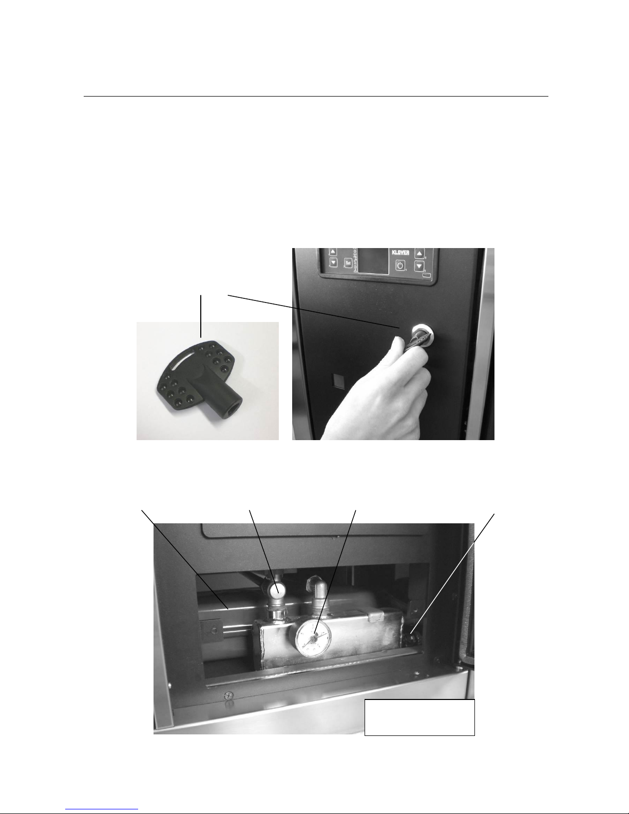
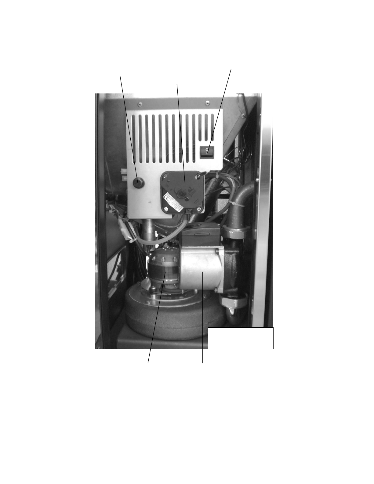
Central heating cooker components…………………………………………………………………….. 8
Connections data sheet (Model with upper flue gas outlet)…………………………………………...12
Connections data sheet (Model with rear flue gas outlet)…………………………………………….. 13
Technical features……………….…………………………………………………………………………14
Pellet features……………………………………………………………………………………………… 15
Requisites of the place of installation………..……………………………………………………..16
Positioning…………………………………………………………………………………………………..16
Spaces around and above the central heating cooker.……………………………………………….. 16
External air vent…………………………………………………………………………………………… 17
Flue and connection to the same –Chimney…………………………………………………………...17
Electric connection……………………………………………………………………………………. 21
Control of any coupled boiler…………………………………………………………………………….. 21
Control of a three-way motorised valve for the DHW system….................................................... 21
Connection to room thermostat….………………………………………………………………………. 22
Pipe connection………………………………………………………………………………………... 23
Connection examples…………………………………………………………………………………….. 24
Cleaning and Maintenance…………………………………………………………………………… 25
Precautions before cleaning……………………………………………………………………………… 25
Routine cleaning……………………………………………………………………………………………25
Extraordinary cleaning……………………………………………………………………………………. 27
Yearly cleaning…………………………………………………………………………………………….. 34
Cleaning the ceramic glass………………………………………………………………………………. 39
Cleaning the flue…………………………………………………………………………………………... 39
Maintenance………………………………………………………………………………………………. 39
The display……………………………………………………………………………………………….40
The menu…………………………………………………………………………………………………43
Commissioning………………………………………………………………………………………… 47
Filling the system for the first time………………………………………………………………………..47
Pellet loading and connection to the mains…………………………………………………………….. 47
Central heating cooker ignition cycle……….…………………………………………………………… 47
Central heating cooker working mode…………………………………………………………………...48
Producing domestic hot water (prepared models only)……………………………………………….. 49
Cooking plate/oven output………………………………………………………………………………...49
Central heating cooker switch-off………………………………………………………………………... 50
Modification of DHW, room and water temperature setting…………………………………………... 51
Alarms signal………………………………………………………………………………………………. 52
It must be known…………………………………………………………………………………………... 52
What happens if….…………………………………………………………………………………….. 53
Circuit board parameters……………………………………………………………………………... 54
Wiring diagram……..……………………………………………………………………………………56
Notes………………………………………………………………………………………………………57
Warranty…………………………………………………………………………………………………. 58

7
INTRODUCTION
Important safety instructions
Read these instructions before installing and using the product.
The central heating cooker installation and commissioning must be performed by skilled
personnel aware of the importance of respecting the Safety Standards in force. They will be
responsible for the definitive installation of the machinery and its consequent proper
operation.
KLOVER srl will not be held responsible if these precautions are not respected.
During installation of the appliance all local regulations, included those referring to National
and European Standards, must be followed.
Connect the product flue gas outlet to a flue that has the features given in the Connections section
in this user guide.
The appliance is not suitable for the installation on a shared flue system.
If the flue should catch fire, you must be provided with appropriate systems for damping down the
fire or call the fire service.
Connect the product to sockets with earth. Avoid using sockets controlled by switches or automatic
timers.
Do not use a damaged or worn power supply cable.
If a multiple socket is used, make sure that the total voltage of the connected devices does not
exceed that supported by the socket. Furthermore make sure that the total voltage of all these
devices connected to the socket does not exceed the maximum level accepted.
Do not use flammable substances to clean the appliance and its elements.
Do not leave flammable containers and substances in the room where the central heating cooker is
installed.
Do not use the appliance as incinerator or in any other way different from that for which it has been
designed.
Do not use fuels different to those which are recommended.
Do not use liquid fuels.
External surfaces of the appliance reach high temperatures when it is running; operate with caution
in order to avoid burns.
Only use original spare parts recommended by the manufacturer.
Do not perform any unauthorised modification to the appliance.
The use of poor pellet or any other material can damage the central heating cooker features,
leading to the termination of the warranty and exempting the manufacturer from all
responsibility.
The Klover pellet products are not suitable for use in smokeless zones.
Some Precautions
Do not touch the hot components of the product (ceramic glass, flue pipe) during normal operation.
Use the appropriate button to switch the electrical panel off. Do not disconnect the power supply
cable while the central heating cooker is running.
Keep children away from the central heating cooker when it is running since they could get burnt by
touching its hot components.
Children and inexperienced people are not allowed to use the appliance.
NEVER open the door of the central heating cooker while it is running.
Conventions used in the manual
Danger to the central heating cooker features.
General danger to personal safety.
Danger to people and objects due to materials at high temperatures.
Danger to people and objects due to electric power.

8
Burns hazard for people due to pressurised hot liquids.
(with temperature not exceeding boiling point at atmospheric pressure).
Destination of use
The new automatic operation SMART 120 central heating cooker by KLOVER has been designed
for heating your home.
The central heating cooker works exclusively with wood pellets and only with the hearth door
shut. Never open the door when the appliance is running.
The central heating cooker has a DOUBLE COMBUSTION system that ensures an extraordinary
efficiency average and “clean” flue gas exhaust with an emission of CO in the atmosphere which is
among the lowest in Europe.
Do not use the central heating cooker in disagreement with the directions contained in this
user guide. The central heating cooker is an indoor product.
This user guide is integral part of the central heating cooker.
If the product is transferred the user must give this manual to the new purchaser.
KLOVER S.R.L. DECLINES ANY RESPONSIBILITY IN CASE OF ACCIDENTS DUE TO THE FAILURE
TO COMPLY WITH THE SPECIFICATIONS OF THIS MANUAL.
FURTHERMORE, KLOVER S.R.L. DECLINES ANY RESPONSIBILITY DUE TO INCORRECT USE OF
THE PRODUCT BY THE USER, MODIFICATION AND/OR UNAUTHORISED REPAIRS, USE OF NON -
ORIGINAL SPARE PARTS OR SIMPLY NOT SPECIFIC FOR THIS PRODUCT.
KLOVER S.R.L. IS NOT RESPONSIBLE FOR INSTALLATION OF THE THERMO STOVE. THE
INSTALLER IS THE ONLY PERSON RESPONSIBLE FOR THIS OPERATION AND HE IS ALSO
ENTRUSTED WITH CHECKING THE FLUE, THE EXTERNAL AIR VENT AND THE CORRECTNESS OF
THE SOLUTIONS SUGGESTED FOR INSTALLATION. ALL THE SAFETY STANDARDS CONTAINED IN
THE SPECIFIC LAW IN FORCE OF THE STATE WHERE THE THERMO STOVE IS INSTALLED MUST
BE RESPECTED.
ROUTINE MAINTENANCE MUST ONLY BE PERFORMED BY AUTHORISED AND QUALIFIED STAFF.
For the validity of the warranty, the user must comply with the directions contained in this
guide and in particular:
Use the central heating cooker according to its operational limits;
All maintenance must be performed constantly;
Only authorise experienced and competent people to use the central heating cooker.
Failure to comply with the requirements of this guide will void the warranty.
Installation Regulations
These operating and instructions cover the basic principles to ensure the correct installation of the pellet
stove, although particulars may need modification to reflect local site conditions. In all cases the installation
must comply with current Building Regulations, Local Authority By-laws and other regulations that affect the
installation of the stove.
The Building Regulations requirements can be met by adopting the relevant recommendations given in
British Standards BS 8303, BS 6461 and BS 7566 as
an alternative means to achieve an equivalent level of performance to that obtained by following the
guidance given in Approved Document J.
Health and Safety
Care must be taken when installing a Klover pellet stove to ensure that the requirements of the Health and
Safety at Work Act are met.
Handling
Adequate facilities must be available for loading, unloading and site handling the appliance bearing in mind
the weight of the appliance.

9
THE MACHINE AND THE PELLETS
Central heating cooker components
The central heating cooker is delivered with the following equipment:
USE, INSTALLATION AND MAINTENANCE GUIDE;
1 POWER SUPPLY CABLE;
1 KEY FOR OPENING TECHNICAL COMPARTMENT;
2 BRUSHES FOR FLUE GAS TURN CLEANING (65 mm and 40 mm diameter).
This manual is an integral part of the machine. Should the central heating cooker be sold, the
manual must be provided to the new purchaser.
SYSTEM
PRESSURE
MANOMETER
BOILER BOILER
AND SYSTEM
LOAD COCK
BOILER BOILER
AND SYSTEM
DRAIN COCK
10 l EXPANSION
VESSEL
KEY FOR OPENING
TECHNICAL
COMPARTMENT
HYDRAULIC
COMPARTMENT

10
MAIN ON/OFF
SWITCH
SAFETY
THERMOSTAT
MANUAL RESET
SYSTEM PUMP
FLUE
PRESSURE
SWITCH
FLUE GAS
INTAKE
DEVICE
TECHNICAL
COMPARTMENT

11
WARNING: the central heating cooker is supplied with already connected power supply cable to anti-
disturbance filter.
AIR VENT MANUAL
VALVE
ANTI-DISTURBANCE
FILTER WITH 2
INCORPORATED
FUSES
(4A 250V) AND
ATTACHMENT FOR
POWER SUPPLY
CABLE
SAFETY VALVE
CALIBRATED AT
2.5 BAR
POWER
BOARD
TECHNICAL
COMPARTMENT SIDE

12
ROOM
THERMOSTAT
CONNECTION
CLAMP
AIR INTAKE PIPE
FLUE
EXHAUST
RETURN
ATTACHM
ENT
DOMESTIC COLD
WATER INLET (ONLY ON
MOD. WITH SET-UP)
+ SYSTEM LOAD AND
BOILER BODY
DOMESTIC HOT
WATER OUTLET
(ONLY ON SET-UP
MOD.)
FLOW
CONNECTION
WITH CHECK
VALVE

13
Connections data sheet (Model with upper flue gas outlet)
M= Ø ¾” F GAS SYSTEM FLOW
R= Ø ¾” M GAS SYSTEM RETURN
C = Ø 14 mm DOMESTIC HOT WATER OUTLET (on prepared models only)
F= Ø 14 mm DOMESTIC COLD WATER INLET
S= Ø 100 mm M FLUE OUTLET
A= Ø 50 mm AIR SUCTION DEVICE
955
250
70
350
295
235
65
170
320
150
115
90
M
R
F
C
A
S
1200
600
875
REAR
VIEW

14
Connections data sheet (Model with rear flue gas outlet)
M= Ø ¾” F GAS SYSTEM FLOW
R= Ø ¾” M GAS SYSTEM RETURN
C = Ø 14 mm DOMESTIC HOT WATER OUTLET (on prepared models only)
F= Ø 14 mm DOMESTIC COLD WATER INLET
S= Ø 100 mm M FLUE OUTLET
A= Ø 50 mm AIR SUCTION DEVICE
350
295
235
170
65
320
150115
90
235
130
M
R
F
C
AS
875
1200
600
REAR
VIEW

15
Technical features
Nominal heat input (reduced)
kW
25,2 (7,5)
Nominal heat output (reduced)
kW
22,7 (6,9)
Nominal heat output given-up to heating water (reduced)
kW
17,5 (4,5)
Nominal heat output given-up to the room (reduced)
kW
5,2 (2,4)
(Reduced) nominal output efficiency
%
90,1 (92)
CO at 13% oxygen at (reduced) nominal heat output
%
0,022 (0,044)
DHW production (Δt = 25°C)
l/min
10
Volume that can be heated at nominal power with a demand of 35 Kcal/m3(45 Kcal/m3)
m3
560 (435)
Nominal voltage
V
220
Nominal frequency
Hz
50
Expansion vessel l/preloading bar
10 / 1
Maximum working pressure/recommended
bar
2,5 / 1,5
Minimum chimney draught at nominal input (reduced)
Pa
12,6 (10)
Combustion gas flow at nominal input (reduced)
g/s
16,2 (9,4)
Exhaust flue gas temperature at nominal input (reduced)
°C
145,1 (69,7)
Pellet tank capacity
Kg
32
Pellet min –max hourly consumption
Kg/h
1,2 –5,1
Operation autonomy at minimum –maximum input
h
27 –7
Boiler body capacity
l
24
FLOW/RETURN heating pipe connections
Ø
3/4” / 3/4"
Domestic water pipe connections
mm
14
Minimum safety distance from flammable materials
mm
200
Flue pipe diameter
mm
100
Width
mm
1200
Height
mm
880
Depth
mm
600
Weight
Kg
290
The manufacturer reserves the faculty to make any modifications to the product in order to improve its
performance.
The given heat output can change according to the pellet used.

16
Pellet features
The central heating cooker has been tested with all types of pellets available on the market. The
pellets used must have the following features:
Diameter 6 mm;
Maximum length 35 mm;
Maximum humidity content 8 –9 %;
100% wood. Total absence of additives.
1.1 % maximum ash residue
For a good performance of the central heating cooker, we recommend using good quality pellets.
Pellets should be poured into the tank using a shovel, and not directly from the bag.
To recognise good quality pellet, make sure:
It is made up of constant diameter cylinders, and has a smooth, glossy surface;
There is not a lot of sawdust inside the packaging;
If the pellet is poured into a container full of water, it will sink if it is good quality, and
it will tend to float if it is not;
The references of quality certifications and in particular compliance with
international standards such as EN 14961-2 Wood pellet class A1-A2 (maximum
moisture level of 10%), should be indicated on the packaging;
Packages are intact as pellet tends to absorb humidity. Humidity not only reduces
the calorific value and increases flue gas, but swells the product, which could create
problems in the central heating cooker.
International standards must be complied with for pellet manufacture as already happens in
France, Austria, Germany, and recently some Eastern countries, which also have to comply with
DIN 51731 and O-NORM M7135 standards in the production phase. These standards establish the
minimum values to check pellet quality. In Italy there are not official rules, but it is recommended
using pellet meeting the previously-mentioned standards.
The use of poor pellet or any other material can damage the central heating cooker features,
voiding the warranty and exempting the manufacturer from all responsibility.
In order to ensure problem-free combustion, the pellets must be kept in a dry place.

17
REQUIREMENTS OF THE PLACE OF INSTALLATION
Positioning
The first step to ensure the best installation of the central heating cooker is to identify an excellent
location; in this regard, take the following elements into account:
The possibility of creating an external air intake;
The possibility of creating a straight flue with possibly coaxial central heating cooker
output;
Proximity to the main liquid collector and /or the boiler if one already exists);
Proximity or ease of connection to the water system;
Ease of access for cleaning the central heating cooker, the exhaust gas ducts and the
flue.
The central heating cooker must be installed on a floor with suitable load capacity. If the existing
building does not meet this requirement, appropriate measures (e.g. load distribution plate) must be
taken.
Once you have found the best location for the cooker arrangement, position it following the directions
given below.
The minimum safety distance from flammable materials must be at least 200 mm from the sides
and back of the central heating cooker.
Spaces around and above the central heating cooker
The figure below shows the minimum measures to be met when positioning the central heating
cooker in relation to the walls.
PARETE POSTERIORE
PARETE LATERALE
PARETE LATERALE
50 cm 50 cm
The hood assembled above the central heating cooker must be at least 70 cm away from its upper
part (also see technical features in the instructions manual attached to the hood to be installed).
Furniture and mobile objects must be positioned at least 10 cm away from the equipment side walls;
these items should be easily removable in case of maintenance work. In any case they should
be moved before any operation by the authorised Technical Assistance Centre for easy
access to the equipment sides.
Hanging shelves or building countertops above the central heating cooker, especially if the latter
have low heat resistance, is not recommended. Shelves or countertops should in any case be at
least 70 cm away from the upper cooking plate.
Protect all structures that can catch fire from heat radiation.
REAR WALL
LATERAL WALL
LATERAL WALL

18
External air vent
While running the central heating cooker draws air from the room in which it is installed; It is
essential, therefore, that the air is restored through an external air vent.
An air vent must be made at the back of the equipment (15 cm diameter hole), at a height of
20 cm from the ground, near the central heating cooker intake pipe (see figure A and
Connections technical sheet).
if the rear external air vent does not draw air directly from outside the home, a further hole in an
adjacent room must be made provided it communicates with the outside of the home (minimum
diameter 15 cm).
If an air vent cannot be made on the heating cooker rear wall, keep it at least 5 cm away from the
rear wall and drill a hole (diameter as above) in a perimeter wall of the room where the central
heating cooker is installed.
The hole must be protected externally with a fixed grid. Periodically ensure the grid is not
obstructed by leaves or the like, thereby preventing air passage.
The UNI 10683 standard PROHIBITS the withdrawal of combustion air from garages, fuel
stores, or businesses involving a fire hazard.
Do not connect the external air vent to the central heating cooker through piping. If there are
other heating or suction appliances in the room, air vents must ensure the necessary air
volume required for the proper operation of all devices.
In the room where the central heating cooker is to be installed, only sealed equipment (e.g. C
type gas equipment, according to the UNI 7129 Standard), or equipment that does not cause
depression with respect to the external environment can be kept or be installed.
Extractor fans may cause a malfunction in the central heating cooker when used in the same room
or operational space as the cooker.
Figura A
Flue and connection to the same flue - Chimney
The flue is a key element for the proper operation of the central heating cooker. The minimum section
of the flue must be the one indicated in the central heating cooker specifications (120 mm). Each
central heating cooker must have its own flue, without other intakes (boilers, fireplaces, stoves,
etc…). The flue size is closely related to its height, to be measured from the central heating cooker
outlet to the chimney base. To ensure draught, the chimney flue outlet surface must be twice as big
as the flue section.

19
The exhaust duct of the combustion products, generated by the forced draught unit, must meet the
following requirements:
Be airtight to combustion products, waterproof, and properly insulated according to the
conditions of use (see UNI 9615);
Being made of materials suitable to resist normal mechanical stress, heat, action of the
combustion products, and condensate if any;
Have ascending development after the vertical tract for the entire remaining path with a
5% minimum slope. The sub-horizontal development part must not have a length greater
than ¼ of the effective height of the flue or chimney, and in any case not be longer than
2,000 mm;
Have a preferably circular internal section: square and rectangular sections should have
rounded corners with a radius larger than 20 mm;
To have constant, free and independent internal section;
To have rectangular sections with a 1.5 maximum ratio between sides;
If the flue is installed outdoors or in a cold room (e.g. boiler room) it is absolutely
necessary that it is insulated to prevent cooling of the fumes and the formation of
condensate;
To mount exhaust channels (stretching from the unit to the flue inlet), elements of non-
combustible materials suitable for resisting combustion products and any condensation
must be used;
It is forbidden to use fibre cement pipes to connect the appliances to the flue;
Exhaust channels must not pass through rooms in which the installation of combustion
appliances is forbidden;
When mounting exhaust channels, make sure they are flue gas sealed;
Installation of horizontal sections should be banned;
The usage of elements in counter-slope is forbidden;
The exhaust channel must allow soot recovery or cleaning using a swab, and must have
a constant section;
It is forbidden to run other air supply channels and pipes for plant engineering use into the
exhaust channels, even if oversized.
The chimney is a device crowning the flue, used to facilitate the dispersion of combustion products.
It must meet the following requirements:
Have a useful outlet section not smaller than twice that of the flue on which it is inserted;
Be shaped so as to prevent the penetration of rain and snow into the flue;
Be built in such a way that combustion discharge is ensured even in case of wind in any
direction and angle.
The outlet height (where height corresponds to the top of the flue, regardless of any chimneys) must
be beyond the so-called reflow area in order to avoid the formation of counter-pressures preventing
the free discharge of combustion products into the atmosphere.
It is therefore necessary to ensure compliance with the minimum heights shown in the following
figures:
Technical
volume
0,5 m
0,5 m
Distance > 5 m Distance < 5 m Distance> 1,85 m
Distance< 1,85 m
0,5 m over
the ridge
Reflow zone
1m minimum
15°

20
FURTHER SPECIFICATIONS TO BE CONSIDERED
The central heating cooker works with the combustion chamber in depression; it is essential that the
exhaust pipe is hermetically sealed.
We recommend using rigid stainless steel pipes, with sealing gaskets having a minimum diameter of
120 mm.
The pipes must be double-walled or adequately insulated with rock wool. The maximum
temperature of the pipe must not exceed 70 °C.
TO ENSURE PROPER FUME DISCHARGE PROVIDE FOR AN INITIAL VERTICAL TRACT OF AT
LEAST 1.5 METRES.
Each change of direction must be carried out with a T-shaped fitting and inspection cap.
Pipes must ensure sealing against smoke leakage via gaskets resistant to 250 °C.
Fix the pipes to the wall with suitable relevant metal collars to avoid any vibration.
WARNING: IT IS FORBIDDEN TO INSTALL DRAUGHT REGULATING VALVES (BUTTERFLY
VALVES).
There are two solutions for the connection to the flue:
SOLUTION 1 –REAR FLUE GAS OUTLET
Other manuals for SMART 120
1
Table of contents