Klutch 57392 User manual

1/2In. Mini Air Regulator
Owner’s Manual
WARNING: Read carefully and understand all ASSEMBLY AND OPERATION
INSTRUCTIONS before operating. Failure to follow the safety rules and other basic safety
precautions may result in serious personal injury.
Item #57392

Page 2 of 13
Thank you very much for choosing a Klutch™product!
For future reference, please complete the owner’s record below:
Serial Number/Lot Date Code: ________________________________
Purchase Date: ____________________________________________
Save the receipt, warranty, and this manual. It is important that you read
the entire manual to become familiar with this product before you begin
using it.
This air regulator is designed for certain applications only. Northern Tool
& Equipment is not responsible for issues arising from modification or
improper use of this product such as an application for which it was not
designed. We strongly recommend that this product not be modified
and/or used for any application other than that for which it was designed.
For technical questions, please call 1-800-222-5381.

Page 3 of 13
Table of Contents
Intended Use..........................................................................................................................................4
Technical Specifications......................................................................................................................4
Important Safety Information...............................................................................................................4
Specific Operation Warnings...............................................................................................................6
Main Parts of Product...........................................................................................................................7
Assembly Instructions..........................................................................................................................8
Before Each Use....................................................................................................................................8
Operating Instructions..........................................................................................................................8
Maintenance ..........................................................................................................................................9
Troubleshooting....................................................................................................................................9
Parts Diagram......................................................................................................................................10
Parts List..............................................................................................................................................11
Replacement Parts..............................................................................................................................11
Limited Warranty.................................................................................................................................12

Page 4 of 13
Intended Use
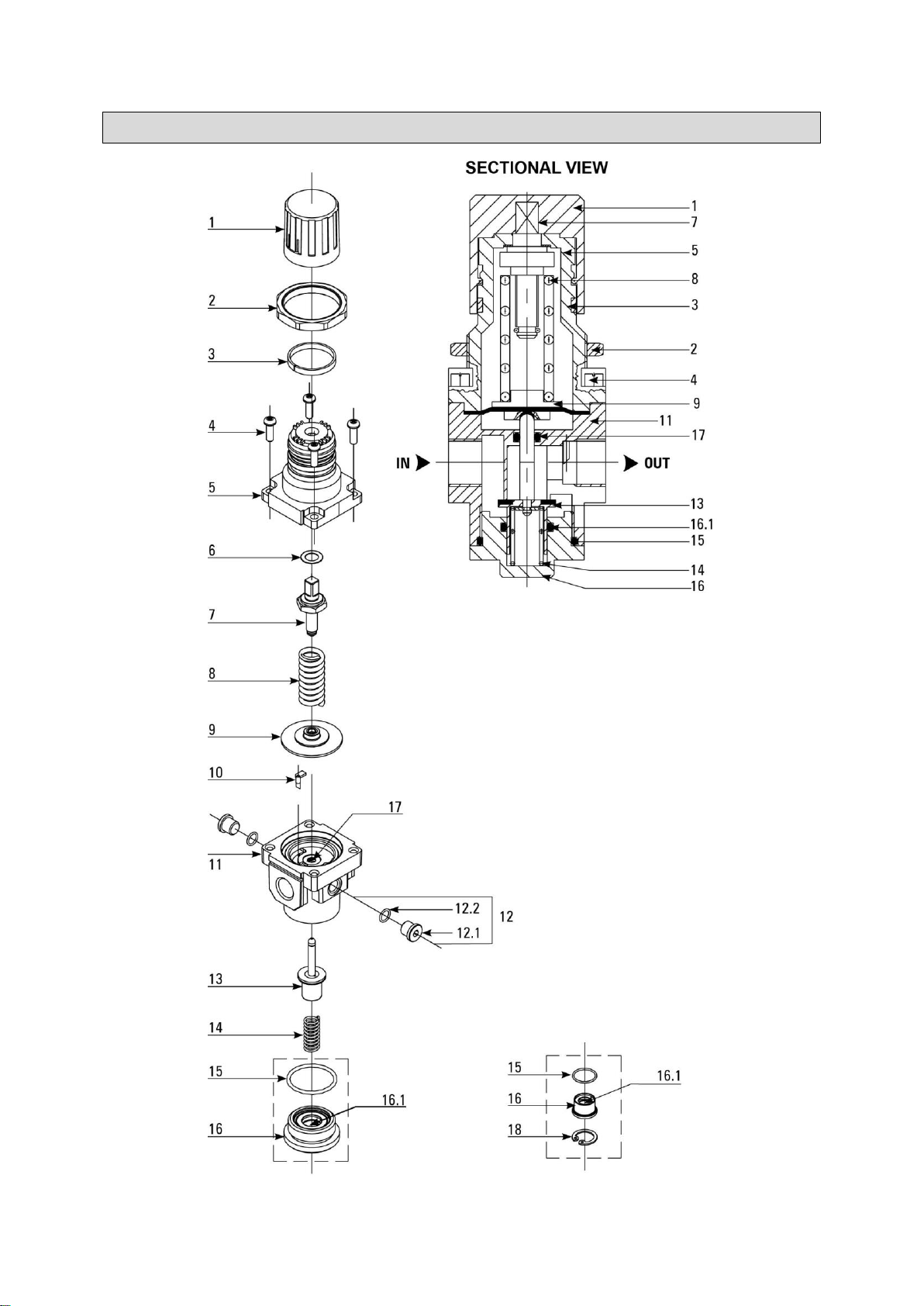
One of the most commonly used air line accessories, regulators are used to maintain a steady outlet
pressure, unaffected by variations/fluctuations in the inlet pressure. Regulators step down the air line
pressure and can be set at any desired pressure below the inlet air pressure. With an aluminum die
cast body, these are designed with a non-raising “press to lock” adjusting knob for locking at any set
pressure. Regulators work on a diaphragm operated, relieving mechanism with pressure
compensated by a balanced poppet. These can be installed in any position.
WHY USE A REGULATOR?
Air regulators are used to provide a controlled and consistent air supply as required by different
pneumatic equipment. The knob can be used to adjust the air supply thus resulting in increasing or
decreasing the air pressure.
WETTED COMPONENTS
Aluminum, Brass, Steel, Acetal, Stainless Steel, and Nitrile
STANDARD CONFIGURATION
Pressure adjustment range of 7 - 145 PSI (0.5 - 10 BAR)
OPTIONAL CONFIGURATION
Custom built includes the following pressure adjustment ranges:
3 - 28 PSI (0.2 - 2 BAR)
3 - 58 PSI (0.2 - 4 BAR)
8 - 100 PSI (0.5 - 7 BAR)
Technical Specifications
Part #
Port
Size
Flow Rate (Max)**
Pressure Gauge
Port Size
Height
Width
CFM
LPM
Inch
mm
In
mm
57392
½”
140
4000
1/8”
6.5
165
2.75
70
Important Safety Information
⚠WARNING
Read and understand all instructions. Failure to follow all instructions may result in serious injury
or property damage.
The warnings, cautions, and instructions in this manual cannot cover all possible conditions or
situations that could occur. Exercise common sense and caution when using this tool. Always be
aware of the environment and ensure that the tool is used in a safe and responsible manner.
Do not allow persons to operate or assemble the product until they have read this manual and
have developed a thorough understanding of how it works.
Do not modify this product in any way. Unauthorized modification may impair the function and/or
safety and could affect the life of the product. There are specific applications for which the product
was designed.
Use the right tool for the job. DO NOT attempt to force small equipment to do the work of larger
industrial equipment. There are certain applications for which this equipment was designed. It will
be a safer experience and do the job better at the capacity for which it was intended. DO NOT use

Page 5 of 13
this equipment for a purpose for which it was not intended.
Industrial or commercial applications must follow OSHA requirements.
⚠WARNING
WORK AREA SAFETY
Inspect the work area before each use. Keep work area clean, dry, free of clutter, and well-lit.
Cluttered, wet, or dark work areas can result in injury. Using the product in confined work areas
may put you dangerously close to other cutting tools and rotating parts.
Do not use the product where there is a risk of causing a fire or an explosion; e.g., in the presence
of flammable liquids, gases, or dust. The product can create sparks, which may ignite the
flammable liquids, gases, or dust.
Keep children and bystanders away from the work area while operating the tool. Do not allow
children to handle the product.
Be aware of all power lines, electrical circuits, water pipes, and other mechanical hazards in your
work area. Some of these hazards may be hidden from your view and may cause personal injury
and/or property damage if contacted.
⚠WARNING
PERSONAL SAFETY
Stay alert, watch what you are doing, and use common sense when operating the tool. Do not use
the tool while you are tired or under the influence of drugs, alcohol, or medication. A moment of
inattention while operating the tool may result in serious personal injury.
Dress properly. Do not wear loose clothing, dangling objects, or jewelry. Keep your hair, clothing
and gloves away from moving parts. Loose clothes, jewelry, or long hair can be caught in moving
parts. Air vents on the tool often cover moving parts and should be avoided.
Wear the proper personal protective equipment when necessary. Use ANSI Z87.1 compliant safety
goggles (not safety glasses) with side shields, or when needed, a face shield. Use a dust mask in
dusty work conditions. Also use non-skid safety shoes, hardhat, gloves, dust collection systems,
and hearing protection when appropriate. This applies to all persons in the work area.
Do not overreach. Keep proper footing and balance at all times.
⚠CAUTION
AIR REGULATOR USE AND CARE
Do not force the air regulator. Products are safer and do a better job when used in the manner for
which they are designed. Plan your work, and use the correct product for the job.
Check for damaged parts before each use. Carefully check that the product will operate properly
and perform its intended function. Replace damaged or worn parts immediately. Never operate the

Page 6 of 13
product with a damaged part.
Store the air regulator when it is not in use. Store it in a dry, secure place out of the reach of
children. Inspect the tool for good working condition prior to storage and before re-use.
Use only accessories that are recommended by the manufacturer for use with your product.
Accessories that may be suitable for one product may create a risk of injury when used with
another tool. Never use an accessory that has a lower operating speed or operating pressure than
the tool itself.
Specific Operation Warnings
⚠WARNING
Do not exceed the PSI rating.
Wear ANSI Z87.1 compliant eye protection during use.

Page 7 of 13
Main Parts of Product
Ref #
Description
Qty.
1
Knob
1
2
Locknut
1
3
Indicator Ring
1
4
Philip Head Screw
4
5
Bonnet
1
6
Bearing Washer
1
7
Adjusting Screw Assembly
1
8
Main Spring
1
9
Diaphragm Assembly
1
10
Venturi Tube
1
11
Housing
1
12
Port Plug Assembly
2
12.1
Port Plug
2
12.2
O-Ring
2
13
Valve Cone Assembly
1
14
Bottom Spring
1
15
O-Ring
1
16
Bottom Plug
1
16.1
O-Ring
1
17
O-Ring
1
18
Circlip
1

Page 8 of 13
Assembly Instructions
1. Install in a clean/ acid free atmosphere.
2. Flush the piping for dirt, dust, and other foreign particles.
3. Use proper thread sealant for taper threads to create a leak-proof connection.
4. Screw the Inlet/Outlet pipe with the respective port.
5. Open the inlet valve/ switch on the air supply.
6. When using (G) parallel thread nipples, check the length of the thread from the given table.
Thread
Size
Tightening Torque,
Lb. - In (Nm)
Length (L) of
Thread
G1/2
250-270 (28-30)
12mm Max.
Before Each Use
WHERE TO INSTALL A REGULATOR?
As close as possible to the tool or equipment to avoid any further pressure loss.
Between the filter and lubricator.
With arrows pointing in the direction of air flow (towards tool/equipment).
WHERE TO INSTALL APRESSURE GAUGE?
Pressure gauges must be installed on the pressure gauge port on the Regulator. Regulator has 1/8”
pressure gauge port. The Pressure gauge must also be of 1/8” port size. Steps to install the pressure
gauge:
Unscrew the bolt on the pressure gauge port.
Replace the bolt with the corresponding size Pressure Gauge.
Pressure Gauge can be installed on any of the two Pressure Gauge ports on the Regulator.
NOTE: Pressure Gauge may not be included as a standard accessory, but can be purchased
separately.
Operating Instructions
1. To set the regulator, pull the regulating knob till “Red Band” (Indicator Ring) is visible.
2. To increase the pressure, turn the regulating knob in a clockwise direction.
3. To reduce the pressure, turn the regulating knob in a counter clockwise direction.
4. Set the pressure within the specified pressure range.

Page 9 of 13
Maintenance
1. Before dismantling the unit, exhaust the air in the line completely.
2. Dismantle the components and clean them in kerosene and blow with compressed air.
3. Check for damages in the O-rings (15), (16.1), (17) and at sealing areas in the valve cone
rubber, spherical relieving seating, seating area of the housing, etc. Replace if needed or
clean and reassemble.
4. For assembly of the unit: Apply general purpose grease on the O-rings (15), (16.1), (17) and
on the cylindrical surface of the valve cone (13), on threads of the adjusting screw (7), and on
bearing washer (6). Reassemble all the components.
Troubleshooting
Use the table below to troubleshoot problems before contacting service personnel or your local
dealer. If the problem continues after troubleshooting, call your local dealer for assistance.
Failure
Possible Cause
Corrective Action
Continuous leak through the
knob (1).
Diaphragm (9) damaged.
Replace Diaphragm assembly (9).
Relieving spherical seating
of the valve cone damaged.
Replace valve cone assembly (13).
Dirt found in between the
seating and the valve cone
(13).
Clean and reassemble.
O-ring (16.1) damaged.
Replace the o-ring (16.1).
Air leaks through housing
and bottom plug (16)
interface.
O-ring (15) damaged.
Replace the o-ring (15).
Setting pressure goes on
increasing slowly.
Relieving spherical seat of
the valve cone damaged.
Replace the valve cone assembly (13).
Dirt found in between the
seating and the valve cone.
Clean and reassemble.
O-ring (16.1) damaged.
Replace the o-ring (16.1).
After frequent use of
adjustment knob, the
pressure setting
becomes
impossible.
Wearing out of the adjusting
Screw (7).
Replace the adjusting screw assembly
and apply general purpose grease on
threads and at washer (6).
Supply pressure directly
connected to outlet
port and making
pressure setting
impossible.
Valve cone assembly (13)
is stuck.
Dismantle the valve assembly (13).
Clean using kerosene and air jet.
Reassemble after applying general
purpose grease on o-ring (17) and on
the valve cone cylindrical portion.

Page 10 of 13
Parts Diagram

Page 11 of 13
Parts List
Reference
Item Description
Quantity
1
Knob
1
2
Locknut
1
3
Indicator Ring
1
4
Philip Head Screw
4
5
Bonnet
1
6
Bearing Washer
1
7
Adjusting Screw Assembly
1
8
Main Spring
1
*
0.2 - 2 BAR (3 - 28 PSI)
*
*
0.2 - 4 BAR (3 - 58 PSI)
*
*
0.5 - 7 BAR (8 - 100 PSI)
*
*
0.5 - 10 BAR (8 - 145 PSI)
*
9
Diaphragm Assembly
1
10
Venturi Tube
1
11
Housing
1
12
Port Plug assembly
2
12.1
Port Plug
2
12.2
O-Ring
2
13
Valve Cone Assembly
1
14
Bottom Spring
1
15
O-Ring
1
16
Bottom Plug
1
16.1
O-Ring
1
17
O-Ring
1
18
Circlip
1
Replacement Parts
For replacement parts and technical questions, please call Customer Service at 1-800-222-5381.
Not all product components are available for replacement. The illustrations provided are a
convenient reference to the location and position of parts in the assembly sequence.
When ordering parts, the following information will be required: item description, item model
number, item serial number/item lot date code, and the replacement part reference number.
The distributor reserves the rights to make design changes and or improvements to product lines
and manuals without notice.

Page 12 of 13
Limited Warranty
Northern Tool and Equipment Company, Inc. ("We'' or '"Us'') warrants to the original purchaser only
("You'' or “Your”) that the Klutch product purchased will be free from material defects in both materials
and workmanship, normal wear and tear excepted, for a period of one year from date of purchase.
The foregoing warranty is valid only if the installation and use of the product is strictly in accordance
with product instructions. There are no other warranties, express or implied, including the warranty of
merchantability or fitness for a particular purpose. If the product does not comply with this limited
warranty, Your sole and exclusive remedy is that We will, at our sole option and within a commercially
reasonable time, either replace the product or product component without charge to You or refund the
purchase price (less shipping). This limited warranty is not transferable.
Limitations on the Warranty
This limited warranty does not cover: (a) normal wear and tear; (b) damage through abuse, neglect,
misuse, or as a result of any accident or in any other manner; (c) damage from misapplication,
overloading, or improper installation; (d) improper maintenance and repair; and (e) product alteration
in any manner by anyone other than Us, with the sole exception of alterations made pursuant to
product instructions and in a workmanlike manner.
Obligations of Purchaser
You must retain Your product purchase receipt to verify date of purchase and that You are the original
purchaser. To make a warranty claim, contact Us at 1-800-222-5381, identify the product by make
and model number, and follow the claim instructions that will be provided. The product and the
purchase receipt must be provided to Us in order to process Your warranty claim. Any returned
product that is replaced or refunded by Us becomes our property. You will be responsible for return
shipping costs or costs related to Your return visit to a retail store.
Remedy Limits
Product replacement or a refund of the purchase price is Your sole remedy under this limited warranty
or any other warranty related to the product. We shall not be liable for: service or labor charges or
damage to Your property incurred in removing or replacing the product; any damages, including,
without limitation, damages to tangible personal property or personal injury, related to Your improper
use, installation, or maintenance of the product or product component; or any indirect, incidental or
consequential damages of any kind for any reason.
Assumption of Risk
You acknowledge and agree that any use of the product for any purpose other than the specified
use(s) stated in the product instructions is at Your own risk.
Governing Law
This limited warranty gives You specific legal rights, and You also may have other rights which vary
from state to state. Some states do not allow limitations or exclusions on implied warranties or
incidental or consequential damages, so the above limitations may not apply to You. This limited
warranty is governed by the laws of the State of Minnesota, without regard to rules pertaining to
conflicts of law. The state courts located in Dakota County, Minnesota shall have exclusive jurisdiction
for any disputes relating to this warranty.

Page 13 of 13
Distributed by:
Northern Tool & Equipment Company, Inc.
Burnsville, Minnesota 55306
www.northerntool.com
Made in India
Table of contents