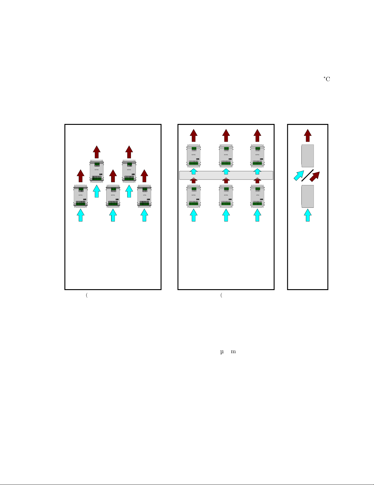
2.3 Installation of KATKA into cabinet
During normal operation, modules produce great amount of heat. Therefore it’s necessary to provide sufficient
air flow in the cabinet (holes in bottom and top of the cabinet) and sometimes also use of active cooling (use
of fan) might be necessary. Modules have to be installed vertically to allow air to flow through heatsink from
bottom to top. Ambient temperature (air provided for cooling of the module) should be kept bellow 45
°
C.
When installing multiple rows of modules in one cabinet each row should be staggered or heat deflectors
should be used. Air coming out of the module is very hot and might have negative effect to module directly
above. Modules should be installed to higher levels so hot air can escape cabinet as soon as possible.
KATKA
L1 C1 L2 C2 L3 C3
L1 L2 L3
KATKA
L1 C1 L2 C2 L3 C3
L1 L2 L3
KATKA
L1 C1 L2 C2 L3 C3
L1 L2 L3
KATKA
L1 C1 L2 C2 L3 C3
L1 L2 L3
KATKA
L1 C1 L2 C2 L3 C3
L1 L2 L3
(a) Staggered placing
KATKA
L1 C1 L2 C2 L3 C3
L1 L2 L3
KATKA
L1 C1 L2 C2 L3 C3
L1 L2 L3
KATKA
L1 C1 L2 C2 L3 C3
L1 L2 L3
KATKA
L1 C1 L2 C2 L3 C3
L1 L2 L3
KATKA
L1 C1 L2 C2 L3 C3
L1 L2 L3
KATKA
L1 C1 L2 C2 L3 C3
L1 L2 L3
(b) Use of heat deflectors
Figure 3: Installation example
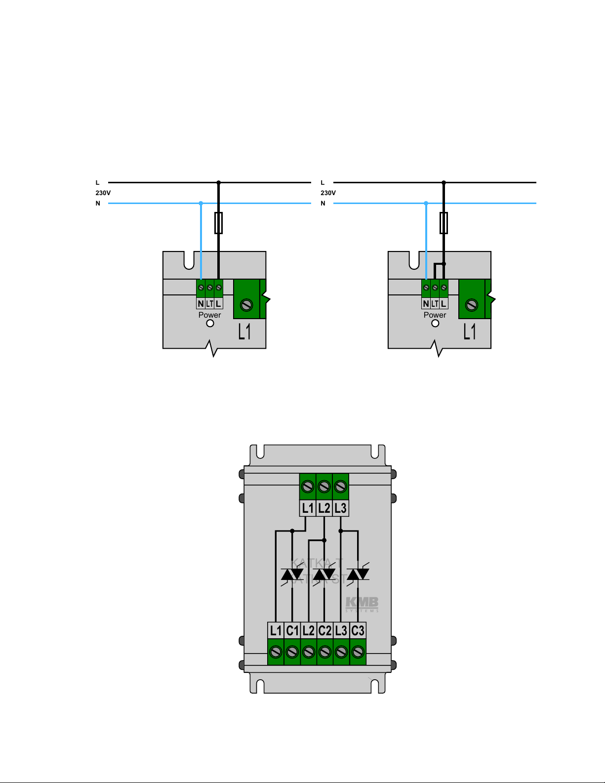
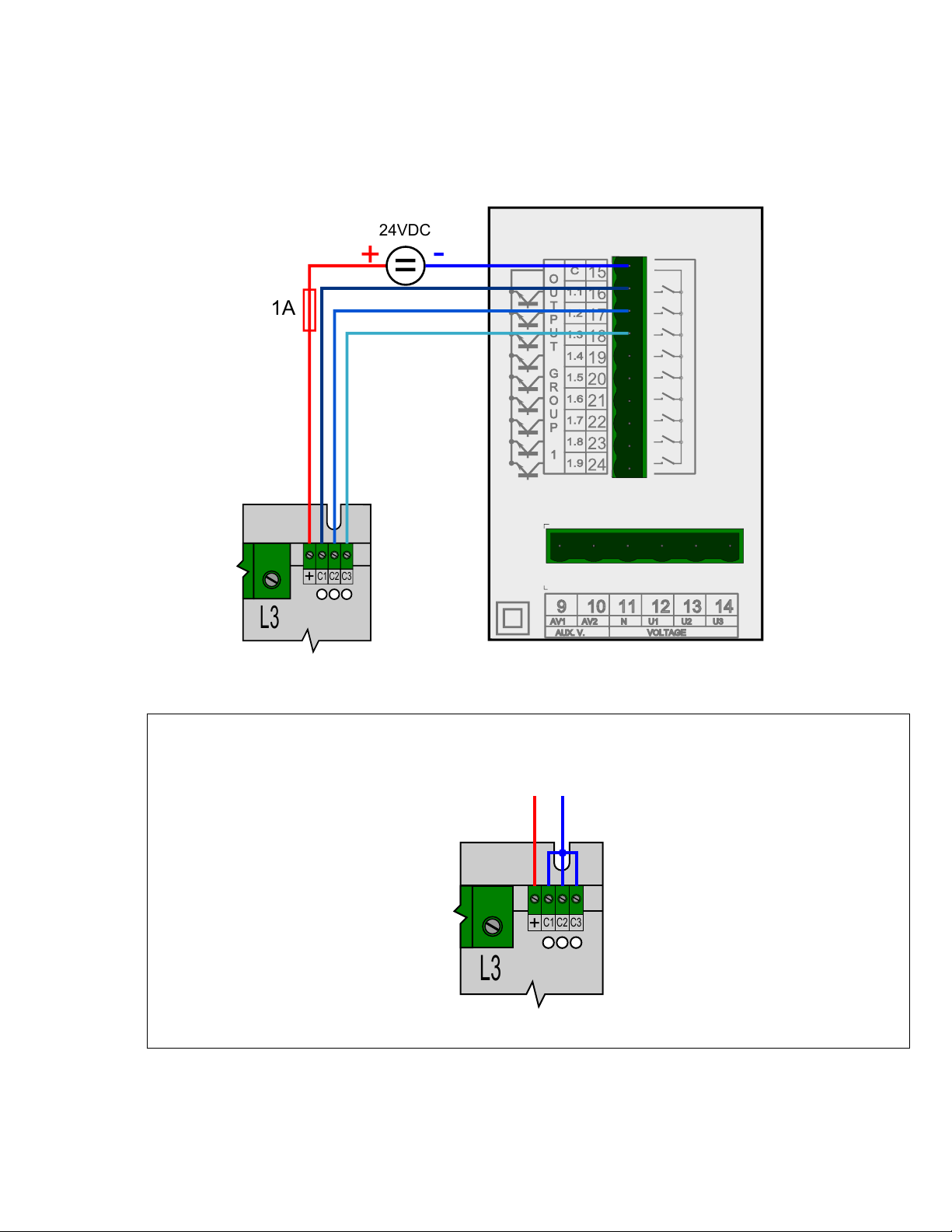
2.4 Connection of Load
When using power factor correction capacitors, implementation of detuned power factor correction is
highly recommended, otherwise an inductance of at least 12
µ
H must be wired in series with the switch to
prevent thyristor damage by reducing speed of current rise. A detuning reactor also expands life of power factor
correction capacitors and improves control accuracy. The modules incorporate class C over-voltage protection
varistors. It is further recommended that a class B, 50 kA, lightning current protection device should be installed
in the power lead.
5