KMT RPM-8000-PRO User manual

KMT - Kraus Messtechnik GmbH
Gewerbering 9, D-83624 Otterfing, Germany, 08024-48737, Fax. 08024-5532
Home Page: http://www.kmt-telemetry.com, Email: info@kmt-telemetry.com
O
Op
pe
er
ra
at
ti
in
ng
g
i
in
ns
st
tr
ru
uc
ct
ti
io
on
ns
s
R
RP
PM
M-
-8
80
00
00
0-
-P
PR
RO
O
INSTRUCTIONS FOR QUALIFIED PERSONNEL ONLY!

Version 2012-10 2Technical Data are subject to change without notice!
Operating principle
Considering the simplest physical generator with a rotating
wire winding inside a magnetic field produced by two magnetic
poles (one pole pair = north and south) - the output voltage is a
sine wave (blue line) with one cycle per revolution. After
rectification with diodes we get an alternating DC voltage with
2 pulses per revolution (black line) and a resulting average
voltage (brown line).
To imagine a three-phase generator we add two independent
wire windings. Now we have 3 sine wave voltages which are
spaced about 120° out of phase. After three-way rectification
with six diodes the result is an alternating DC voltage with 6
pulses per revolution (black line) and an increased average
voltage against the generator with one winding.
In practice generators for automobiles have more than two
poles. In most cases here we find 12 poles (6 pole pairs) and
sometimes also 16 poles (8 pole pairs). For the first one we get
from every phase 6 cycles per revolution and after rectification
an alternating DC voltage with 36 pulses.
The board net voltage ripple frequency can simply calculated
by multiplying the alternator RPM with the number of poles
(e.g. 12*2=24) and the number of phases (3). 12*2*3 = 72
Приводной ремень
Генератор
Двигатель
By connecting to an automotive cigarette lighter socket the
measurement unit RPM-8000 PRO senses the small AC ripple
of the vehicle board net DC supply voltage and generates on
its outputs both a TTL digital pulse train and an analog voltage
signal. These signals are “per design” linear to the alternator
RPM and by the linear drive belt relationship also to the engine
RPM. The scaling factor can determined by the relation
between the effective diameters of the engine andthe
alternator pulleys.
Accuracy:
Next diagram shows a part of a test measurement of a famous
German automobile manufacturer. The RPM reference signal
was obtained from the car internal CAN bus, which will also
used for the electronically engine management. To verify the
dynamical performance, the RPM signal was provide with an
additional scaling factor of 1.02 - actually both curves are
congruent.
In practice the generated alternator ripple also includes
electrical noise and disturbances from other electrical devices
and loads connected to the vehicle supply. In petrol engine
vehicles this is mainly due to the ignition system and is
relatively straight-forward to eliminate. In Diesel engine
vehicles however the main noise source is from the electronic
injection system and, due to the spectral content of the
injection signals, is very difficult to decouple from the relatively
small signal of interest from the alternator. This technical
background helps to explain the different accuracies of the
RPM signal, which are achieved: approx. 0.5% for Petrol and
approx. 1.5% for Diesel engines. To improve the signal-to-
noise ratio, additional resistive loads such as rear window
heater and lights (not gas discharge lamps) should be
turned on. All inductive loads such as air conditioning
system, air blower, light dimmer, sliding roof and door
opener should remain off! This process increases the
accuracy of the output signal in every case
v
t
T
v
t
T
v
t
T

Version 2012-10 3Technical Data are subject to change without notice!
General description
RPM-8000-PRO offers a discerning solution for automotive RPM measurement without an additional sensor: the practical
instrument is simply connected via a standard jack to the cigarette lighter socket and the RPM is shown directly on the LCD
display. You even have the choice to output the data as an analog voltage (1 Volt per 1000 rev/min) or as a digital pulse
sequence, 1:1 ripple of the alternator (TTL). The smart measuring principle is based on an analysis of the ripple balance of the
supply system, characteristic for all automotive alternators. The frequency (TTL) of this ripple amounts to about 100 to 120
pulses per engine rotation and therefore delivers good dynamic measuring results.
Though the frequency is proportional to the engine RPM, it also depends on the gear transmission ratio from
crankshaft/alternators and on the number of alternators poles and phases. This makes the calibration of the input signal to the
actual measured RPM necessary. The latest version of the RPM-8000-PRO now offers two elegant options:
Internal calibration: The internal calibration assumes a steady engine RPM of 2000 rev/min (drive e.g. in the 2. gear and had
hold 2000 RPM), which can be monitored by the automotive tachometer. By pushing the “Cal. Int” button and keep the button
pressed until the red LED stops flashing, and is permanently illuminated.
External calibration (option): A laser RPM ”RPM-LASER-CAL” is needed for this option. A reflector tag is mounted on the
main belt disc and scanned by laser beam. The TTL output of the laser instrument is connected via cable to the “Ext. Cal In.”
input of the RPM-8000-PRO and delivers one pulse per rotation. (don’t press the “Cal Int” Button for Ext.). By comparing the
pulse sequence with the measured pulse frequency, the instrument calculates automatically the relationship between ripple
balance and speed. Identical displays on laser and RPM-8000-PRO signal successful calibration (also shown by luminescent
LED’s).
The measuring range of the analog output can be varied on demand via jumpers (e.g. to 0.5, 1.0 or 2.0 Volt per 1000 rev/min).
The TTL output can also be scaled with a frequency factor of 1:8 or 1:16 –and therefore adapted to the resolution ability of
attached measuring systems. For software setting purposes, the number of pulses per (e.g. 80-120) revolution is indicated by
pressing the yellow TTL button, independently of the digital output divider (TTL Div). The instrument saves the calculated
calibration data in non-volatile memory until the next calibration.

Version 2012-10 4Technical Data are subject to change without notice!
Functions and display:
Internal calibration
When the vehicle tachometer
registers a constant speed of
2000 rev/min, keep the Cal. Int.
button pressed until the red LED
stops flashing, and is
permanently illuminated
To battery or cigarette
lighter sockets - 12-42V
TTL button
Switches the screen to number
of pulses per revolution, as
long as the button is pressed.
TTL out (output)
Divider for digital output:
1:1 or 8:1 or 16:1
For example:
4000 Hz TTL at div. 1 position
500 Hz TTL at div. 8 position
250 Hz TTL at div. 16 position
SYNC OK LED
Lights up when
RPM8000Pro is
synchronized with the
engine speed.
Analog output
0-10V
Connection for LASER RPM
tachometer
Don't press the CAL button
during external calibration!!
(Self detection of EXT Cal
input!)
Dig. output
0-5V TTL
Power ON LED
Lights up when 12-42V is
applied to the cigarette
lighter.
LCD screen
Indicates the actual speed
or the number of pulses
per revolution is indicated
by pressing the yellow TTL
button

Version 2012-10 5Technical Data are subject to change without notice!
External calibration with laser-based tachometer:
Attach a reflector tag (approximately 10 mm long) to the calibration shaft (crankshaft).
Plug the RPM-8000-PRO into the cigarette lighter socket outlet or connect directly to the battery. Make sure
polarity is correct when connecting to the battery.
Start engine –turn on lights and rear window heater –turn off the air conditioning system and other inductive
loads –run engine at constant no-load speed –connect TTL output from laser to “Cal. Ext. In” jack on the RPM-
8000-PRO.
Point the laser beam at the reflector tag at an angle of about 90°. The RPM-8000-PRO is calibrated when both
the laser and the RPM-8000-PRO show the same speed, the red LED stops flashing and the green LED is
permanently illuminated. The calibration data is stored permanently in the device and therefore is not lost when
power is turned off. The data is only overwritten when the device is recalibrated.
The “Cal Int.” button should not be pressed while using the external calibrated process. The RPM-8000-PRO
is now set to the actual speed of the shaft with reflector tag and is shown on the screen. A DC voltage of 1V per
1000 rev/min is applied to the analog output.
Cigarette lighter plug
External laser tachometer
”RPM-LASER-CAL”
LEMO-BNC adapter cable

Version 2012-10 6Technical Data are subject to change without notice!
RPM-Laser-CAL general function-2.1:

Version 2012-10 7Technical Data are subject to change without notice!
RPM-Laser-CAL general function-2.2:

Version 2012-10 8Technical Data are subject to change without notice!
Internal calibration using the Cal button:
Internal calibration requires that the engine is running at a speed of 2000 rev/min, as shown on the tachometer in
the vehicle (ideally calibration should be carried out when the vehicle is being driven, that is, moving). When this
speed is reached, press and hold “Cal. Int.” button until the red LED stops flashing and is permanently illuminated.
Calibration is than completed and the calibration value is stored permanently in the device even after power is
turned off. The calibration value is only deleted if the “Cal. Int.” button is pressed again: the old calibration value is
then replaced by the newvalue. (The same applies to external calibration). The actual engine speed appears on the
screen and the analog output returns 1V per 1000 rev/min.
During calibration and during the entire test you should turn on all resistive loads such as lights and rear window
heater; and turn off all inductive loads such as the air conditioning system, sliding roof, power windows and
ventilation. You shouldn't use an external laser tachometer during internal calibration!!.
When a constant speed of
2000 rev/min is registered
by the vehicle tachometer,
press the Cal. Int. button
until the red LED stops
flashing, and remains
constantly illuminated.
2.000

Version 2012-10 9Technical Data are subject to change without notice!
Starting up the RPM 8000 PRO revolution counter:
The RPM-8000-PRO is designed to operate at 12 - 42V DC. You can use our battery adaptor to connect directly to battery
terminals.
Caution!!!!!
Red = Plus ++
Black = Minus --
A polarity mismatch will inevitably cause
damage to the device and voids the
warranty!!
When connecting to the vehicle electrical distribution system instead of the cigarette-lighter socket, always make sure the polarity
of the connection cable is correct. If you have contact problems with some makes of cigarette lighters you should use an adapter
cable (from a different connector type to a standard socket) to avoid inadvertently reversing the connection terminals.
To improve the signal-to-noise ratio, additional resistive loads such as rear window heater and lights (not gas discharge lamps)
should beturned on. All inductive loads such as air conditioning system, air blower, light dimmer, sliding roof and door opener
should remain off! This process increases the accuracy of the output signal in every case.
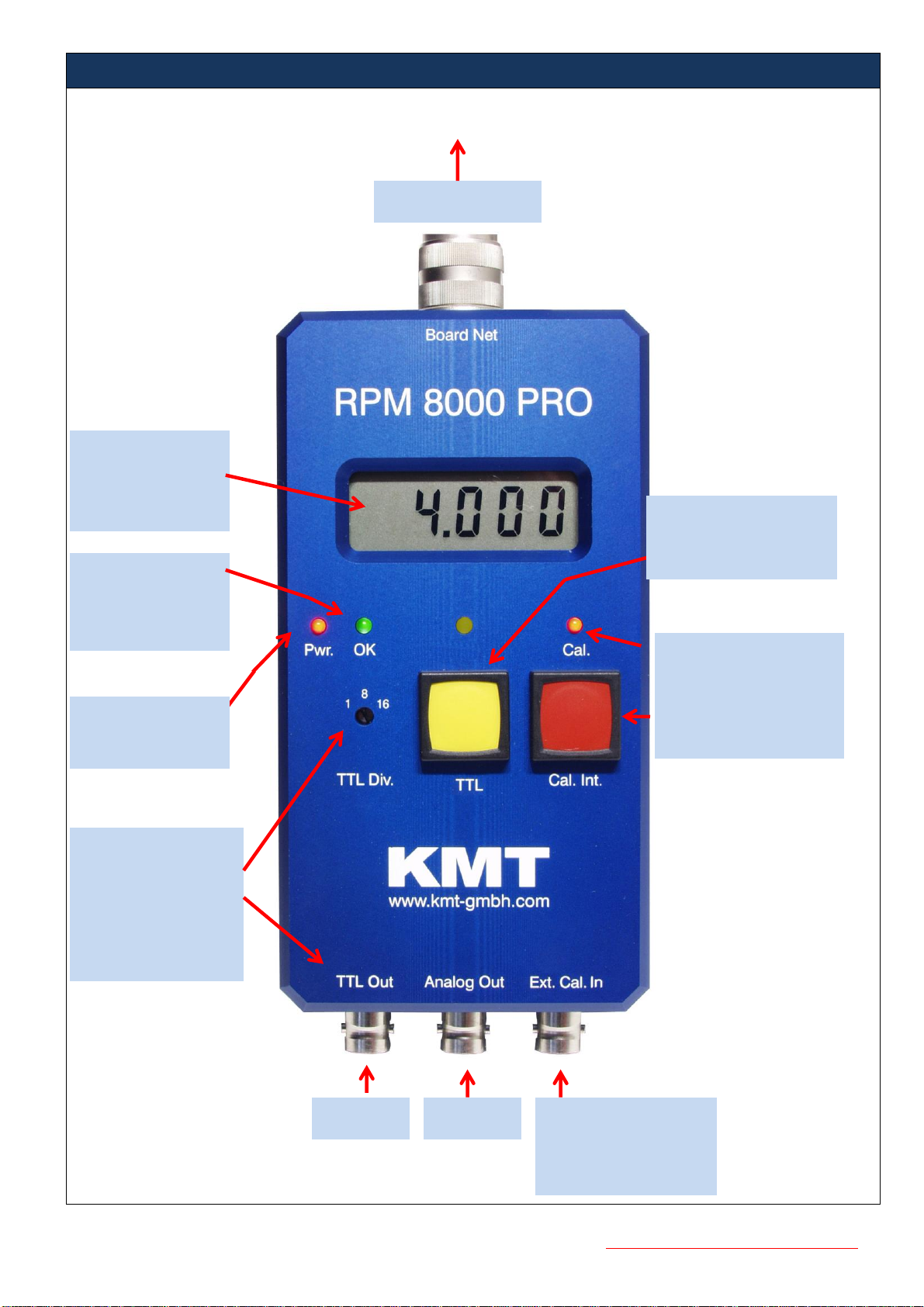
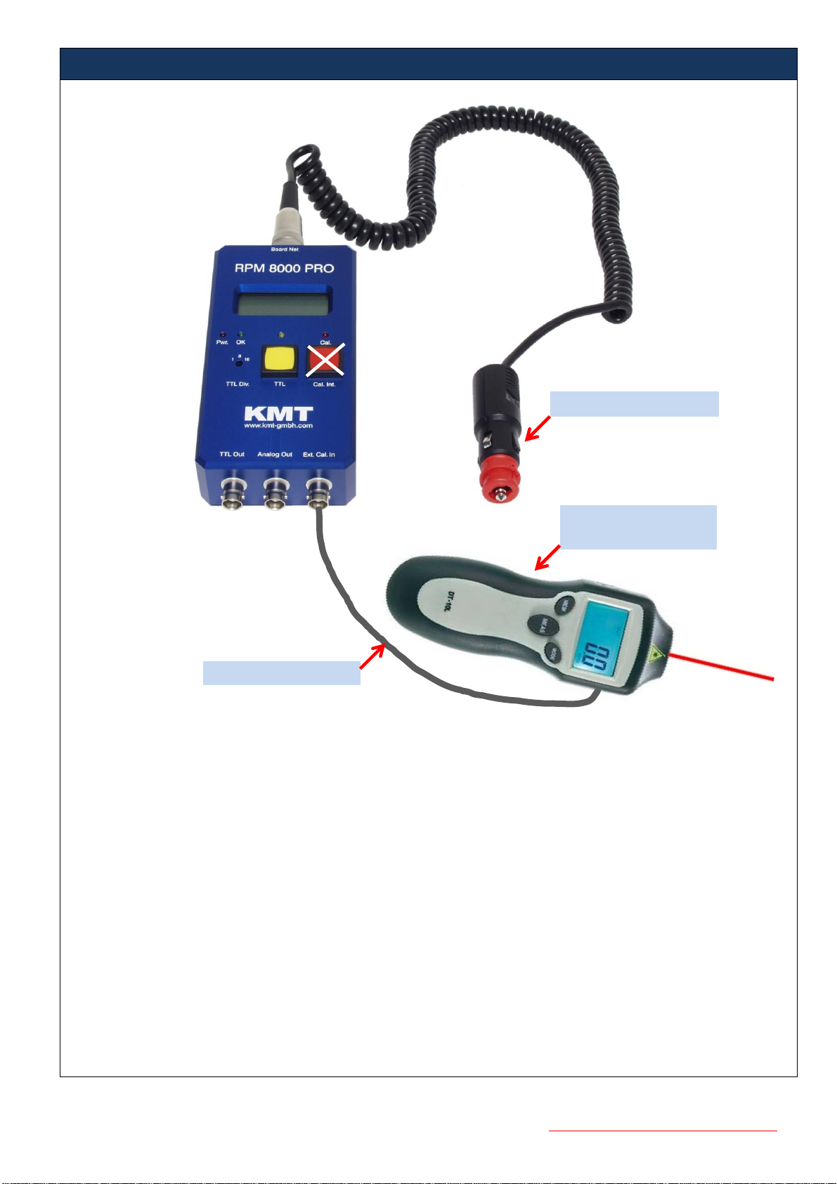
Start the engine, connect the coiled cable to the "Board Net" socket and plug the other end into the cigarette-lighter socket in the
vehicle. Make sure that the red "Power" LED on the RPM-8000PRO is illuminated.
After a short delay the device will detect the engine speed signal. Successful synchronization is signaled by the green "O.K."
LED on the RPM-8000PRO. The device is now in the ready state and all measuring signals are available at the output. If
synchronization has not taken place after a few seconds, this means that strong noise signals from vehicle loads have been
superimposed on the residual ripple from the vehicle electrical distribution system. In which case briefly press the accelerator and
synchronization will be achieved after returning to no-load speed.
You can now carry out the first tests by increasing and reducing the engine speed in the idling state and by monitoring the LCD
display and the voltage at the analog output. If the voltage tracks the engine speed synchronously, the device is functioning
properly on your vehicle.
Trouble shooting:
The use of cigarette-lighter sockets in the rear seating area or in the car trunk in some vehicles can cause additional
interference noise to be injected into the long line routes. You should therefore repeat the test at the socket on the
dashboard or on the driver's console.
A loss of synchronization may occur when the engine speed drops. In this case the vehicle electrical supply briefly switches
to battery-backup mode, as the high Faraday capacity of the battery is not able to decay quickly enough. To eliminate this
effect, switch on additional resistive loads (lights, window heater, etc.).
Some diesel engines in higher-class cars are equipped with overrunning alternators. In cases of extremely high
decelerations this may cause a short-time rotational speed difference between engine and alternator. This is important to
know, because the RPM-8000-PRO actually measures the number of revolutions per minute of the alternator.
If the RPM-8000-PRO is operated from the vehicle electrical distribution system while the engine is off and the ignition is on,
it may synchronize with arbitrary noise signals from the vehicle electrical distribution system, the reference signal from the
residual ripple is not available. In this case the green "O.K." LED is energized before the engine is started, and the system
must be "reset" by removing the connector from the cigarette-lighter socket for a short period. The same applies if the
engine is stopped and the green "O.K." LED does not go out.
On some luxury cars the RPM-8000-PRO may not work when plugged into the cigarette lighter socket. This is caused by
interference noise induced in the cable looms. The interference noise is generated by the considerable amount of electronic
hardware in these models and is within the synchronization spectrum of our RPM-8000-PRO. To avoid this problem,
connect the device via the supplied adapter cable to the battery or to a plus terminal nearest the battery. Make sure the
polarity of the adapter cable is correct
Should none of the abovemeasures prove successful, please contact us at: Mr. Plaksin plaksin@kmt-gmbh.com

Version 2012-10 10 Technical Data are subject to change without notice!
Technical details:
Supply voltage 12-42 V
Power consumption 80 mA maximum
Analog output: adjustable (Plug-in bride) 0.5 V, 1 V or 2 V per 1000 rev/min (Standard 1V)
max. delay 70 ms
accuracy > +/- 0.5% for petrol and +/- 1.5% for Diesel engines.
output impedance 2 ohm 10 mA
Digital output: frequency range approximately 500 Hz –10 kHz
set with frequency divider 1/1; 1/8; 1/16
TTL level 0 and 4 V
output impedance 130 ohm
Max. delay 0.1 –2 ms
jitter 0.1 –1 %
Synchronization
frequency range 800 Hz -2 kHz
Synchronization time 1 –2 seconds
Calibration: internal: based on 2000 rev/min indicated on tachometer
in vehicle.
external: with laser (RPM-LASER-CAL) and reflector tag on crankshaft.
Displays: LCD screen 4 ½ position for engine speed-frequency or
conversion factor frequency/engine speed
LED red Power
LED green Synchronization OK
LED yellow Number of pulses per revolution
LED red Calibration OK
Rotary switch: frequency divider 1/1, 1/8 or 1/16 (TTL Div) for TTL out
Red button: start internal calibration
Yellow button: show the number of pulses per revolution is indicated by pressing the yellow TTL button,
independently of the digital output divider (TTL Div).
Connectors: BNC for TTL output
BNC for analog output
BNC for external calibration input
3 pole Tuchel for connecting to vehicle electrical distribution system through cable
with connector for cigarette lighter
Dimensions: 150 x 75 x 40mm
Weight: 450g without connection cable
Material: anodized aluminum
Operating temperature: -5°C to +70°C
Storage temperature: -20 to +80°C
Humidity: 20 –80%
Vibrations: 5g military standard 810C curve C
shock in all directions 100 g

Version 2012-10 11 Technical Data are subject to change without notice!
KMT - Kraus Messtechnik GmbH
Gewerbering 9, D-83624 Otterfing, Germany, 08024-48737, Fax. 08024-5532
Home Page http://www.kmt-gmbh.com, Email: info@kmt-gmbh.com
R
RP
PM
M8
80
00
00
0P
PR
RO
O
T
Te
es
st
t
s
si
ig
gn
na
al
l
o
ou
ut
tp
pu
ut
t
Connection:
Test cable (Mini-Lemo 2-pol. to BNC)
You can use the same cable what delivered with LASER-CAL
Test Point

Version 2012-10 12 Technical Data are subject to change without notice!
Signal measure at 1300 RPM - Direct connection on car Battery via adaptor
0.5V/DIV
Time 0.5ms/DIV
Connection direct on battery: Less noise,
Signal is very good and RPM8000PRO works!!
Value 500mV/DIV-0.5ms/DIV - about 2000Hz
(Signal must be >200mV)

Version 2012-10 13 Technical Data are subject to change without notice!
Signal measure at 1300 RPM - connection on car cigarette lighter
More noise, but Signal is still
OK and RPM8000PRO works!!
0.5V/DI
V
Time 0.2ms/DIV
0.5V/DIV
Time 0.5ms/DIV
Table of contents
Other KMT Measuring Instrument manuals
Popular Measuring Instrument manuals by other brands

Fieldpiece
Fieldpiece Job Link SC480 Operator's manual

Endress+Hauser
Endress+Hauser Proline Promass 80 operating instructions

Elenco Electronics
Elenco Electronics XK-700-SEMI Assembly and instruction manual

Extech Instruments
Extech Instruments SL510 user manual

Sibelmed
Sibelmed DATOSPIR TOUCH EASY - F user manual

Anritsu
Anritsu MS2830A Operation manual