NOTICE DE MONTAGE
Support escamotable pour appareil
électroménager
Pièces incluses:
A. Mécanisme gauche
B. Mécanisme droit
C. 22 vis à tête bombée cruciformes
#8 x 1/2 in.
D. Plate-forme d’érable (en option) :
Comprend 1 paquet de vis
Outils nécessaires
•Tournevis cruciforme
•Perceuse avec mèche de 1,5 mm (1/16 in.)
pour le perçage d'avant-trous
•Crayon
•Mètre en ruban
Modèles
•Mécanisme : HAL 20
En option :
•Plate-forme d’érable 34,39 cm
(13.5 in.) WAL 13.5
•Plate-forme d’érable 41,91 cm
(16.5 in.) WAL 16.5
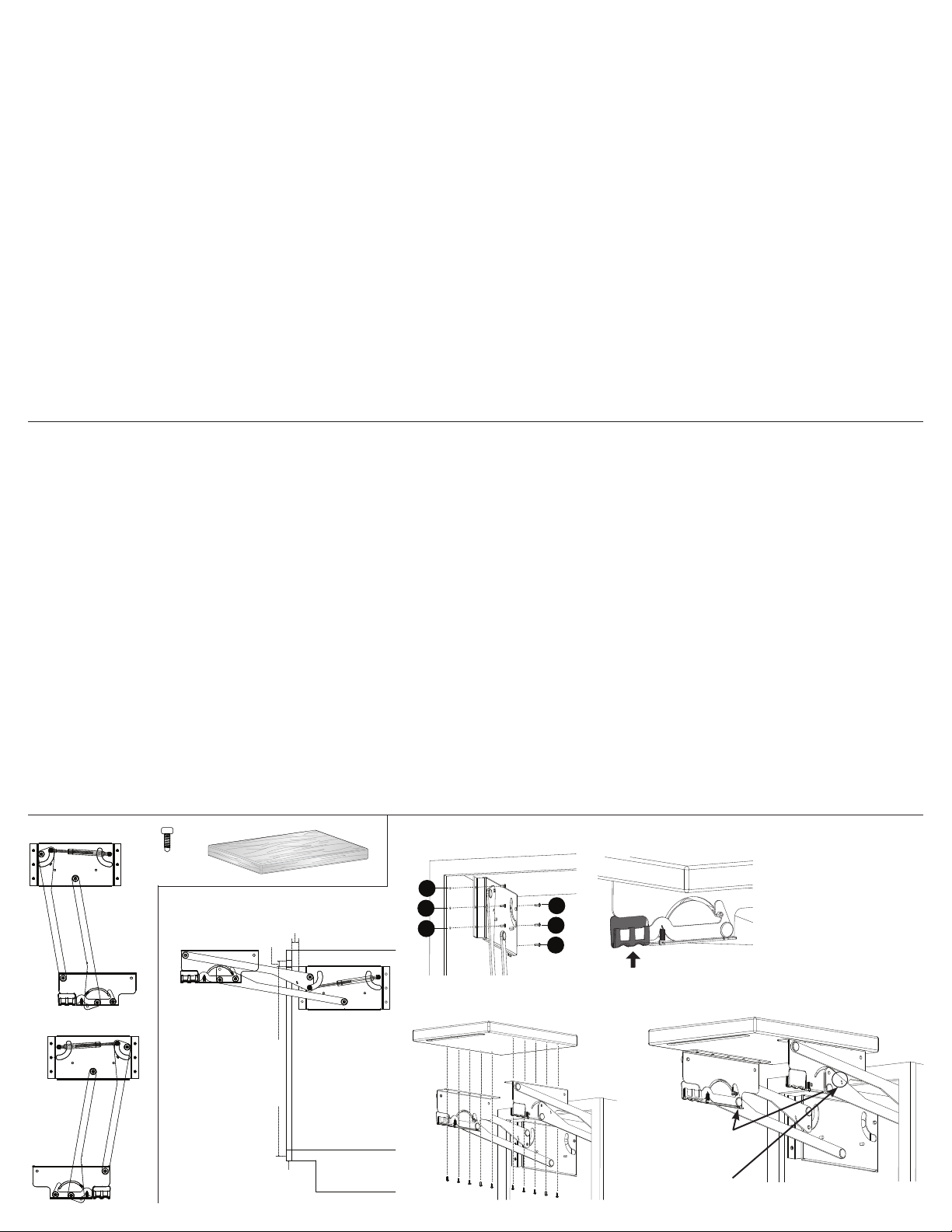
Étape 1
Inspecter toutes les pièces et lire toutes les
instructions avant de procéder à l'assemblage
et à l'installation.
Étape 2
Placer la partie gauche du mécanisme contre
la paroi intérieure de l’armoire (Figure 1), le
bord avant du mécanisme étant en retrait
de 12.7 mm (1/2 in.) par rapport au bord de
l’ouverture ou cadre avant de l’armoire et
le bord supérieur du mécanisme étant 12.7
mm en dessous de l’ouverture de l’armoire.
Marquer l'emplacement des 6 trous de
montage d'un repère au crayon.
Remarque: Les armoires traditionnelles avec
cadre peuvent requérir l’installation de blocs
de support en bois derrière le cadre afin de
garantir la sécurité de la fixation des bras de
relevage sur les côtés de l'armoire.
Étape 3
À l'aide de la mèche de 1.5 mm (1/16 in.),
percer des avant-trous aux emplacements
marqués pour y visser les vis de montage. Fixer
le mécanisme de bras de relevage à l’aide
de 6 des vis cruciformes à tête bombé (#8 x
1/2 in.), à commencer par l’emplacement no.
1 et en procédant jusqu’à l’emplacement no
4 (Figure 2). Puis abaisser le bras de relevage
pour accéder aux emplacements no 5 et no.
6 et y visser 2 autres vis.
Étape 4
Répéter les étapes 2 et 3 pour la partie droite
du mécanisme, en s’assurant que les supports
de montage des bras de relevage sont de
niveau et parallèles.
Étape 5
Relever les deux mécanismes en position
ouverte. Utiliser soit la plate-forme d’érable
en option ou une plate-forme personnalisée;
centrer la plate-forme sur les supports de
montage et la fixer avec 10 vis (Figure 3).
Étape 6
Libérer les leviers de verrouillage (Figure
4) et abaisser le mécanisme de support
escamotable pour appareil électroménager
dans l’armoire afin de vérifier son
encombrement.
Optionnel
Pour régler la hauteur en position déployée,
déplacer les broches de réglage (à gauche et
à droite) dans l'un des deux trous de réglage
(Figure 5). Plate-forme standard: la position
première des broches place la plate-forme
approximativement au niveau du plan de
travail. L'autre position place la plateforme 6
cm (2-3/8") au dessous du comptoir.
NOTER
Le classement maximum de chargement est
30 livres.
INSTRUCCIONES DE INSTALACIÓN
Ascensor para aparatos
Piezas Incluidas
A. Mecanismo izquierdo
B. Mecanismo derecho
C. (22) Tornillos Phillips #8 x 13.0mm.
D. Plataforma de arce (opcional):
Incluye un paquete de tornillos
Herramientas necesarias
•Destornillador Phillips
•Taladro con broca de 1.5 mm. para taladrar
agujeros pilotos
•Lápiz
•Cinta métrica
Para el armado de productos
•Mecanismo: HAL 20
Opcional:
•Plataforma de arce de 34.3 cm.: WAL 13.5
•Plataforma de arce de 41.9 cm.: WAL 16.5
Paso 1
Inspeccione todas las piezas y lea todas
las instrucciones antes de comenzar con el
armado y la instalación.
Paso 2
Coloque el lado izquierdo del mecanismo
a lo largo de la pared interior del gabinete
(Figura 1), con el borde frontal del mecanismo
posicionado a 1.3 cm. afuera del borde de la
abertura del gabinete o el armazón frontal y el
borde superior del mecanismo, a 1.3 cm. por
debajo de la abertura del gabinete. Marque
cada una de las posiciones de los 6 agujeros
con un lápiz.
Nota: Es posible que los gabinetes de estilo
armazón frontal requieran la instalación de
bloques de apoyo de madera detrás del
armazón frontal para permitir que se adhiera
fuertemente a los brazos de alza al lado del
gabinete.
Paso 3
Usando la broca de tornillo de 1.6mm,
taladre los agujeros de piloto para introducir
los tornillos de montaje en las posiciones ya
marcadas. Sujete el mecanismo del brazo de
alza en su lugar al usar 6 de los tornillos Phillips
#8 x 13.0mm., comenzando con la posición de
agujero #1 y siga hasta la posición #4 (Figura
2). Luego baje el brazo para obtener acceso
a y para sujetar las posiciones de los agujeros
#5 y #6.
Paso 4
Repita los pasos 2 y 3 del lado derecho del
mecanismo, asegurándose que la posición de
las abrazaderas de los brazos de alza estén
niveladas y paralelas la una con la otra.
Paso 5
Levante ambos mecanismos a la posición
abierta. Usando la plataforma opcional de
arce o una plataforma hecha a la medida,
centre la plataforma en las abrazaderas de
montaje y conecte usando 10 tornillos
(Figura 3).
Paso 6
Levante sobre las palancas de liberación
(Figura 4) y baje el ascensor de aparatos al
gabinete, verificando que esté bien ajustado y
que tenga suficiente despeje.
Opcional
Para acomodar la altura de una posición
abierta, podrá hacer ajustes al trasladar
ambas clavijas de ajuste (la izquierda tanto
como la derecha) a una de dos posiciones
de agujeros disponibles (Figura 5). Con
la plataforma ordinaria, si usa la posición
primera de clavija, la plataforma quedará
aproximadamente a nivel del mostrado. La
otra posición coloca la plataforma 6 cm (2-3/8")
debajo de la encimera.
NOTE
La calificación que máxima de carga
es 30 lbs.
A. D.
B.
C. Figure 2 / Figura 2
2
3
4
1
5
6
Figure 3 / Figura 3
Figure 4 / Figura 4
Figure 5 / Figura 5
Broches de réglage
Clavijas de ajuste
Trous de réglage
Posiciones de los gujeros
Figure 1 / Figura 1
Cabinet
Opening
Face
Frame
1/2" 1/2"
Ouverture de
l'armoire
Abertura del
gabinete
Cadre de l’armoire
Armazón frontal RN-272EFS-D-0511
©2011 Knape & Vogt.
Reservados todos los
derechos. Hecho en
China. El Knape y Vogt®
reservan el derecho de
cambiar especicaciones
sin el aviso.
©2011 Knape & Vogt.
Tous droits réservés.
Fabriqué en Chine.
Knape et Vogt®réservent
le droit de changer des
spécications
sans préavis.


