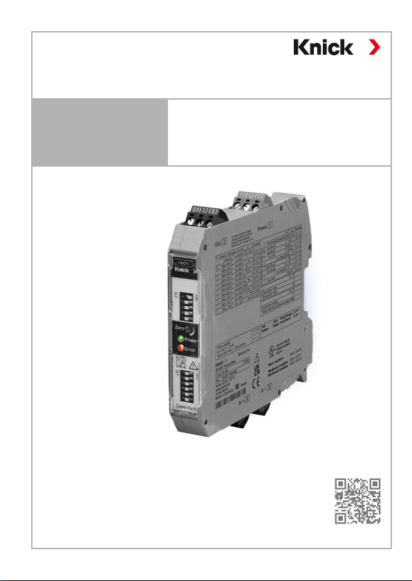
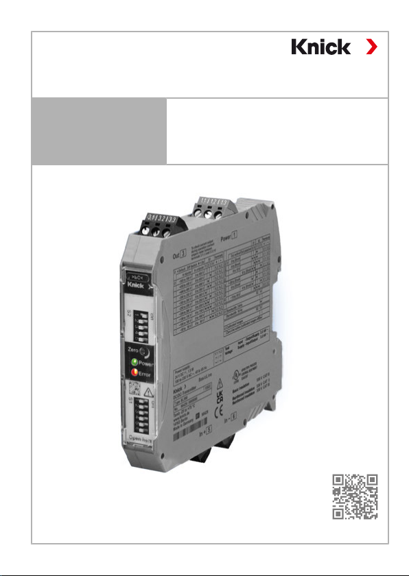
Knick BL590 User manual

User Manual BL590/BL591
Universal Isolated Signal Conditioner
www.knick.de
Read before installation.
Keep for future use.
English....................... 3
Deutsch..................... 33
Français ..................... 65

Table of Contents
English.................................................................................................................... 3
Deutsch.................................................................................................................. 33
Français .................................................................................................................. 65

User Manual BL590/BL591
Universal Isolated Signal Conditioner
www.knick.de
Read before installation.
Keep for future use.
Copyright 2021 • Subject to change
Version: 1 • Published on July 14, 2021

BL590/BL591
4
Supplemental Directives
These supplemental directives explain how safety information is
laid out in this document and what content it covers.
Safety Chapter
This document's safety chapter is designed to give the reader a
basic understanding of safety. It illustrates general hazards and
gives strategies on how to avoid them.
Warnings
This document uses the following warnings to indicate hazardous
situations:
Sym-
bol
Category Meaning Remark
WARN-
ING
Designates a situation that can lead to
death or serious (irreversible) injury.
The warnings
contain informa-
tion on how to
avoid the haz-
ard.
CAU-
TION
Designates a situation that can lead to
slight or moderate (reversible) injury.
None NOTICE Designates a situation that can lead to
property or environmental damage.

BL590/BL591
5
Table of Contents
1 Safety.................................................................................... 7
1.1 Intended Use ................................................................................ 7
1.2 Residual Risks ............................................................................... 9
1.3 Electrostatic Discharge ............................................................. 9
2 Product................................................................................. 10
2.1 Package Contents and Product Identification.................. 10
2.1.1 Nameplates.................................................................. 10
2.2 Symbols and Markings.............................................................. 11
2.3 Functional Description.............................................................. 12
3 Commissioning .................................................................... 14
3.1 Mounting and Electrical Connection................................... 14
3.2 Terminal Assignment and Dimensions ............................... 15
3.3 Input Ranges................................................................................. 16
3.4 Output Ranges............................................................................. 17
4 Installation ........................................................................... 18
4.1 Input Wiring .................................................................................. 18
4.2 Output Wiring .............................................................................. 19
5 Operation ............................................................................. 23
5.1 Control Elements (Head Plate) ............................................... 23
5.2 Test Jacks........................................................................................ 24
5.3 Characteristic Curves ................................................................. 25
6 Troubleshooting .................................................................. 26
7 Maintenance ........................................................................ 27
8 Decommissioning................................................................ 28
8.1 Returns............................................................................................ 28
8.2 Disposal .......................................................................................... 28

BL590/BL591
6
9 Specifications....................................................................... 29
9.1 Voltage Input Data...................................................................... 29
9.2 Output Data .................................................................................. 29
9.3 Transmission Behavior .............................................................. 30
9.4 Power Supply (Power) ............................................................... 30
9.5 Isolation.......................................................................................... 31
9.6 Conformity..................................................................................... 31
9.7 Product ........................................................................................... 32
9.8 Ambient Conditions................................................................... 32

BL590/BL591
7
1 Safety
This document contains important instructions for the use of the
product. Always follow all instructions and operate the product
with caution. If you have any questions, please contact Knick
Elektronische Messgeräte GmbH & Co. KG (sometimes hereafter
referred to as "Knick") using the information provided on the back
page of this document.
This user manual is intended for use by planners, builders, and
operators of electrical equipment. This group of persons is referred
to below as users.
Personnel Requirements
The user must ensure that employees who use or otherwise handle
the product are adequately trained and have been properly
instructed, in particular with regard to the hazards and rules set out
in this document.
1.1 Intended Use
The BL590 / BL591 (also referred to below as the “product”) are
universal isolated signal conditioners for galvanic 3-port isolation
between the input, output, and power supply. The product is used
for the direct measurement of voltage and the measurement of
current via a shunt resistor. Calibrated range selection is performed
using DIP switches.
• BL590 for voltage measurement up to (±)50…(±)500V DC
• BL591 for current measurement via a shunt resistor with a volt-
age input (DC) of (±)30…
(±)1000mVDC

BL590/BL591
8
The input signal is reproduced at the output as a 0…20mA,
4…
20mA, or 0…10V standard signal, or as a bipolar -20…20mA or
-10…
10V output signal. The zero point can be adjusted using a
connectable potentiometer. This is used to compensate for offset
errors in the system. Zero point adjustment of the product is not re-
quired. The zero point is factory-adjusted for each measuring
range.
Applications
• Inverters, rectifiers, and frequency converters
• Electric drives and generators
• Power supply for welding units
• Solar and wind power farms
• Electrical power storage
• Monitoring charging processes and states
• Monitoring and controlling DC current supply units
Install the product in an enclosed, lockable, and fire-protected
enclosure or distribution box. ➜Installation, p. 18
Improper Use
Care must always be taken when installing, operating, maintaining,
troubleshooting, or otherwise handling the product. The product
may only be operated within the scope of the intended use set out
here and within the limits specified in the Specifications chapter.
The user is responsible for compliance with this requirement. Any
use of the product beyond the scope specified here is prohibited
and may result in serious injury to persons, death, and property
damage.

BL590/BL591
9
1.2 Residual Risks
The product has been developed and manufactured in accordance
with generally accepted safety rules and regulations, as well as an
internal risk assessment. Despite the foregoing, the product may
among others bear the following risks:
Shock potential.
For applications with high working voltages, take measures to pre-
vent accidental contact and ensure sufficient clearance or insula-
tion between adjacent devices.
The product must be operated within an enclosure. Do not touch
the product during operation. Dangerously high voltages may be
present on accessible parts of the product.
Isolation Failure
Despite meticulous engineering and 100% testing of the isolation
after manufacture, the isolation barriers, like any electrotechnical
component, may fail accidentally or due to overload. In the event
of isolation failure, dangerously high voltages may be conducted
from the input to the output and power supply terminals and may
be present there and on the connected equipment. This may result
in serious injury, death, and property damage.
1.3 Electrostatic Discharge
Take measures to prevent electrostatic discharge (ESD) when
installing or adjusting the product.

BL590/BL591
10
2 Product
2.1 Package Contents and Product Identification
• Product BL590 / BL591
• Sales packaging (brown folding cardboard box with window
over device nameplates)
• User manual in three languages (German, English, French)
2.1.1 Nameplates
Illustrative example
1 2
3 4 5 6 7
8
910
11
12
13
1 Power supply 6 UKCA mark
2 Test voltage 7 UL mark
3 Name of manufacturer 8 Isolation
4 Product name 9 CE mark
5 Special conditions and the
product’s possible danger
points. Read the user manual,
observe the specifications, and
follow the instructions in the
Safety chapter.
10 Manufacturer’s website and
address with barcode
11 Permissible ambient
temperature
12 Product number/serial number
13 Model designation

BL590/BL591
11
2.2 Symbols and Markings
Safety Alert Symbols on the BL590 / BL591 and in the User
Manual
Electric shock hazard! DO NOT touch electrical components!
Special conditions and the product’s possible danger points. Read the
user manual, observe the specifications, and follow the instructions in
the Safety chapter.
Markings
Attaching the CE marking to the product means that the product
satisfies the applicable requirements specified in the European Union
harmonization legislation.
UL Listed: Combined UL mark for Canada and the United States
UK Conformity Assessed: Conformity mark for the United Kingdom of
Great Britain and Northern Ireland

BL590/BL591
12
2.3 Functional Description
The input signal is converted into a pulse-width modulated signal
and fed into the primary side of a transformer. On the secondary
side, the pulse-width signal is converted back into load-indepen-
dent current or impressed voltage.
The 3-port isolation helps to ensure undistorted transmission of the
measuring signals. Protective separation thanks to reinforced
insulation in accordance with EN 61140 protects persons from
electric shock. The basic insulation protects the equipment.
3-port isolation of the 3 circuits: inputs, outputs, and power
supply
1
2
3
1 Inputs 3 Power supply
2 Outputs

BL590/BL591
13
Block Diagram
1 2
3
1 Input 3 Power supply (reverse polarity
protected; polarity is random
for supply with direct voltage)
2 Output

BL590/BL591
14
3 Commissioning
3.1 Mounting and Electrical Connection
WARNING! Shock potential. For applications with high work-
ing voltages, take measures to prevent accidental contact and en-
sure sufficient clearance or insulation between adjacent devices.
Do not connect the product power supply or apply measuring volt-
age until it has been professionally installed.
Installation Conditions
Install the product in a suitable housing (enclosure/distribution
box) that ensures pollution degree PD 2 or higher and protects
from mechanical impact. The housing may only be opened using a
tool (wrench).
The devices are snapped onto mounting rails in accordance with
EN60715 with a width of 35mm. They are secured on the side
using suitable end brackets.
Conductor cross-section: 0.2mm2
…2.5mm2 (AWG24-12).
NOTICE! Only use copper cables that are process temperature
resistant to at least 75°C.
CAUTION! Install a two-pole disconnect device between the
product and the mains.
Isolation
Applications with a working voltage in one of the circuits in excess
of the specified reinforced insulation and the possible contact of a
person with a different circuit require an additional protective mea-
sure in accordance with the relevant codes and standards for the
installation of electrical equipment (e.g., VDE 0100 and NEC), such
as:
• Extra insulation
• Protective connection or shielding
• Automatic disconnection from the power supply
• Current or voltage limiting device

BL590/BL591
15
3.2 Terminal Assignment and Dimensions
1.1 Power supply1) 5.1 Not used
1.2 Power supply1) 5.2 Positive input
1.3 Not used 5.3 Not used
3.1 Current output (passive/ac-
tive)2)
6.1 Not used
3.2 GND output 6.2 Negative input
3.3 Voltage output2) 6.3 Not used
1) Polarity is random for supply with direct voltage
2) The signal outputs are open-circuit-proof or short-circuit-proof

BL590/BL591
16
3.3 Input Ranges
BL590
No. Bipolar input
range
Unipolar input
range
Switch
S1: 1
…
4
Input
resistance
Input
terminals
11) –500…500V 0…500V 0000 2MΩ 5.2 / 6.2
2-450…450V 0…450V 0010 2MΩ 5.2 / 6.2
3-400…400V 0…400V 0100 2MΩ 5.2 / 6.2
4-350…350V 0…350V 0110 2MΩ 5.2 / 6.2
5-300…300V 0…300V 1000 2MΩ 5.2 / 6.2
6-250…250V 0…250V 1010 2MΩ 5.2 / 6.2
7-200…200V 0…200V 1100 2MΩ 5.2 / 6.2
8-150…150V 0…150V 1110 2MΩ 5.2 / 6.2
9-100…100V 0…100V 0001 2MΩ 5.2 / 6.2
10 -50…50V 0…50V 0011 2MΩ 5.2 / 6.2
BL591
No. Bipolar input
range
Unipolar in-
put range
Switch
S1: 1
…
4
Input
resistance
Input
terminals
11) –1000…1000mV 0…1000mV 0000 10kΩ 5.2 / 6.2
2-300…300mV 0…300mV 0010 10kΩ 5.2 / 6.2
3-150…150mV 0…150mV 0100 10kΩ 5.2 / 6.2
4-100…100mV 0…100mV 0110 10kΩ 5.2 / 6.2
5-90…90mV 0…90mV 1000 10kΩ 5.2 / 6.2
6-75…75mV 0…75mV 1010 10kΩ 5.2 / 6.2
7-60…60mV 0…60mV 1100 10kΩ 5.2 / 6.2
8-50…50mV 0…50mV 1110 10kΩ 5.2 / 6.2
9-45…100mV 0…45mV 0001 10kΩ 5.2 / 6.2
10 -30…30mV 0…30mV 0011 10kΩ 5.2 / 6.2
1) Factory setting

BL590/BL591
17
3.4 Output Ranges
BL590 / BL591
No. Input Active out-
put
Passive
output
S1:
5
…
6
S2: 1
…
3Output termi-
nals
1 Unipolar 0-20mA 00 100 3.1 / 3.2
2 Unipolar 4…20mA 11 100 3.1 / 3.2
3 Unipolar 0…10V 01 110 3.3 / 3.2
4 Unipolar 4…20mA 11 001 3.1 / 3.2
5 Bipolar -20…20mA 00 100 3.1 / 3.2
6 Bipolar 4…20mA 10 100 3.1 / 3.2
7 Bipolar 4…20mA 10 001 3.1 / 3.2
8 Bipolar -10…10V 01 110 3.3 / 3.2

BL590/BL591
18
4 Installation
4.1 Input Wiring
BL590 BL591
1
22
1
1 Terminal 2 Voltage source

BL590/BL591
19
4.2 Output Wiring
The current measurement shown here (3) is for verifying the out-
put current without opening the output circuit. Terminals 3.1 and
3.3 are the monitor output.
The monitor output can be used for non-disruptive testing of the
output current by temporarily connecting a multimeter (to the test
jacks), or permanently connecting an isolated display unit.
An interruption in the monitor output, e.g., due to an open circuit,
will not result in impairment or failure of the primary current out-
put.

BL590/BL591
20
Active Current Output with Optional Measurement
1
2
4
3
1 Test jack 3 Optional current measurement (only DC
currents can be correctly measured)
2 Terminal 4 Optional voltage measurement: V is used
to verify whether the connected load is
within the specified range. The voltage
must be ≤12V.
This manual suits for next models
1
Table of contents
Languages:
Other Knick Test Equipment manuals
Popular Test Equipment manuals by other brands

Rohde & Schwarz
Rohde & Schwarz R&S RTP-K28 user manual

Southwire
Southwire M400TP operating instructions

norbar
norbar PRO-TEST 40 Operator's handbook

Triplett
Triplett PairMaster 3240-22 instruction manual

Whirlwind
Whirlwind AESQbox manual

Ignition Interlock Devices
Ignition Interlock Devices BrAC Audit Lock-1 Instructions & user's manual