Ecom MA 400 User manual
MA 400
Bedienungsanleitung
Operating Instructions
Notice d‘utilisation
BAL MA 400.indd 1 28.11.2005 10:17:43 Uhr

15
Table of Contents
1. Introduction 16
1.1 Repairs 16
1.2 Safety Information 16
2. Overview 19
3. Getting Started 19
3.1. Battery Save Feature 19
3.2 HART™ Resistor Setup 20
4. Basic Operating Modes 20
4.1 Milliamp Source 21
4.2 Milliamp Simulation 22
4.3 Milliamp Measure 23
4.4 Milliamp Measure with Loop Power 23
4.5 Voltage Measure 24
5. Advanced Operating Modes 24
5.1 Auto Step/Ramp Mode 24
5.2. Percent Error Mode 25
5.3 Min/Max Datalogging 25
6. Maintenance 25
6.1 Battery Selection 25
6.2 Input Protection 25
6.3 Calibration 25
7. Specifications 26
8. Warranty and liability 27
BAL MA 400.indd 15 28.11.2005 10:17:55 Uhr

16
1. Introduction
The MA 400 is designed to be a complete 4 to 20mA current calibrator for both troubleshooting
and calibrating current loops. Very high accuracy combined with several unique features makes the
MA 400 an easy to use and highly flexible calibration tool.
The MA 400 can source, simulate (2-wire) or measure loop currents up to 24mA. It can also measure
process signal voltages up to 28VDC with the same 0.015% of reading accuracy. A digital knob user
interface combined with decade output control allows the user to make both large or small output
changes with ease.
Several unique functions such as the autostep/ramp modes allow the MA 400 to test valve
actuators for smoothness and proper operation. The MA 400 can also power two-wire transmitters
while simultaneously reading the resultant loop current. All readings are displayed in both milliamps
and % of span.
1.1 Repairs
Repair work is subject to the nationally valid regulations and directives. We therefore recommend that
such work be performed by ecom instruments GmbH, Germany, as all repairs must be examined to
ensure functional safety.
1.2 Safety information
These operating instructions contain information and safety regulations that must be followed to ensure
safe and reliable operation of the unit under the described conditions. Failure to follow the information
and instructions can have dangerous consequences or may contravene applicable regulations. Please
take the time to carefully read through the owner’s manual before you start using the unit. In the event
of any doubt or discrepancies (e.g. due to translation or printing errors), the German version of these
operating instructions shall govern.
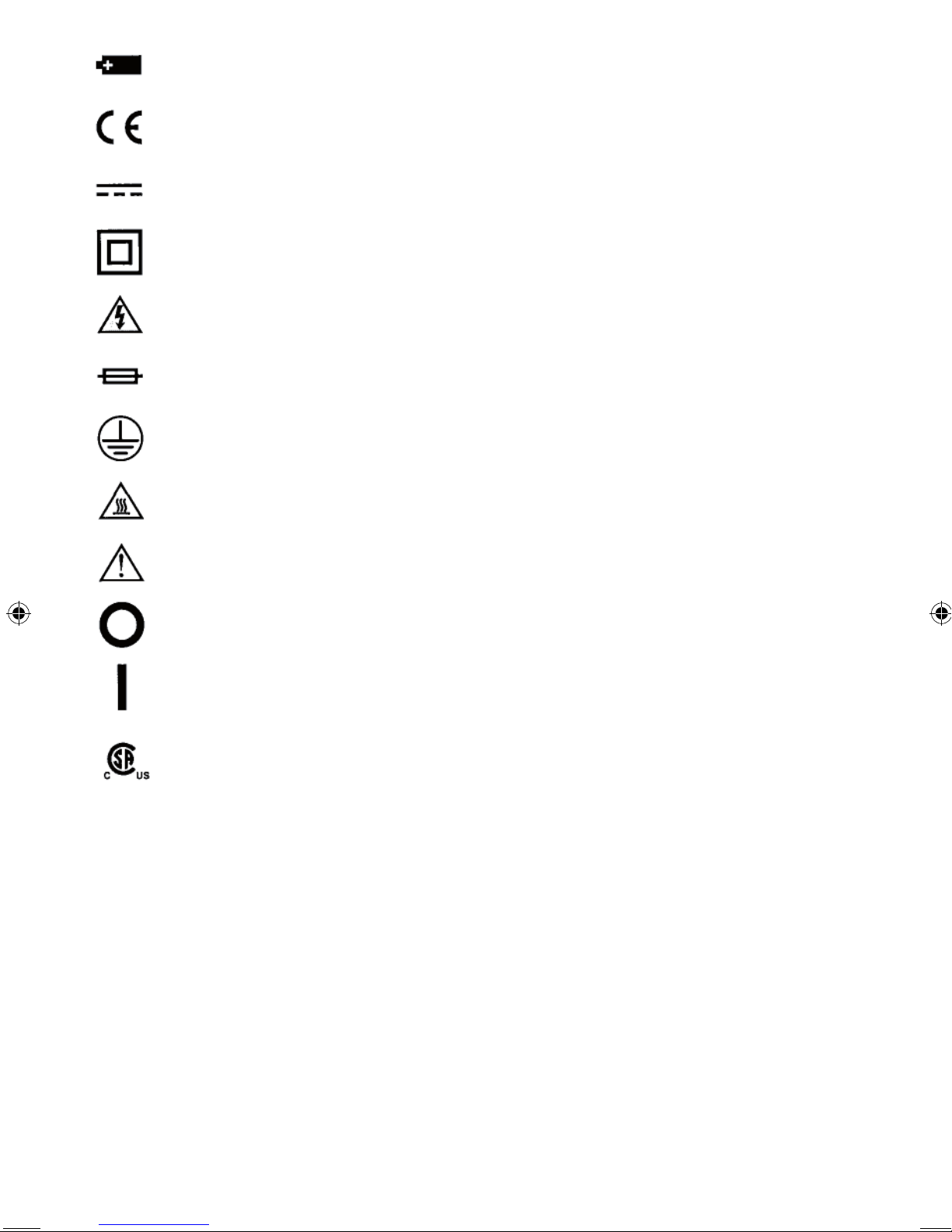
Symbols Used
The following table lists the International Electrical Symbols. Some or all of these symbols may be used
on the instrument or in this manual.
Symbol Description
AC (Alternating Current)
AC-DC
BAL MA 400.indd 16 28.11.2005 10:17:55 Uhr
17
Battery
CE Complies with European Union Directives
DC
Double Insulated
Electric Shock
Fuse
PE Ground
Hot Surface (Burn Hazard)
Read the User’s Manual (Important Information)
Off
On
Canadian Standards Association
The following definitions apply to the terms “Warning” and “Caution”.
- “Warning” identifies conditions and actions that may pose hazards to the user.
- “Caution” identifies conditions and actions that may damage the instrument being used.
Use the calibrator only as specified in this manual, otherwise injury and damage to the calibrator
may occur.
BAL MA 400.indd 17 28.11.2005 10:17:55 Uhr

18
m
Warning
To avoid possible electric shock or personal injury:
- Do not apply more than the rated voltage. See specifications for supported ranges.
- Follow all equipment safety procedures.
- Do not use the calibrator if it is damaged.
Before you use the calibrator, inspect the case. Look for cracks or missing plastic.
Pay particular attention to the insulation surrounding the connectors.
- Select the proper function and range for your measurement.
- Make sure the battery cover is closed and latched before you operate the calibrator.
- Remove test leads from the calibrator before you open the battery door.
- Inspect the test leads for damaged insulation or exposed metal.
- When using the probes, keep your fingers away from the probe contacts.
Keep your fingers behind the finger guards on the test leads.
- Do not use the calibrator if it operates abnormally.
Protection may be impaired. When in doubt, have the calibrator serviced.
- Do not operate the calibrator around explosive gas, vapor, or dust.
- Disconnect test leads before changing to another measure or source function.
- When servicing the calibrator, use only specified replacement parts.
- To avoid false readings, which could lead to possible electric shock or personal injury,
replace the battery as soon as the battery indicator appears.
m
Caution
To avoid possible damage to calibrator or to equipment under test:
- Use the proper jacks, function, and range for your measurement or sourcing application.
BAL MA 400.indd 18 28.11.2005 10:17:55 Uhr
19
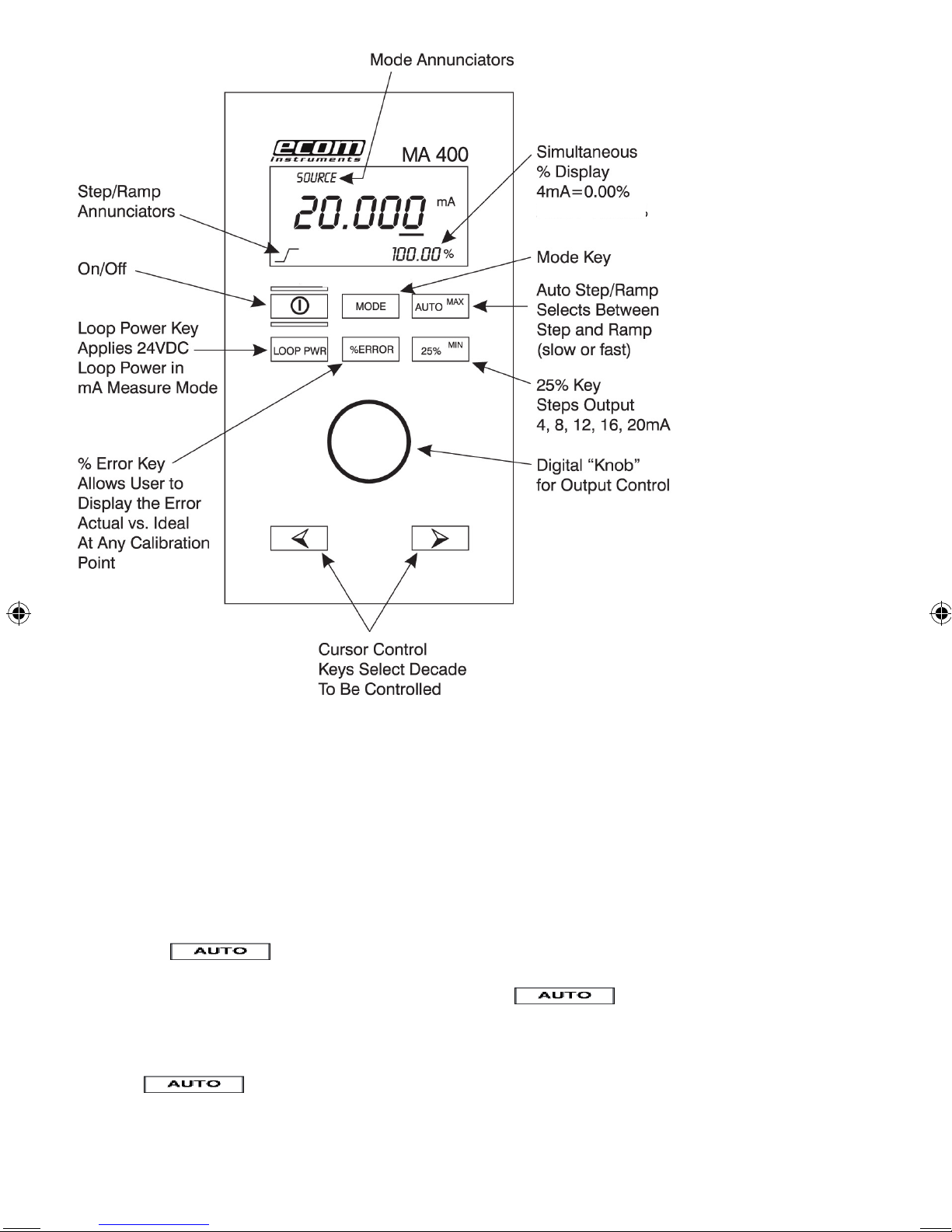
2. Overview
Figure 1
3. Getting Started
3.1 Battery Save Feature
After unpacking the MA 400, it should be ready for use. A 9 volt alkaline battery comes preinstalled.
The “Battery Save” feature is enabled and set to 30 minutes in case the unit is accidentally
turned on in transit. The battery save feature will turn off the MA 400 automatically if no keys are
pressed after 30 minutes. To change the length of time on the battery save feature or to disable it
completely perform the following steps during power up:
1) Turn off the MA 400.
2) Hold the key down firmly.
3) Turn on the MA 400.
4) After power up, wait about 1 second and release the key.
5) The display will now indicate the amount of time the battery save feature is set for
(off to 30 minutes).
6) Using the knob, set the desired time (off to 30 minutes).
7) Press again to store the value and return the unit to normal mode.
The stored value will remain in memory until changed by the operator.
BAL MA 400.indd 19 28.11.2005 10:17:57 Uhr
20mA = 100%
20
3.2 HART ™ Resistor Setup
The MA 400 incorporates an internal 250 ohm resistor to facilitate using a Rosemount 275
Communicator during calibration or installation of HART™ transmitters. The internal resistor takes the
place of the 250 ohm resistor normally installed during the use of the model 275 Communicator.
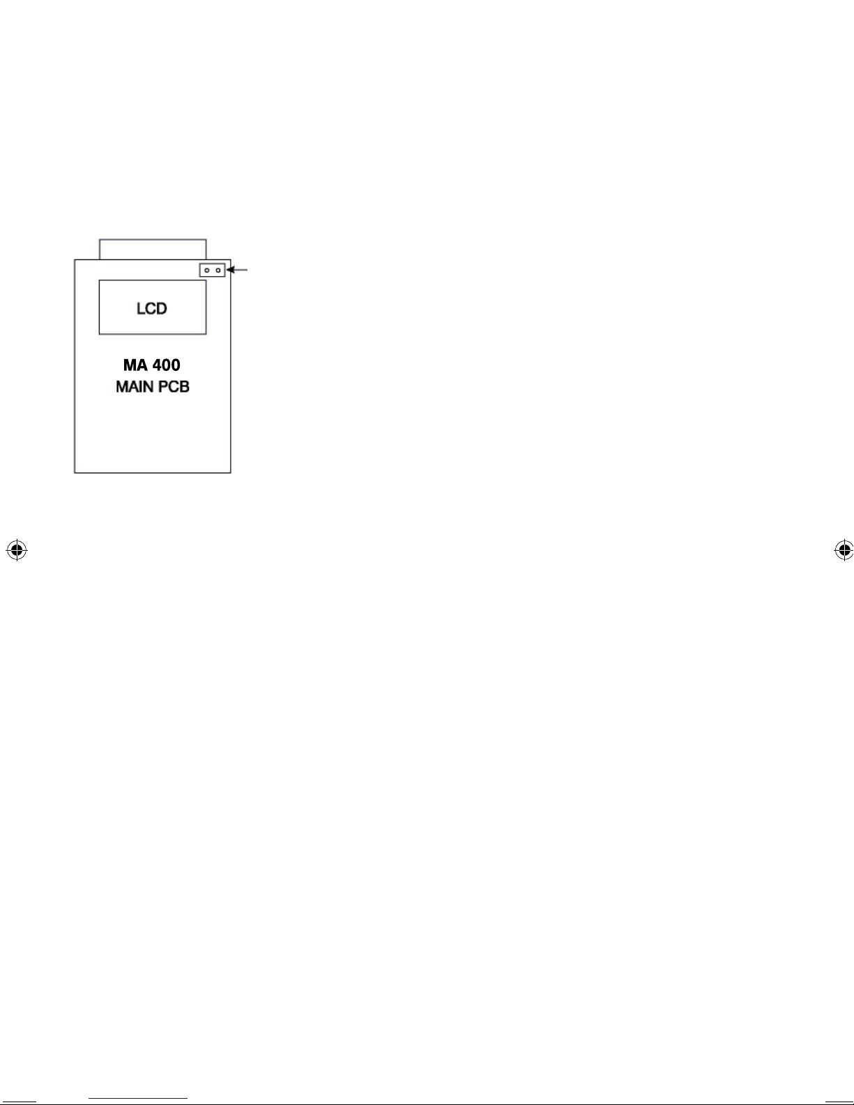
An internal jumper can be removed to enable this feature if desired. The unit is shipped with the jumper
in place. To remove the jumper open the case and refer to Figure 2 to locate the jumper, then pull off
the jumper to enable the resistor. The jumper can be stored outside of the unit or re-installed only
on one pin so that the circuit remains open.
-J8 (HART™ JUMPER)
Remove Jumper to Enable HART™ 250 Ohm Resistor
Figure 2
Note: When the 250 ohm resistor is enabled the load driving capability is reduced from 1200
ohms to 950 ohms. In most cases this should not be a problem when calibrating Non-HART™
compatible products.
4. Basic Operating Modes
The MA 400 offers 4 modes of milliamp operation and one voltage measure mode. The following
text and figures explain the various operating modes:
BAL MA 400.indd 20 28.11.2005 10:17:57 Uhr

21
4.1 Milliamp Source
Figure 3 shows a typical application where the MA 400 is sourcing 4 to 20 mA into a device
under test.
Figure 3 - Sourcing 4 to 20 mA
1) Turn on the MA 400. It will default to the mA source mode.
2) Connect the device to be calibrated.
Note: The loop must be closed for the MA 400 to source current. If an open loop occurs
“OL” will flash on the LCD indicating an overload or open condition.
3) The output can be adjusted to the desired value by using the knob interface and selecting
the decade to be adjusted.
4) The output can also be stepped in 4 mA steps (25%) using the key.
5) The auto step feature provides automated output changes. Refer to the Auto Modes
Section (5.1) of the manual for more information.
BAL MA 400.indd 21 28.11.2005 10:17:58 Uhr
22
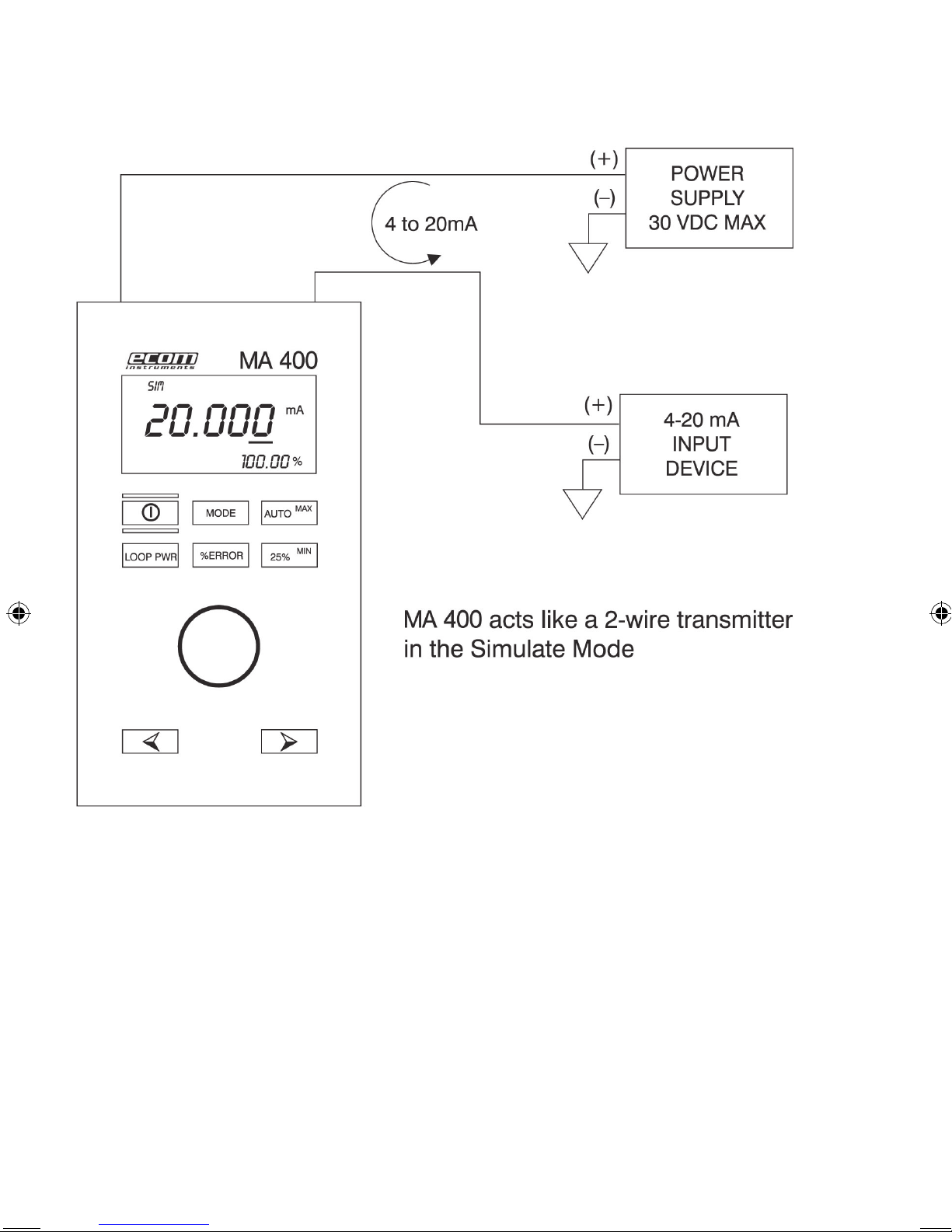
4.2 Milliamp Simulation
Figure 4 shows how to connect the MA 400 to act as a two-wire transmitter using an external
power supply. In this application the power for the loop comes from the external supply and
the MA 400 simply controls the current flow through the loop. The procedure for controlling
the output is the same as the milliamp source.
Figure 4 - Simulating 4 to 20 mA
BAL MA 400.indd 22 28.11.2005 10:17:59 Uhr

23
4.3 Milliamp Measure
Figure 5 shows how to connect the MA 400 to measure a 4-20 mA loop. In this application the
MA 400 is simply reading the loop current and displaying the current in mA on the main display.
The lower (smaller) display area is showing percentage relative to a 4 to 20 mA span.
4.4 Milliamp Measure with Loop Power
Again, Figure 5 shows the proper connections. But in this case the device under test is a twowire
transmitter that requires an external power supply to generate an output current. In this
application the MA 400 will supply 24 volts to the loop while simultaneously measuring the resultant
loop current. To turn on the loop power supply press the key while in the mA measure mode.
Figure 5 - Measuring 4 to 20 mA
NOTE: The loop power mode can only be enabled while in the mA measure mode.
BAL MA 400.indd 23 28.11.2005 10:18:01 Uhr
24
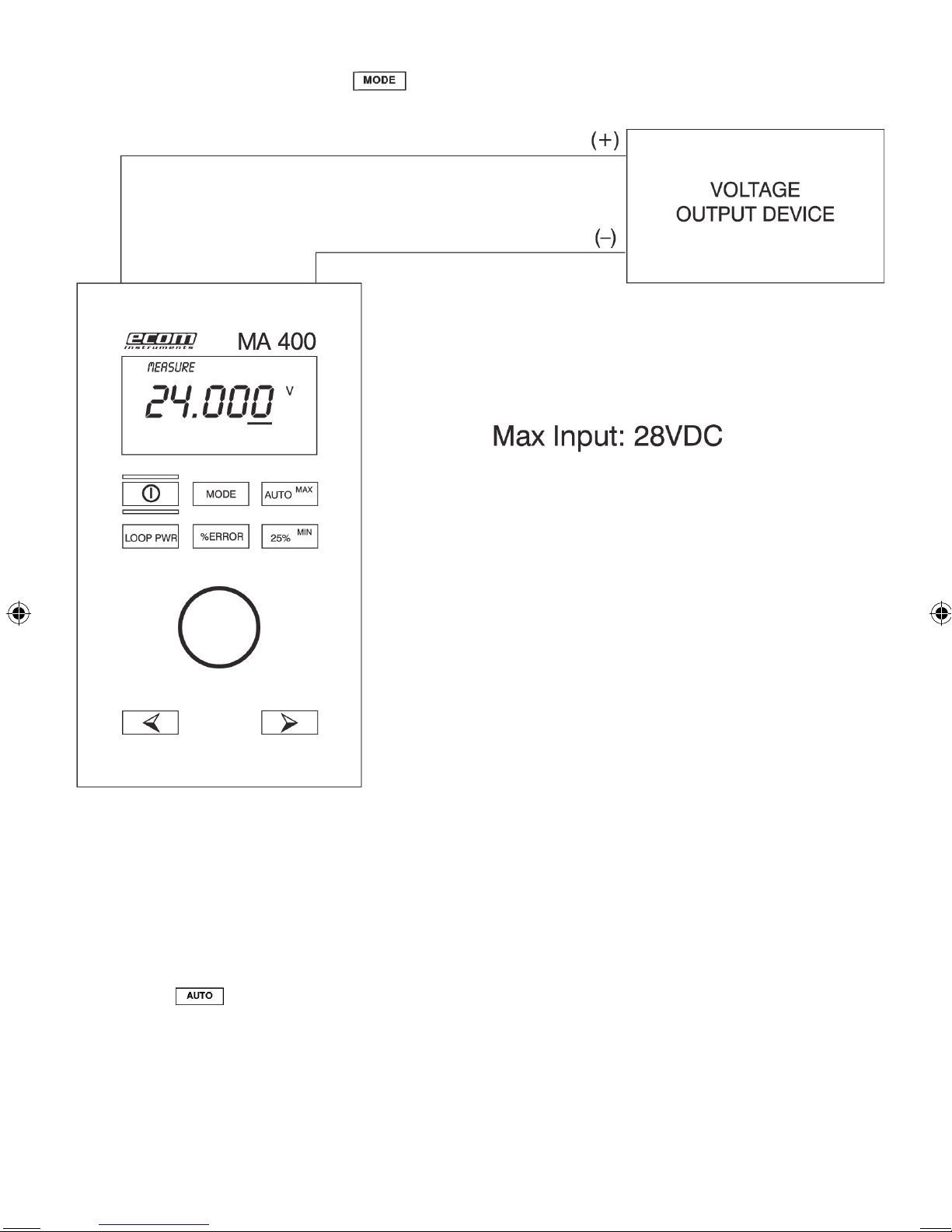
4.5 Voltage Measure
Figure 6 shows how to connect the MA 400 to measure DC voltage up to 28 volts. To activate the volts
measure function simply press the key to toggle through the functions until the volts measure
mode is reached. The input impedance of the MA 400 ≥1 meg ohm while in this mode.
Figure 6 - Measuring 0 to 28 VDC
5. Advanced Operating Modes
5.1 Auto Step/Ramp Mode
The MA 400 has the ability to step the mA output in 25% steps automatically in 5 second intervals.
It can also ramp the mA output from 4 mA to 20 mA then back to 4 mA in a linear fashion automatically.
To activate the Auto-Step/Ramp mode use the following procedure:
1) The Auto Step/Ramp function can be used in either the source mA or simulate mA mode.
Place the MA 400 in one or the other mode.
2) Connect the MA 400 to the device under test.
3) Press the key once for the step mode, twice for the slow ramp mode and three times for
the fast ramp mode. With each press a small annunciator will appear on the lower left side of the
LCD indicating which one of the step/ramp modes has been selected.
4) Once enabled the step/ramp mode will run continuously until another key is pressed.
BAL MA 400.indd 24 28.11.2005 10:18:02 Uhr

25
5.2 Percent Error Mode
This unique feature will calculate error as a percentage of span (4 mA to 20 mA yields a 16 mA
span). The percent error feature allows the user to “Zero Out” the %mA display so that the
deviation from the ideal value can be displayed on the % error display. The procedure is as follows:
1) Connect the MA 400 to the unit under test.
2) Place the MA 400 in one of the mA output modes (source or simulate).
3) Adjust the MA 400 to the desired output.
4) If the unit under test does not read exactly as it should, hold down the key and adjust the
knob unit until the unit under test reads correctly. Continue to hold down the key.
5) The reading in the % display area will be the error or deviation calculated as a percentage of span.
6) When the key is released the % display will return to normal operation.
5.3 Min/Max Datalogging
When the MA 400 is in any of the measure modes (mA, mA w/loop power or voltage) it will
continuously monitor and store the minimum and maximum values for that particular input
mode. To operate the datalogging feature use the following procedure:
1) Place the MA 400 in one of the measure modes.
2) Connect the MA 400 to the unit under test.
3) Clear the min/max memory by pressing both keys (min and max) simultaneously.
The LCD will display “CLR” when the memory is cleared.
4) Allow the unit to log min. and max. for as long as required.
Note: You may want to disable the Battery Save feature before using the Dataloggiong
Mode to prevent the MA 400 from turning off prematurely.
5) At any time press the min. or max. to display the value stored.
6) Turning off the MA 400 or changing modes will clear the memory. Be sure to record
your data before turning off the unit.
6. Maintenance
6.1 Battery Selection
The MA 400 operates on a standard 9V alkaline battery or an optional rechargeable 9V Ni-Cd
battery. For most applications the 9V alkaline battery will suffice; however, in heavy use applications
the 9V Ni-Cd may be a better choice.
The 9V Ni-Cd battery supplied by Martel will offer approximately 3 hours of continuous use
at 12 mA output on a full charge (the alkaline battery will yield about 12 hours). The charger
supplied by Martel will provide an overnight charge rate (10-12 hours) and will also power
the MA 400 for bench use while maintaining a loat charge on the Ni-Cd battery.
mCaution: Never connect the AC adapter/charger with the 9V alkaline battery installed.
6.2 Input Protection
The MA 400 incorporates a fuseless input protection and will tolerate most misconnections up to
250 VAC or 250 VDC for up to 30 seconds duration. Because of this protection no maintenance
is required.
6.3 Calibration
The MA 400 is designed to hold its rated accuracy for a minimum of one (1) year. It is therefore
recommend that an annual re-calibration be done to ensure operation within specification.
BAL MA 400.indd 25 28.11.2005 10:18:02 Uhr
26
7. Specifications
Input Range mA: 0.000 to 24.000 mA
–25.00% to 125.00%
Output Range mA
Source/Simulate:
0.000 to 24.000 mA
–25.00% to 125.00%
Read VDC: 0 to 30 VDC
Accuracy: ±0.015% of reading ±2 counts
Resolution: 0.001 mA; 0.001 volts
Loop Supply Voltage: 24 VDC
Typical Drive Capability: 1200 Ω w/o HART™
950 Ω with HART™
Auto % Error Function: Yes
Selectable Decade Adjustment: Yes
Auto Step/Ramp: Yes
Preset Outputs: 5
Loop Power Measure Capability: Yes
Operating Temperature: –10°C to 55°C
Power Supply: 9V Battery
Rechargeable Battery Option: Yes, optional available
AC Adapter: Yes, optional available
Size: 5.7 x 3.15 x 1.43 in (145 x 80 x 37 mm)
Weight: 12 oz. (340 g)
BAL MA 400.indd 26 28.11.2005 10:18:02 Uhr

27
8. Warranty and liability
Under the general terms and conditions of business, ecom instruments GmbH offers a 2-year warranty
for function and materials on this product under the specified operating and maintenance conditions.
Not covered are all wearing parts (e.g. batteries, sensors, displays, lamps, etc.) as well as calibrations.
This warranty does not extend to products that have been used improperly, altered, neglected, dama-
ged by accident or subjected to abnormal operating conditions or improper handling.
In the event of a warranty claim, the faulty device should be sent in. We reserve the right to readjust,
repair or replace the unit.
The above warranty terms represent the sole rights of the purchaser to compensation and apply exclu-
sively and in place of all other contractual or statutory warranty obligations. ecom instruments GmbH
does not accept liability for specific, direct, indirect, incidental or consequential damages or losses,
including the loss of data, regardless of whether they are caused by breach of warranty, lawful or
unlawful actions, actions in good faith or other actions.
If in certain countries the restriction of statutory warranty and the exclusion or restriction of incidental
or consequential damages is unlawful, then it may be possible that the above restrictions and exclusi-
ons do not apply for all purchasers. If any clause in these warranty terms should be found to be invalid
or unenforceable by a competent court, then such a judgement shall not affect the validity or enforcea-
bility of any other clause contained in these warranty terms.
BAL MA 400.indd 27 28.11.2005 10:18:02 Uhr

ecom instruments GmbH
Industriestraße 2
97959 Assamstadt / Germany
Tel.: +49 (0) 62 94 / 42 24 0
Fax: +49 (0) 62 94 / 42 24 90
E-Mail: [email protected]
Internet: www.ecom-ex.com
5080AL01A00 11/05 Änderungen vorbehalten · Subject to change without notice!
BAL MA 400.indd 41 28.11.2005 10:18:10 Uhr
Table of contents
Other Ecom Test Equipment manuals


