Mityvac MV5545 User manual

USER’S MANUAL
FST PRO FUEL SYSTEM TESTER
MODEL MV5545

Cont nts
Introdu tion...............................................3
SafetyPre autions .........................................3
Spe ifi ations .............................................3
Components, Servi e Parts, and A essories . . . . . . . . . . . . . . . . . . . 3
StandardKitComponents................................3,4
Servi eParts.............................................5
FuelSystemTestAdapters................................6-7
Assembly................................................8
BypassHose ..........................................8
FlowmeterFa eplates...................................8
Conne tions .............................................8
Adapters..............................................8
BanjoConne tions......................................9
FlexHoseConne tions.................................10
Proper Use, Care, and Servi ing . . . . . . . . . . . . . . . . . . . . . . . . . . . . 10
Prin ipleofOperation......................................11
Fuel Delivery Basi s . . . . . . . . . . . . . . . . . . . . . . . . . . . . . . . . . . . . . . 11
Appli ationoftheFST ....................................11
Diagnosing Fuel Delivery Systems . . . . . . . . . . . . . . . . . . . . . . . . . . 11
SimulatingEngineDemand..............................12
Pinpointing Fuel System Malfun tions . . . . . . . . . . . . . . . . . . . . . 13
TypesofFuelDeliverySystems..............................14
Return Fuel Systems . . . . . . . . . . . . . . . . . . . . . . . . . . . . . . . . . . . . . 14
ReturnlessFuelSystems..................................14
Me hani allyRegulated.................................15
In-tank Filtering/In-tank Return . . . . . . . . . . . . . . . . . . . . . . . . . 15
External Filtering/In-tank Return . . . . . . . . . . . . . . . . . . . . . . . . 15
External Filtering/External Return . . . . . . . . . . . . . . . . . . . . . . . 15
Ele troni allyRegulated.................................16
Identifying Fuel Delivery Systems . . . . . . . . . . . . . . . . . . . . . . . . . . . 16
FuelSystemComponents..................................17
FuelTank...............................................17
Fuel Pump. . . . . . . . . . . . . . . . . . . . . . . . . . . . . . . . . . . . . . . . . . . . . . 17
Fuel Inlet Strainer/So k . . . . . . . . . . . . . . . . . . . . . . . . . . . . . . . . . . . 17
Fuel Filter. . . . . . . . . . . . . . . . . . . . . . . . . . . . . . . . . . . . . . . . . . . . . . . 18
PressureRegulator.......................................18
Fuel Lines . . . . . . . . . . . . . . . . . . . . . . . . . . . . . . . . . . . . . . . . . . . . . . 18
SetupandInstallation......................................19
Determining Where to Install the FST . . . . . . . . . . . . . . . . . . . . . . . . 19
InlineConne tion......................................19
Alternative Conne tion Lo ations . . . . . . . . . . . . . . . . . . . . . . . . . 19
Sele ting and Installing Adapters . . . . . . . . . . . . . . . . . . . . . . . . . . . 19
SettinguptheFSTPro....................................20
InstallingtheFSTPro.....................................20
TestingandDiagnosti s....................................22
ReturnFuelSystems .....................................22
Returnless Fuel Systems (Me hani al) . . . . . . . . . . . . . . . . . . . . . . . 26
Returnless Fuel Systems (Ele troni ) . . . . . . . . . . . . . . . . . . . . . . . . 28
Fuelvisualization.........................................31
PressureLeakdownTest ..................................31
Dis onne tingtheFST.....................................32
AppendixA..............................................34
AppendixB..............................................36
AppendixC..............................................38
AppendixD..............................................40
Page Numbe - 2

Introduction
The Mityva FST Pro Fuel System Tester is an advan ed
diagnosti tool designed for troubleshooting and pinpointing
ommon automotive fuel delivery system malfun tions,
in luding:
• Failing fuel pump
• Faulty pressure regulator
• Blo ked inline filter
• Blo ked inlet strainer/so k
• Pin hed or rushed fuel line
• Fuel ontamination
• Fuel tank vortex
• Fuel system leaks
This manual fo uses on the appli ation of the FST to modern
ele troni fuel inje tion (EFI) systems. However, it is equally
apable of diagnosing earlier fuel inje tion systems su h as
throttle body inje tion (TBI), ontinuous inje tion (CIS) and even
pre-fuel inje tion arbureted systems. A separate low pressure
gauge is available from Mityva for systems that operate below
15 PSI (100 kPa).
Saf ty Pr cautions
The use of this servi e tool requires the exposure of highly
flammable gasoline. To prevent fires, explosions and/or severe
injury, always apply extra pre autions when diagnosing or
working on fuel systems.
The FST Pro is designed for servi ing a variety of vehi les in a
safe, onvenient manner. However, fuel delivery systems vary
widely between makes and models of vehi les, potentially
requiring additional steps or equipment to perform a proper
servi e job. The pro edures outlined in this manual are to serve
as guidelines for the use of this equipment. In addition to these
guidelines, always follow the manufa turer’s re ommended
pro edures when servi ing ea h unique vehi le. Use ommon
sense in the appli ation of this tester; and do not attempt to
for e a test on a fuel system for whi h this equipment is not
designed to perform.
This tester is designed for use on gasoline/petrol engines only.
It is safe for use with gasoline and most gasoline additives, but
is not ompatible with diesel fuel or alternative/flex fuels that
ontain ethanol.
• Always read arefully and understand instru tions prior to
using this equipment
• Wear safety glasses at all times
• Operate the vehi le only in a well ventilated area, and away
from potential sour es of flame or ignition.
• Prior to starting an engine, make sure all omponents of the
tester, body parts, and personal lothing are lear of rotating
engine omponents
• Avoid burns by remaining autious of engine parts that may
be ome hot when the engine is running
• Never leave a vehi le unattended while testing
• Che k and se ure all fuel system onne tions before
starting the vehi le or a tivating the fuel pump
• Wear gloves and prote tive lothing to avoid the onta t of
gasoline on skin. If onta t o urs, immediately wash the
area and perform ne essary first aid
• Always keep a fire extinguisher on hand when performing
fuel related diagnosti s. Make sure the extinguisher is rated
for fuel, ele tri al and hemi al fires
• Avoid spilling fuel on hot engine parts. Clean-up any fuel
spills immediately after they o ur.
Spec f cat ons
Maximum Flow Capa ity: 1.0 gallon/minute (3.8 liters/minute)
Maximum Rated Pressure: 200 PSI (1340 kPa) (13.8 bar)
Compon nts, S rvic Parts
and Acc ssori s
The Mityva FST Pro ombines the highest quality materials
and workmanship to reate a durable, finely tuned diagnosti
tool, whi h with proper are will provide years of valuable
servi e. All omponents are designed and quality ontrolled
in the U.S.
Following is a list of standard omponents, servi e parts and
a essories relating to model MV5545. Components and
a essories are available from your lo al Mityva distributor.
Servi e parts, warranty information and te hni al servi e
information are available at the onta t information shown on
the front of this user manual.
Standard K t Components
Model MV5545 in ludes the following high quality omponents:
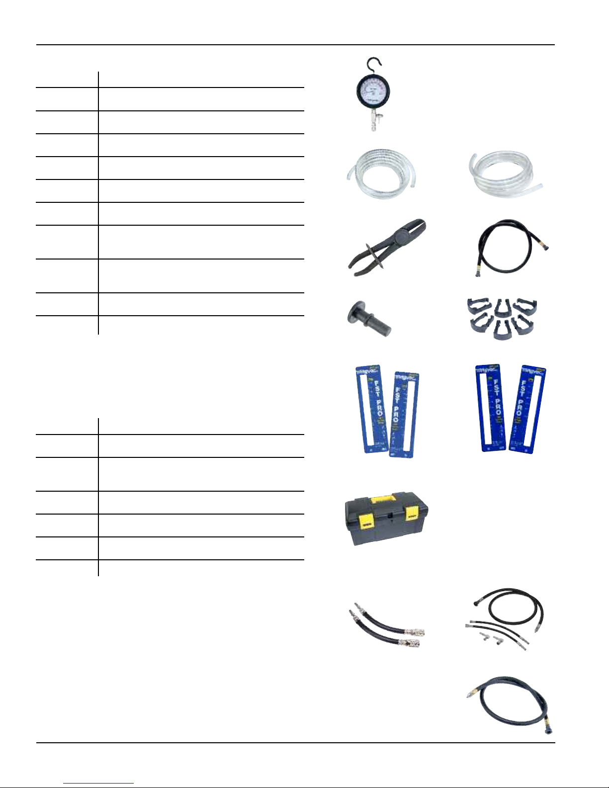
• 3.5" (90 mm) diameter diaphragm style Pressure Gauge
- 0 to 120 PSI (0 to 8 bar) (0 to 800 kPa) s ale of measure
- Push-button pressure relief valve
- 360° swivel hook
- Prote tive rubber boot
• Flowmeter Assembly
- Borosili ate glass variable area flowtube with prote tive
shield and pre ision aluminum float
- 3-way Flow Control Valve
- Fuel bypass port
- Male push-to- onne t, qui k- hange oupler
w/ S hrader valve
- (2x) Male SAE J2044 qui k- onne ts
- Repla eable fa eplates with 0 to 1.0 gallon/minute
s ale of measurement
- Prote tive rubber boot
• (2x) Repla eable flowmeter fa eplates with 0 to 4 liters/
minute s ale of measurement
• 1/8" (3 mm) ID x 6' (1.8 m) long Pressure Relief Hose
• 1/4" (6.5 mm) ID x 6' (1.8 m) long Bypass Hose
• (2x) Flowmeter Conne tion Hose
• (2x) S issor Hose Clamp
• (2x) Hose Plug
• (6x) Qui k- onne t Repla ement Clip
• Custom Storage Case
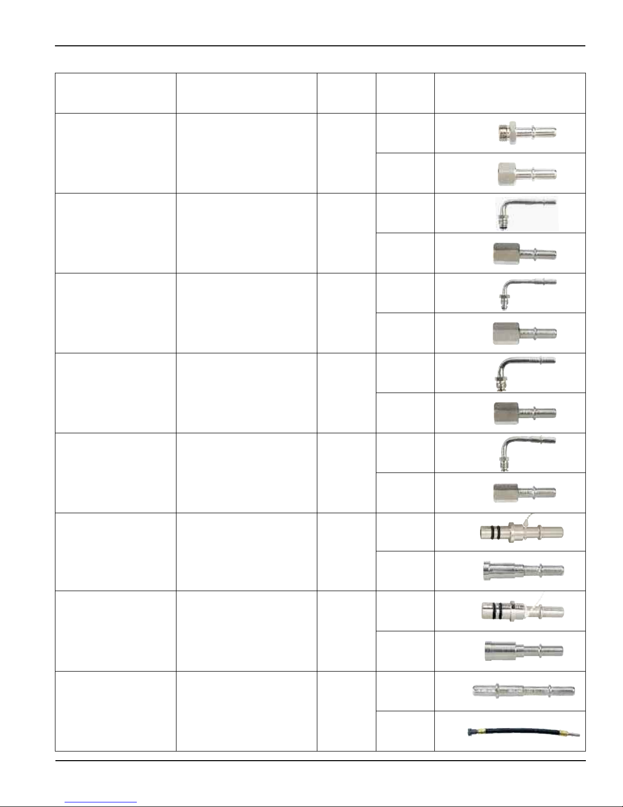
• Automotive Fuel System Test Adapters
(see Fuel System Test Adapters on page 6)
Page Numbe - 3

MVA5552
MVA5549
MVA509
Standard Kit Compon nts
Part Numb r D scription
824141 High Pressure Gauge
824149 Pressure Relief Hose (1/8"/3mm ID x 6'/1.8 m long)
824148 Bypass Hose (1/4"/6.5 mm ID x 6'/1.8 m long)
824144 S issor Hose Clamps (Qty 2)
824147 Flowmeter Hose (3/8"/9.5 mm ID x 4'/1.2 m long)
824173 Hose Plug (Qty 2)
824143 Flowmeter Fa eplates (Liters/Minute)
in ludes front and ba k plate
824142 Flowmeter Fa eplates (Gallons/Minute)
in ludes front and ba k plate
824172 Qui k- onne t Repla ement Clips (Qty 6)
824179 Storage Case
824141
824149 824148
824147824144
824143
824173 824172
824142
824179
Page Numbe - 4
Acc ssori s
Part Numb r D scription
MVA500 Low Pressure Gauge
MVA501 Flowmeter Fa eplate (0 to 60 Gallons/Hour)
in ludes front and ba k plate
MVA5549 MotorVa Adapter Set
MVA5552 Pressure Test A essory Kit
MVA506 Inline Pressure Test Assembly
MVA509 Extended Pressure Test Hose

Page Numbe - 5
S rvic Parts
Part Numb r D scription
1 824182 Flow Tube Shield
2 824177 Male Qui k-Conne t Fitting
3 824176 Bypass Port
4 824175 Flow Control Valve Knob
5 824174 Flowmeter Inlet/Outlet Conne tor (Qty 2)
6 824146 Flow Control Valve
7 824145 Flowmeter Seal Kit
824183 Wing-Style Hose Clamp (Qty 4)
824181 Flowmeter Boot
824180 Adapter O-Ring Kit
824178 Ford Springlok Tether with Clip
824181
824182
824178
824180
824174
824175
824145
824146
824176824177
824183
2
3
7
1
7
7
10
7
6
4
5

D scription Applications Ord r No. R f r nc
No.
GM/Chrysler Right Angle
Test Port Adapter
GM & some Chrysler
vehi les with 7⁄16" x 20
thread test port on fuel rail
MVA507** 20
Ford/Chrysler Right Angle
Test Port Adapter
Ford & some Chrysler
vehi les with .308 x 32
thread test port on fuel rail
MVA508** 21
GM/Chrysler
Test Port Adapter
GM & some Chrysler
vehi les with 7⁄16" x 20
thread test port on fuel rail
MVA510** 18
Ford/Chrysler
Test Port Adapter
Ford & some Chrysler
vehi les with .308 x 32
thread test port on fuel rail
MVA511** 19
3⁄8" Qui k- hange Adapter GM, Chrysler, Jeep/Eagle MVA512 1
1⁄4" - 3⁄8" Barbed
Flex Hose Adapter
Vehi les with 1⁄4", 5⁄16"
or 3⁄8" rubber to steel
hose onne tion
MVA505*
16
1⁄4" Flex Hose Adapter Vehi les with 1⁄4" rubber
to steel hose onne tion 16A
5⁄16" Flex Hose Adapter Vehi les with 5⁄16" rubber
to steel hose onne tion 16B
3⁄8" Flex Hose Adapter Vehi les with 3⁄8" rubber
to steel hose onne tion 16C
M8 x 1.0
Banjo Adapter Toyota MVA513
13B
13A
M10 x 1.0
Banjo Adapter Toyota MVA514
14B
14A
M12 x 1.25
Banjo Adapter
Toyota, Lexus, Geo, Honda, A ura,
Hyundai, Mazda, Daihatsu, Chrysler
imports
MVA515
15B
15A
M12 x 1.5
Banjo Adapter Audi, Volkswagen MVA516
9B
9A
M12 x 1.5
Ball Nose Adapter
European vehi les
with CIS fuel system MVA517
12A
12B
M14 x 1.5
Ball Nose Adapter
European vehi les
with CIS fuel system MVA518
10A
10B
Fu l Syst m T st Adapt rs
Page Numbe - 6 ** Not in luded in MV5545. Available individually or in MVA5552 Pressure Test A essory Kit

D scription Applications Ord r No. R f r nc
No.
M16 x 1.5
Ball Nose Adapter
European vehi les
with CIS fuel system MVA519
11A
11B
M16 x 1.5 Adapter GM Vorte MVA520
3A
3B
M14 x 1.25 Adapter GM Vorte MVA521
4A
4B
3⁄8" Flare Nut Adapter Carbureted & early
fuel inje ted systems MVA522
6A
6B
5⁄16" Flare Nut Adapter Carbureted & early
fuel inje ted systems MVA523
5A
5B
3⁄8" Spring Lo k Adapter Ford fuel inje tion systems MVA524
7A
7B
1⁄2" Spring Lo k Adapter Ford fuel inje tion systems MVA525
8A
8B
5⁄16" Qui k-Change Adapter GM, Chrysler, Jeep/Eagle MVA526
2B
2A
Fu l Syst m T st Adapt rs
Page Numbe - 7

Assembly
For flexibility and ease of storage, the FST Pro features a modular
design that is qui k to assemble and breakdown. Proper assembly
for testing is overed in the Setup and Installation instru tions
Bypass Hos
Prior to the first use of the FST, the 1/4" (6.5 mm) ID lear bypass
hose should be assembled to the bypass port extending from the
side of the flowmeter, above the flow ontrol valve. To onne t the
fuel bypass hose:
1. Uns rew the ompression nut from the fuel bypass port extending
from the side of the flowmeter just above the flow ontrol valve
(Fig. 1).
2. Slip the ompression nut over one end of the lear bypass hose,
1/4" (6.5 mm) ID x 6’ (1.8 m) long (Fig. 2).
3. Push the end of the bypass hose over the barb extending from
the bypass port (Fig. 3).
4. Slide the ompression nut up over the end of the tube and
thread it ba k onto the bypass port. Tighten the nut using a
7/16" open-end wren h (Fig. 4).
Flowm t r Fac plat s
The flowmeter is shipped with fa eplates installed on the front and
ba k. The flow s ale unit of measure printed on both plates is
gallons per minute (GPM). In luded with the kit are fa eplates with a
liters/minute (LPM) flow s ale. Fa eplates printed with a gallons per
hour (GPH) flow rate s ale an be pur hased separately.
The fa eplates are held se urely by the lip of the rubber boot that
surrounds the flowmeter. For a ura y, they pilot on the aps that
seal the top and bottom of the flowtube.
To remove the fa eplates, simply peel ba k the edges of the rubber
boot. To install new fa eplates, mat h the repla ement fa eplate to
the orre t side of the flowmeter, position the utout over the flow-
tube, and then arefully work the lip of the rubber boot ba k over
the edge.
Connect ons
The hoses that route fuel from the vehi le’s fuel delivery system
into and out of the FST Pro, utilize a spe ial female qui k- onne t
fitting (Fig. 5). This fitting was sele ted for several important reasons:
1. It onforms to the SAE J2044 spe ifi ation for fuel fittings
2. It is a ommon fuel delivery system onne tion on whi h many
manufa turers are standardizing
3. It does not restri t fuel flow, whi h ould ause a
false diagnosis
4. The onne tion releases with a simple push-button a tion. No
spe ial tools are required to dis onne t the fittings.
The flowmeter inlet and outlet ports, as well as the adapters and
fittings that onne t the FST into the fuel delivery system, have the
omplimenting male SAE J2044 endform (Fig. 6).
To se ure the male to female onne tion, simply push the male
endform into the female qui k- onne t until it snaps se urely into
pla e (Fig. 7). Always test the onne tion by trying to pull
it apart without pressing the release button.
Fig. 3
Fig. 1
Fig. 6
Fig. 5
Fig. 4
Fig. 2
Page Numbe - 8
Fig. 7

Fig. 9
Fig. 11
Fig. 10
Fu l Rail
Banjo
Fitting Banjo Bolt
Banjo Adapt r
Fu l Filt r
Page Numbe - 9
To release the onne tion, press and hold the release button on
the side of the female qui k- onne t, while pulling the onne tion
apart (Fig. 8). Do not attempt to release the qui k- onne t onne tion
using a dis onne t tool, as this may damage the fitting. Repla ement
lips are in luded if needed
Adapt rs
The FST Pro in ludes a sele tion of adapters for onne ting inline with
the fuel delivery systems of a wide range of automotive makes and
models. The hart on pages 6 and 7 outlines the adapters available,
and their appli ations. Ea h adapter is et hed with an identifi ation
number for easy referen e. Adapters an be pur hased separately in
sets a ording to the order number indi ated in the hart.
In most ases, sele ting and installing adapters into the fuel delivery
system and onne ting the FST for testing, is straightforward and
logi al. Simply mat h the fuel system onne tion to the equivalent
male and female adapter set, and install them as outlined in the
Setup and Installation instru tions later in this manual.
Banjo Conn ctions
Banjo style onne tions are ommonly used by many Asian and
European manufa turers to onne t a hose or fuel line to the filter
and/or the fuel rail. Often, this will be the best pla e to onne t the
FST inline with the fuel system. This type of onne tion may be a
little onfusing the first time it is en ountered.
A banjo onne tion onsists of a round, hollowed-out “banjo”
onne tor with two flat sides. A hollow bolt with a ross-hole
passes through the banjo onne tor and threads into the onne ting
omponent (i.e. filter, fuel rail). When the bolt is tightened, it reates
a se ure fa e-to-fa e seal through whi h the fuel flows. See Fig. 9 for
an illustration of this onne tion.
Two (2) threaded adapters and a losed end nut are required to
properly install the FST into a banjo style onne tion. Refer to the
adapter hart for a list of the banjo adapters in luded with the FST.
To install the banjo adapters:
1. Follow the proper pro edure under the Setup and Installation
instru tions to relieve the fuel pressure and prepare for
dis onne ting.
2. Loosen and remove the bolt from the banjo onne tion at the
fuel filter or fuel rail.
3. Pass the hollow adapter with the ross-hole through the banjo
fitting. Be sure to in lude a washer on both sides of the banjo
fitting (Fig. 10).
4. Thread the losed-end nut onto the end of the bolt and tighten
se urely with a wren h, trapping the banjo fitting.
5. Thread the hollow bolt adapter without the ross-hole into the
filter or fuel rail, in pla e of the original bolt, and tighten se urely
with a wren h. Be sure to in lude a washer between the fa e of
the filter or fuel rail, and the opposing fa e of the adapter bolt
(Fig. 11).
6. Follow normal testing pro edures.
NOTE: Always throw away the original used washers, and repla e
them with new when re onne ting the banjo fitting ba k to the
vehi le’s original spe ifi ation.
Fig. 8
Clos d
End Nut
Banjo Fitting
Banjo Bolt
Adapt r

Fl x Hos Conn ctions
In many ases it is onvenient to onne t the FST Pro into the fuel
delivery system at a lo ation where a flexible rubber hose is se ured
to a steel fuel line using a s rew lamp. A spe ial adapter set is
in luded with the FST Pro for installing it into this type of onne tion.
It in ludes a universal barb adapter, three flexible hose adapters
(1/4", 5/16", 3/8"), and four wing s rew lamps.
To install the flex hose adapters:
1. Follow the proper pro edure under the Setup and Installation
instru tions to relieve the fuel pressure and prepare for
dis onne ting.
2. Loosen the s rew lamp se uring the rubber hose to the steel fuel
line on the vehi le’s fuel delivery system, and arefully dis onne t
the rubber hose. (Fig. 12).
3. Insert the universal barb adapter (#16) into the rubber hose
(Fig. 13) and tighten the hose lamp (Fig. 14).
4. Sele t the appropriate size flex hose adapter (1/4", 5/16", or 3/8"),
and install it onto the steel fuel line (Fig. 15). Se ure it with one of
the wing s rew lamps provided (Fig. 16).
5. Follow normal testing pro edures.
Proper Use, Care and Serv c ng
With proper are and maintenan e, the FST Pro will provide years
of a urate, reliable servi e.
The FST is designed for use in testing modern fuel delivery systems
on vehi les equipped with gasoline powered ombustion engines.
• CAUTION: DO NOT USE THE FST PRO ON DIESEL SYSTEMS
• CAUTION: DO NOT USE THE FST PRO ON VEHICLES
OPERATING ON ALTERNATIVE FUELS SUCH AS E85
OR OTHER “FLEX” FUELS
• Always drain the fuel from the FST prior to storage.
• Always disassemble the FST and return it to the storage ase in
whi h it was originally pur hased.
• Inspe t omponents regularly for damage and repla e or repair as
ne essary:
- Che k hoses for ra ks and uts
- Che k adapters for damage and wear to threads and
sealing surfa es
- Che k female qui k- onne ts for wear and uts to o-rings
- Inspe t the male and female qui k- onne t omponents
where the pressure gauge onne ts to the flowmeter
• After installing the FST and pressurizing the fuel system, he k
the flowmeter for leaks. If any leaks are evident, immediately
relieve the pressure, dis onne t the FST, and send it to a servi e
enter for repair.
Fig. 16
Fig. 14
Fig. 12
Fig. 15
Fig. 13
Page Numbe - 10

Page Numbe - 11
Principl of Op ration
Fuel Del very Bas cs
Modern fuel inje ted engines rely on pre ision fuel delivery to
perform at peak output and effi ien y. It is the fun tion of the
fuel delivery system to ensure that proper fuel pressure and
volume are present in the fuel rail to meet the demands of the
engine under varying operating onditions. When a fuel delivery
system is designed to meet a parti ular vehi le’s requirements,
a fuel pump is sele ted that an deliver at least the maximum
fuel pressure and volume requirement of the engine. Other
omponents of the fuel delivery system a t upon the output of
the fuel pump to ensure the fuel pressure at the inje tors is
maintained at the predetermined spe ifi ation.
The maximum volume of fuel required by an engine varies
depending on its size. For example, an 8.0 liter engine running
at 3,000 rpm ould onsume as mu h as .34 gallons of fuel per
minute, while a 1.8 liter engine at the same speed would use
only .08 gallons per minute. When manufa turers design a fuel
delivery system for a spe ifi engine, they onsider the fuel
requirements based on the size, expe ted load and speed. This
data is used to program the vehi le’s Ele troni Control Module
(ECM), whi h in turn ontrols the opening and losing (duty
y le) of the fuel inje tors. With the ex eption of emerging
ele troni ally ontrolled fuel inje tion systems, the ECM
assumes that fuel pressure and volume to the engine are
maintained a ording to the designer’s spe ifi ations. If a
malfun tion in the fuel delivery system su h as a blo ked filter,
faulty pressure regulator, or bad fuel pump, auses pressure or
flow to vary at the fuel rail, the ECM annot dire tly sense this.
The only way the ECM an re ognize a fuel related problem
exists, is through the O2 sensor in the exhaust. The O2 sensor
alerts the ECM if the exhaust mixture is ri h or lean. The ECM
an only respond by opening the inje tors for longer or shorter
time periods to inje t more or less fuel. This may be enough to
mask small problems from the driver, but will result in poor fuel
effi ien y. If the vehi le owner does not noti e a de rease in
effi ien y, and have the vehi le servi ed, eventually the
malfun tion will lead to greater drivability problems.
To help ompensate for small fuel delivery problems su h as a
partially logged filter, manufa turers build a safety fa tor into the
fuel system so that it is apable of supplying somewhat greater
fuel pressure and volume than the engine will ever require.
Be ause of this, if a fuel delivery system is malfun tioning
enough to ause a noti eable drivability problem, with the
aid of the FST Pro, a te hni ian should be able to a urately
diagnose and pinpoint the ause of the problem.
Appl cat on of the FST
The fun tion of the FST Pro is to:
• Inform te hni ians that there is a malfun tion in the fuel
delivery system preventing the engine from re eiving the
optimal fuel pressure and flow it requires to perform at peak
effi ien y and performan e.
• Assist the te hni ian in a urately pinpointing fuel delivery
system malfun tions, so as to obsolete urrent onfusing,
time onsuming, and ostly troubleshooting pro edures.
The FST is able to perform these fun tions by providing
real-time values for fuel pressure and flow, and by allowing
the te hni ian to simulate varying load onditions on the engine
while the vehi le is idling in the shop. These fun tions are
performed by means of a pressure gauge, flow gauge
(flowmeter), and a patented flow ontrol valve.
The FST operates by measuring and a ting upon the flow of fuel
as it is pumped from the fuel tank to the engine by a vehi le’s
fuel delivery system. To a omplish this, the FST is designed to
be onne ted inline with the fuel system, su h that fuel flows
normally through the tester just prior to entering the fuel rail.
It is riti al that the FST be installed as lose as possible to,
and dire tly inline with the fuel rail so that the pressure and
flow measurements most a urately represent the onditions
experien ed by the engine. The further away from the fuel rail
that the tester is installed, the more likely the han e that an
external fa tor su h as a blo ked fuel line will affe t the
a ura y of the test results. Figure 17 illustrates a typi al instal-
lation of the FST on a return type fuel delivery system.
NOTE: When ondu ting an initial evaluation of the fuel system
using the FST, never install it with any omponent su h as a fuel
filter or pressure regulator lo ated between it and the fuel rail.
Doing so will likely ause the readings to deviate from the pres-
sure and flow that the engine is experien ing, thus redu ing the
a ura y and the reliability of the test results.
D agnos ng Fuel Del very Systems
Upon proper installation of the FST and vehi le startup (see
Setup and Installation), the value for fuel pressure at idle will be
indi ated on the pressure gauge, and the volume of fuel flowing
to the engine will be displayed by the flowmeter.
NOTE: While normal operating spe ifi ations for pressure and
flow will vary between vehi le makes, models, years and
engines, it is most likely that fuel pressure is the only one for
whi h a do umented spe ifi ation is available.
Regardless of the vehi le’s type of fuel delivery system
(see Modern Fuel Delivery Systems), the idle pressure an
immediately be noted and ompared to the manufa turer’s
spe ifi ation. However, the idle flow will vary signifi antly
depending on whether the fuel delivery system is return or
returnless. Assuming the fuel delivery system is operating
properly, the indi ated flow of a return system will represent the
total volume the pump is apable of produ ing at the spe ified
pressure. On the other hand, the indi ated flow of a returnless
system will represent only what the engine is using at idle.
Chan es are this volume is so low, that it will not even register
on the flowmeter.
Fig. 17

In regards to return fuel systems, knowing the pressure and flow at
idle is a very good indi ation as to whether the fuel system is
fun tioning properly. However, while pressure an be ompared to
a manufa turer’s spe , idle flow is not typi ally do umented. Most
return fuel systems will flow around .5 gallons (2 liters) per minute at
idle. However, the idle flow may range from .3 to .7 GPM (1.1 to 2.6
LPM) depending on the vehi le make, model, year and engine. Under
a heavy load, a 5.0 liter engine may require as mu h .5 GPM (2 LPM),
while a 2.0 liter engine may only require .2 GPM (.75 LPM). Any return
fuel system flowing less than .3 GPM at idle should be onsidered
suspe t for a malfun tion. Due to flow varian es, additional testing
des ribed below will provide a more a urate diagnosis of fuel
system performan e.
Using the FST to test a returnless system at idle will provide a
measurement for idle pressure. However flow at idle will provide no
additional insight as to its peak performan e apability. Using the
patented flow ontrol valve on the FST to exe ute simple pressure
and flow demand tests is required for an a urate diagnosis.
Simulating Engin D mand
At idle, an engine requires very little fuel, and pla es very little
demand on the fuel delivery system. A typi al fuel pump is apable of
providing up to 30X more fuel than an engine requires at idle. Testing
a fuel delivery system at idle may be a eptable if the driver has no
intention of a tually driving the ar, but what happens when a driver
needs to a elerate or ommit to a driving ondition that pla es a
load on the engine?
The key to determining if a fuel delivery system an meet maximum
engine requirements is to test it under the engine’s most demanding
onditions. Using patented te hnology, the FST Pro is the only tester
apable of simulating demand on a vehi le’s fuel delivery system to
determine if it an meet the peak requirements of the engine.
The FST has a built-in flow ontrol valve that enables an operator to
manually vary the flow restri tion su h that it simulates a ar’s throttle
position from idle, all the way to wide-open. The flow ontrol valve is
lo ated on the side of the FST flowmeter assembly. Arrows on the
fa eplate and rubber boot illustrate the three positions of the valve
as OPEN, CLOSED, and BYPASS.
When the valve is in the OPEN position pointing down, fuel flows
normally through the tester without affe ting the normal operation of
the fuel delivery system (Fig. 18). On a return system,
.3 to .5 GPM of flow is typi al, while a returnless system will indi ated
little to no flow. Fuel pressure should read within the manufa ture’s
spe ifi ation regardless of the type of fuel system.
When the valve is rotated 90° to the CLOSED position, flow through
the FST is ompleted restri ted (Fig. 19). On a return system or ele -
troni ally regulated returnless system, this is referred to as “dead-
heading” the fuel pump. The flow will drop to zero, and the pressure
gauge will indi ate the peak pressure output of the pump. Peak pres-
sure will typi ally be 50% to 100% higher than the normal operating
spe ifi ation. This is termed the Peak Pressure Test, and
is effe tive only on return or ele troni ally regulated returnless fuel
systems. Closing the valve on a me hani ally regulated returnless
system will have no effe t on fuel pressure.
CAUTION: A pump should never be dead-headed for longer than a
brief instant. Doing so an ause serious damage to the fuel system
and/or pump.
Page Numbe - 12
Fig. 18
Fig. 19

Fig. 20
Page Numbe - 13
When the valve is rotated to the BYPASS position pointing up, fuel is
routed through the bypass port lo ated on the side of the flowmeter
just above the flow ontrol valve (Fig. 20). Bypassing eliminates all
restri tion to the flow, and the maximum volume output of the pump
is indi ated on the flowmeter. Fuel pressure will drop to zero. This is
termed the Peak Flow Test, and is appli able to return and returnless
systems.
If the flow ontrol valve in the CLOSED position is onsidered to
simulate a losed throttle, and the BYPASS position is onsidered
to simulate wide-open throttle (WOT), then any position in-between
would represent some unique throttle position between idle and WOT.
With this in mind, the operator an simulate any engine demand
s enario by simply rotating the valve between CLOSED and BYPASS.
By monitoring the orresponding pressure and flow on the FST, the
fuel delivery system’s ultimate apability to meet engine requirements
an be determined.
Although it may sound ompli ated, applying this prin iple is quite
simple. For example a 3.8L engine with a maximum speed of 6,000
rpm an require an estimated flow of up to .34 GPM (1.3 LPM) of fuel
(see Appendix A). Keeping an eye on the flowmeter, the valve should
be rotated from the OPEN position, past the CLOSED position until
the reading a ross the top of the float is .34 GPM. The orresponding
pressure value should be noted. On a return system or ele troni ally
regulated returnless system, the pressure value should be higher than
the manufa turer’s spe ifi ation. On a me hani ally regulated returnless
system, the pressure should be within the manufa turer’s spe ifi ation.
Pinpointing Fu l Syst m Malfunctions
To pinpoint the ause of a fuel system malfun tion, a simple
knowledge of fuel system omponents, and their affe t on system
performan e, is ombined with the results from the tests above to
determine the most likely point of failure. For example, initial FST
testing of a return fuel system would yield values for four riti al
performan e indi ators, Idle Pressure, Idle Flow, Peak Pressure, and
Peak Flow. A logged inline fuel filter would restri t fuel flow, ausing
low values for idle and peak flow, but idle and peak pressure would
remain within spe . An under-restri ting pressure regulator would
produ e a higher than normal idle flow and low idle pressure, but
normal values for peak flow and peak pressure. Noting the values
of these test indi ators, and omparing them to the vehi le’s
spe ifi ations, the te hni ian an in most ases a urately pinpoint
the ause of a malfun tion.
Testing a returnless system will generate performan e measurements
for Idle Pressure, Peak Flow, and Peak Demand Pressure. The values
for these indi ators are applied in the same way, to pinpoint the ause
of a fuel system malfun tion.
This logi an be applied to all omponents that an influen e fuel
delivery system performan e. The details of this method are
do umented in the Testing and Diagnosti se tion of this manual.

Fig. 21
Fig. 22
Page Numbe - 14
Typ s of Fu l D liv ry Syst ms
For the purpose of a urately applying and testing with the FST Pro,
today’s fuel delivery systems an be divided into three typi al
onfigurations:
• Return (Bypass) Fuel Systems
• Returnless Fuel Systems – Me hani ally Regulated
• Returnless Fuel Systems – Ele troni ally Regulated
The fundamental differen es between return and returnless fuel
systems affe t the values for pressure and flow displayed by the FST,
and influen e its diagnosti apabilities. Even the differen es between
me hani ally and ele troni ally regulated returnless systems produ e
substantially varying results. The key to a hieving the most a urate
fuel system diagnosis begins with a basi understanding of the differ-
en es between fuel systems, and how the FST responds to ea h.
Return Fuel Systems
In a return type of fuel system, a ontinuous volume of fuel is pumped
to the engine via the fuel supply line. The engine uses what it needs,
and the rest is returned ba k to the tank via the fuel return line
(Fig. 21). The fuel pump re eives power dire tly from the ele tri al
system. Pump speed is not ontrolled by any external sour e, so
when the system is fun tioning properly, it outputs a onstant flow.
Fuel pressure in a return system is reated by a pressure regulator
mounted at the exit point of the fuel rail or fuel return line. As the
unused fuel leaves the fuel rail, it passes through the regulator, whi h
restri ts the volume of the returning fuel (see Fuel System
Components/Pressure Regulator). This auses ba kpressure to build
up in the fuel rail and fuel supply line, all the way ba k to the fuel
pump. This “ba kpressure” is the pressure at whi h fuel is delivered
to the inje tors, and what is referred to by the vehi le manufa turer’s
spe ifi ation for proper fuel pressure.
An inline filter is installed in the fuel supply line between the fuel pump
and the fuel rail to filter out impurities before they rea h the inje tors.
It’s typi ally mounted under the frame or in the engine bay, making it
relatively easy to repla e.
A properly fun tioning return type system will always deliver a mu h
greater volume of fuel to the engine than what it will require, even
under a heavy load or a wide-open throttle (WOT) ondition. A
normally fun tioning return fuel system will ontinuously ir ulate
around .5 gallon (2 liters) of gas per minute at normal operating
pressure. Ultimately, the fuel system designer determines what the
flow will be based on the engine requirements, but it will typi ally
vary between the .3 and .7 GPM depending on engine size.
Due to its layout, and the lo ation of riti al omponents, return
systems are the most easily and a urately diagnosed by the FST.
When installed and operated as re ommended, the FST an measure
four (4) riti al values that ombine to pre isely diagnose the fuel
system and pinpoint any malfun tions.
Returnless Fuel Systems
The term “returnless” des ribes fuel delivery systems that do not
return unused fuel ba k to the tank on e it has entered the fuel rail.
The fuel rail be omes the end of the line, where fuel pumped from the
tank remains under pressure until it’s used by the engine (Fig. 22).
Pr ssur T st Port
Pr ssur T st Port
Pr ssur
R gulator
Fu l R turn
Lin
Fu l Rail
Fu l Filt r
Fu l
Tank
Fu l Supply Lin
Inl t Strain r
Pump Modul
Pump Modul
Pr ssur R gulator
Fu l Rail
Fu l Filt r
Fu l
Tank
Fu l Supply Lin
Inl t Strain r

Fig. 25
Fig. 24
Fig. 23
Page Numbe - 15
Returnless fuel systems (me hani ally regulated) were pioneered by
Chrysler in the mid-90s. Sin e that date, other ar manufa turers
have been implementing returnless systems onto their ars. Now
returnless systems are ommon on most all new ars and light tru ks.
M chanically R gulat d
In the ase of me hani ally regulated returnless systems, the term
“returnless” an be misleading. Like a return system, the fuel pump
operates ontinuously, produ ing an un ontrolled output. Sin e the
engine will only use a portion of the total pump output, the ex ess
fuel must still be returned. This is done either in the tank, or the fuel
is routed just outside the tank for filtering, and then returned.
Me hani ally regulated systems utilize a spring operated pressure
regulator mounted in the tank as part of the pump module. The regu-
lator is very similar to those used in return systems, ex ept it is not
va uum- or pressure-modulated. Fuel pressure in returnless systems
is typi ally higher than return systems to ompensate for the la k of
modulation, and to help prevent the fuel from boiling in the fuel rail.
Me hani ally regulated returnless fuel systems employ one of three
basi on epts to filter the fuel and a ommodate the ex ess output
of the pump. All three methods utilize a fuel pump module with
built-in pressure regulator. The FST is very apable of diagnosing
a malfun tion of any of the three variations. However the type of
return/filtration method employed has a signifi ant impa t on the
FST’s apability to pinpoint the malfun tion. Refer to the Testing and
Diagnosti s se tion later in this manual for the proper appli ation of
the FST in diagnosing ea h system. In some ases, pinpointing the
exa t ause of the malfun tion may be irrelevant be ause the pump,
filter, and pressure regulator are all part of a module assembly that
must be repla ed as a omplete unit.
In-tank F lter ng/In-tank Return
This method involves filtering and returning the ex ess fuel without it
leaving the tank (Fig. 23). Both pressure regulator and filter are part of
the fuel pump module. Filtering is a omplished in one of three ways:
• A pre-pump filter is used to filter the fuel before it enters the pump.
• The filter is lo ated after the pressure regulator, where it filters the
unused fuel before mixing it ba k into the fuel reserve.
• The filter is lo ated in the pump module, between the pump and
the regulator.
Some manufa turers have designed in-tank filter/regulator systems
that use some variation or ombination of these three on epts to
produ e what they onsider to be the most effe tive system. In ases
involving in-tank filtering and return, all of the ontrol omponents are
in luded as part of the pump module assembly, and are most likely
repla ed as a omplete unit.
External F lter ng/In-tank Return
This system of fuel filtration and return uses a pressure regulator on
the pump module to regulate fuel pressure and return unused fuel
before it leaves the tank. The main filtration is handled by an inline
filter mounted externally between the tank and the fuel rail (Fig. 24).
External F lter ng/External Return
In this type of filtering/return system, the fuel is pumped out of the
tank to an external filter mounted on or near the tank (Fig. 25). The fil-
ter serves as a sort of manifold, with a single fuel supply line running
into one end of the filter, and two fuel lines exiting the filter. One of the
exiting lines supplies fuel to the engine, while the other returns the
unused fuel to the regulator and the tank.
Fu l Filt r
Fu l Filt r
Pr ssur R gulator
Fu l Pump
Inl t Strain r/Sock
Fu l R turn
Fu l Rail
Fu l Supply Lin

Fig. 27
Fig. 26
Page Numbe - 16
El ctronically R gulat d
Ford began developing an ele troni ally regulated returnless fuel
delivery system in the late nineties, and began implementing it on
their ars in the early to mid-2000s. This system shares some of the
features and benefits of both return and returnless systems, but with
the addition of advan ed ontrol te hnology. The two main differ-
en es of an ele troni ally regulated fuel system are the repla ement
of the me hani al pressure regulator with an ele troni pressure
sensor, and the introdu tion of a variable speed fuel pump (Fig. 26).
The fuel pressure sensor is mounted dire tly onto the fuel rail, whi h
ensures the most a urate reading of the pressure at the inje tors.
The signal from the pressure sensor is fed to the ECM where it is
ombined with other inputs su h as from the O2 sensor. The ECM
pro esses the data and uses it to ontrol the duty y le of the
inje tors and the speed of the fuel pump. Fuel pressure and volume
are ontrolled by the ECM speeding up or slowing down the fuel
pump. This eliminates the need for a pressure regulator.
Although a whole new level of te hnology and ontrol has been
introdu ed with this system, the engine requirements are still the
same. The FST is just as effe tive at diagnosing an ele troni ally
regulated system as a me hani al, and the test pro edures are
just as straightforward.
Ident fy ng Fuel Del very Systems
Begin by opening the hood and lo ating the fuel rail. If the engine
has only one bank of ylinders, there will be only one fuel rail.
Engines with two ylinder banks will typi ally have two fuel rails,
ea h feeding the inje tors in one of the banks. There will be a
rossover between the rails to allow fuel to flow from one side to
the other. Fuel rails vary in appearan e from simple round tubes to
square or re tangular in shape.
Look for the fuel line(s). They typi ally ome up from under the ar at
the base of the firewall, run up the firewall, and then extend over to the
fuel rail(s). A return system will have two lines, one supplying fuel from
the tank, the se ond returning the unused fuel ba k to the tank. It is
easy to onfuse fuel lines with lines for the evaporative system, so
inspe t them losely. Fuel lines will be either steel or fuel rated rubber.
Return systems will have a pressure regulator typi ally mounted on
the end of the fuel rail, su h that unused fuel flows out of the fuel rail,
through the pressure regulator, and into the return line. The pressure
regulator will typi ally have a va uum line atta hed, whi h adjusts
fuel pressure regulation a ording to engine speed (Fig. 27). Some
ars will have a pulse dampener, whi h an be easily onfused with
the regulator. The pulse damper is typi ally found on returnless
systems. It does not have a va uum line atta hed to it, and is om-
monly mounted at the inlet, or extends from the side of the fuel rail.
Returnless fuel systems will have a single fuel line running to the fuel
rail. There will be no fuel pressure regulator lo ated at the fuel rail.
Ele troni ally ontrolled fuel systems will have a pressure transdu er
mounted on the fuel rail (see Fuel System Components). The
transdu er will have an obvious ele tri al onne tion with three
to five wires extending from it.
Pr ssur T st Port
Pr ssur
S nsor
Pump Modul
ECM/PCM
Fu l Rail
Fu l Filt r
Fu l
Tank
Fu l Supply Lin
Pr ssur R gulator
To Manifold
Vacuum or
Atmosph r Fu l R turn Lin
Fu l Supply Lin

Page Numbe - 17
Fu l Syst m Compon nts
The modern fuel delivery system is omprised of several riti al
omponents. A malfun tion of one or more of these an ause
the system to fail or under perform. The fun tion of the FST is
to diagnose when a fuel system failure has o urred, and to
pinpoint the omponent(s) whi h aused the failure. To rea h
an a urate diagnosis, a basi knowledge of the fuel system
omponents and their role in a hieving optimum engine
performan e is helpful. Following is a list of ommon ompo-
nents that ontribute to the fun tion of the fuel delivery system.
A failure of one or more of these omponents an typi ally be
diagnosed using the FST Pro:
• Fuel Tank
• Fuel Pump
• Fuel Pump Inlet Strainer/So k
• Inline Fuel Filter
• Pressure Regulator
• Fuel Lines
Fuel Tank
The fuel tank serves as a reservoir to store the fuel until it is
needed by the engine. Fuel tanks have been manufa tured from
a variety of metals and plasti s. The fuel pump hangs down into
the tank, drawing the fuel from very lose to the bottom. The
most likely influen es of the fuel tank towards a fuel system fail-
ure would be the result of rust or s ale produ ed by a metalli
tank, the olle tion of impurities introdu ed from the outside, or
a dented tank that interferes with the fun tion of the fuel pump.
It is riti al that the fuel tank be emptied, leaned, and inspe ted
any time a fuel pump is repla ed or impurities are suspe ted.
Fuel Pump
The fuel pump is the heart of the fuel delivery system. It pumps
fuel from a vehi le’s fuel tank to the engine, where it is mixed
with air and inje ted into the ylinders for burning. Fuel pumps
in most modern fuel delivery systems are lo ated inside the fuel
tank, and run on ele tri ity supplied by the vehi le’s ele tri al
system. They pump a ontinuous volume of fuel at a given
voltage, and are typi ally extremely reliable when operated
under the onditions for whi h they are designed. Despite their
reliability and the high ost and hazard of repla ement, fuel
pumps have a higher return rate than almost any other
automotive part. They are ommonly misdiagnosed and
needlessly repla ed, osting onsumers, repair shops and
manufa turers millions of dollars ea h year. It’s estimated that
80% or more of returned pumps are found to fun tion properly
when tested by the manufa turer.
Most me hani ally regulated fuel delivery systems operate the
fuel pump at one speed, based on a onstant voltage from the
ele tri al system. However some automotive manufa turers
have begun in orporating two or three speed pumps to improve
effi ien y and redu e emissions. Like ele troni ally regulated
returnless systems, the speed of the pump is ontrolled by the
ECM. However the ECM does not in rease pump speed based
on fuel pressure. In su h a ase, the fuel pump may not
in rease speed/output in rea tion to the simulated load method
used by the FST. Instead, a s anner or manufa turer’s software
is required to manually in rease the speed in order to test the
peak apability of the pump. The manufa turer’s servi e manual
should do ument this in their fuel system diagnosti pro edure.
Fuel pumps fail or fail to perform due to high mileage,
ontaminated fuel, or ele tri al problems. While there is no fix
for wear due to high mileage, fuel and ele tri al problems an
be identified, orre ted, and prevented. In the ase of fuel
ontamination, it is almost ertain the pump will have to be
repla ed due to irreversible damage. However, ele tri al issues
su h as a loose ground, bad onne tion, or low voltage, an
many times be orre ted before the pump experien es any
permanent damage.
Contaminated fuel is a major ause of fuel pump failures. Dirt,
debris and s ale an log the inlet strainer and fuel filter ausing
the pump to work harder and redu e its life. They also wreak
havo inside the pump by a ting like an abrasive to grind at
parts. Chemi al ontaminates an ause pre ision made
omponents to swell or gum-up, leading to under-performan e
or omplete failure. For all of these reasons, fuel tanks should
be ompletely drained and professionally leaned, or possibly
even repla ed, ea h time a fuel pump is repla ed or
ontamination is suspe ted.
Che k all ele tri al onne tions. When ele tri al onne tions fail,
voltage to the pump will be redu ed, ausing the pump to run
ineffi iently and ultimately redu ing its life. Che k the vehi le
harness plugs for soot or burned wires. Che k the pump
module/hanger plug for melted plasti or loose terminals on the
flange. Perform a voltage drop test a ross all ele tri al onne -
tors and all ele tri al omponents involved with the fuel pump.
Also he k the wires from the pump to the flange when repla ing
a pump-only appli ation. A damaged wiring harness, if not
repaired, may ause a premature failure to a repla ement pump.
Ea h omponent of the fuel delivery system has its own unique
affe t on pressure and flow when it malfun tions. When a fuel
pump is failing or under-performing, its total output de lines,
ausing both flow and pressure to drop. When testing a
vehi le’s fuel delivery system with the FST Pro, the affe ts of an
under-performing pump an be diagnosed by observing how
pressure and flow respond to simulated load onditions. Other
ommon test methods su h as testing amperage draw or
pressure alone an not reliably dete t a malfun tion, and/or
do not have the apability to simulate a load ondition. This,
ombined with a la k of fuel delivery system knowledge and
training, leads to the high rate of misdiagnosis.
Fuel Inlet Stra ner/Sock
Fuel flows from the tank through an inlet strainer/so k before
entering the fuel pump. It is designed to apture dirt and debris
that ould damage the pump. Be ause it is not easily a essi-
ble, it is large in size so that it should not have to be repla ed
ex ept when the pump is servi ed or repla ed.
If the inlet strainer be omes logged or plugged, it will limit the
amount of fuel flowing to the fuel system, to the point that it will
starve the engine of adequate pressure and volume. This an
reate drivability problems. In addition, a logged strainer makes
the fuel pump work harder to pull fuel through it, and an starve
the pump of fuel that it needs for lubri ation and ooling. All of
these fa tors an lead to premature pump failure.

Page Numbe - 18
A logged inlet strainer an starve the fuel pump of fuel, ausing
it to avitate. Cavitation will reate rapid hanges in fuel density,
ausing the float in the FST flowmeter to boun e up and down.
It an also ause the needle on the pressure gauge to boun e.
In addition, as the pump tries to pull gas through the logged
strainer, it reates a pressure drop that may ause air bubbles to
form and be ome visible.
Always inspe t the inlet strainer whenever a fuel pump is being
servi ed. If it is rusty, brown, or dark olored, proper a tion must
be taken to lean and servi e the tank. Never reuse old filters or
strainers, espe ially when installing a new fuel pump.
Fuel F lter
Fuel filters ensure that the fuel sent to the inje tors is lean.
They are installed in the fuel supply line, su h that fuel flows
from the tank, through the filter on its way to the fuel rail. Filters
are typi ally mounted under the ar along the frame, or in the
engine bay where they are relatively a essible for periodi
repla ement.
A lean filter should have little or no affe t on the pressure or
flow of fuel. A logged filter be omes a restri tion to flow. As
blo kage in the filter in reases, flow de reases. Depending on
the type of fuel delivery system and the level of restri tion, a
logged fuel filter will ause pressure to in rease between the
pump and the filter, and/or de rease between the filter and the
fuel rail. Be ause fuel systems are designed to deliver a greater
volume and pressure than the engine will require, small
blo kages may not be noti eable. However, as the restri tion
in reases, it will ause the engine to under-perform and/or stall
or hesitate under load. In addition, it auses the fuel pump to
work harder, whi h an lead to premature failure.
The FST Pro an a urately diagnose a logged fuel filter by
omparing flow and pressure levels at idle with those at
simulated load onditions.
Pressure Regulator
The pressure regulator is a omponent of me hani ally regulated
fuel delivery systems. It reates and maintains the pressure
required by the fuel inje tors to perform at their optimum
effi ien y. While it’s the fuel pump that reates the flow of fuel,
it’s the regulator that reates the pressure by restri ting the flow.
The pressure regulator uses a spring to ontrol the amount of
restri tion based on the pressure in the fuel system. When the
engine is off and there is no flow of fuel, the regulator spring
ompletely loses the restri tion, trapping pressure in the fuel
rail. When the engine is started, the restri tion auses the
pressure to in rease in front of the regulator. When fuel system
pressure builds to the optimum level, it over omes the for e of
the regulator spring, and the regulator opens to allow fuel to flow
through. As the fuel requirements of the engine differ from idle,
the regulator automati ally in reases or de reases the restri tion
to maintain the optimum pressure at the inje tors.
Pressure regulators used in return type fuel systems are
mounted on the fuel rail, and are either va uum or atmospheri
modulated. Va uum modulated pressure regulators use manifold
va uum to maintain a onstant pressure differential a ross the
fuel inje tors. This means that fuel rail pressure will vary
depending on manifold va uum. At idle, manifold va uum is
high. This auses the regulator to pass more fuel ba k to the
tank, lowering fuel pressure in the rail. When the throttle is
opened, manifold pressure drops. This auses the regulator
to lose, allowing less fuel flow ba k to the tank, so fuel rail
pressure in reases. Va uum modulation ensures the inje tors
are re eiving the proper fuel pressure for peak engine
performan e, depending on the engine’s requirements.
Atmospheri modulated pressure regulators modify fuel
pressure with hanges in atmospheri pressure. This allows
fuel systems to ompensate for hanges in altitude.
Atmospheri modulated fuel systems rely more on the ECM to
ontrol fuel inje tion performan e using other feedba ks su h
as the O2 sensor, and ontrolling fuel inje tor duty y le.
Me hani ally regulated returnless fuel delivery systems use a
onstant pressure regulator lo ated in the fuel tank, as part of
the fuel pump module. It maintains onstant pressure due to
a fixed spring rate. Fuel pressures in returnless systems are
typi ally higher than return systems, to ompensate for the la k
of modulation.
When diagnosing a potential pressure regulator failure, onsider
what happens in the fuel delivery system when the regulator fails
to maintain the proper fuel pressure. If the regulator sti ks in the
open position, su h that there is little or no restri tion to flow,
fuel will flow freely through the regulator and ba k to the fuel
tank. Fuel system pressure may drop drasti ally below what
is required by the inje tors. Depending on how the low the
pressure drops, the malfun tion may not be noti eable when
the ar is idling or running under a minimal load. But if a heavy
load ondition is introdu ed on the engine, su h as a hard
a eleration, the la k of pressure will ause the engine to
stumble and la k power.
If the sti king regulator was over-restri ting the flow of fuel ba k
to the tank, it would ause fuel system pressure to in rease
above normal. Be ause the fuel pump produ es mu h greater
flow than what the engine will typi ally require, this malfun tion
may not be evident at idle or at minimal load onditions.
However, fuel e onomy ould drop severely as the high
pressure auses too mu h fuel to be inje ted into the engine.
Fuel L nes
Fuel lines are manufa tured from steel, rubber or plasti . They
an affe t fuel delivery performan e if they be ome logged,
pin hed, kinked, dented or ruptured. Be ause fuel delivery
systems keep fuel under pressure, a ruptured fuel line will be
evident by leaking fuel. Likewise, most other restri tions an
identified with a simple visual inspe tion.
A restri ted fuel supply line due to damage or blo kage will have
the same affe t as a logged inline filter. If FST Pro test results
indi ate a restri tion to the supply of fuel, always make a visual
inspe tion of the lines before performing additional diagnosti s
or repla ing a suspe t omponent.
A restri ted fuel return line due to damage or blo kage will have
the same effe t as an over-restri ting pressure regulator. If FST
Pro test results indi ate a restri tion to the return of fuel, always
make a visual inspe tion of the lines before performing addition-
al diagnosti s or repla ing a suspe t omponent.

Fig. 28
Fig. 29
Fig. 30
Page Numbe - 19
S tup and Installation
Determ n ng Where to Install the FST
Inlin Conn ction
Regardless of the type of fuel delivery system, the FST Pro is most
effe tive at diagnosing malfun tions when onne ted inline with the
flow of fuel. The initial installation should be made at an a ess point
along the fuel supply line, as lose as possible to the fuel rail (Figs.
28, 29 and 30). At this lo ation, the fuel pressure and flow measured
by the tester will most a urately represent the onditions within the
fuel rail. Due to some engine ompartment layouts and onne tor
lo ations, it may be ne essary to onne t the tester dire tly after the
in-line fuel filter, whi h may be lo ated in the engine ompartment,
under the frame, or near the fuel tank. In this ase, be sure to arefully
inspe t the fuel supply line between the tester and fuel rail for any
irregularities su h as leaks, rimps, or kinks, as these may ause a
false diagnosis based on the tester readings.
Alt rnativ Conn ction Locations
Conne ting the FST inline as instru ted above for the initial test,
ensures the most a urate fuel system diagnosis. However, in some
instan es it may be benefi ial to onne t the tester at alternative
lo ations in order to more a urately pinpoint the exa t ause of a
malfun tion. Performing additional diagnosti s at different onne tion
lo ations is detailed in the Testing and Diagnosti s se tion of this
manual.
Select ng and Install ng Adapters
The FST Pro in ludes adapters for onne ting the tester inline with
the fuel delivery systems of a wide variety of US, European, and Asian
manufa tured ars and light tru ks. In most ases, making an inline
onne tion with the FST requires two adapters, one to onne t the
fuel line from the fuel tank to the FST inlet, and the se ond to onne t
the FST outlet to fuel line ontinuing on to the engine.
The FST utilizes female 3/8” SAE J2044 qui k- onne tors on the
ends of the inlet and outlet hoses that onne t into the fuel line. This
is the same onne tion that is used on many newer makes and mod-
els of ars. If the vehi le being tested uses this adapter style, only one
intermediate adapter will be required. This should be evident upon
inspe tion of the vehi le’s onne tion.
All of the adapters in luded with the FST have an identifi ation num-
ber stamped into them for easy identifi ation. To determine an
adapter’s size and appli ation(s), use its number to lo ate it in the
Adapter Appli ation Chart on page 6 and 7.
Most of the adapters and their onne tion methods are straight for-
ward. Simply mat h the FST test adapter to the type of fuel line on-
ne tion used on the vehi le. All adapters should thread or snap
together easily to form a leak-proof seal. Always err on the side of
aution. If the onne tion has to be for ed, or if there is looseness in
the onne tion, do not attempt to pressurize the system. Conta t the
Mityva te hni al servi e department at the number on the front of
this manual if there are any questions or on erns about the onne -
tion.
If you have a ess to the fuel system adapters manufa tured by
MotorVa for their CarbonClean® fuel system leaner, these may be
utilized with the FST Pro. Mityva model MVA5549 MotorVa Adapter
Kit is available to make this onversion.
NOTE: In many ases it may only be possible to identify the type of
onne tion after the fuel line has been dis onne ted. However, to

Fig. 35
redu e fuel spillage, whenever possible, try to sele t the required
adapters before dis onne ting the fuel line, and have them ready to
install.
Sett ng-up the FST Pro
On e the installation point has been determined, follow the instru -
tions below to setup the tester prior to dis onne ting the fuel line.
1. Pla e the vehi le transmission in park or neutral, apply the parking
brake, and turn the key off.
2. Hang the pressure gauge under the vehi le hood or other appro-
priate lo ation.
3. Conne t the flowmeter to the pressure gauge using the female
push-to- onne t oupler extending from the bottom of gauge,
and the male onne tor lo ated on top of the flowmeter. Make
sure the qui k- onne t sleeve snaps forward to lo k the onne -
tion.
NOTE: The flowmeter should hang verti ally for the most a urate
fuel flow measurement.
4. Conne t the 1/8" (3 mm) lear pressure relief hose to the barb
extending from the push-button pressure relief valve lo ated just
under the gauge (Fig. 31).
5. Pla e the free ends of the bypass hose and pressure relief hose
into an approved gasoline fuel ontainer. Se ure hoses in fuel
ontainer as ne essary to prevent spills.
6. Conne t one end of ea h 3/8" inlet and outlet onne tion hoses
to the bottom fittings on the FST flowmeter (Fig. 32).
Install ng the FST Pro
1. Be sure the vehi le transmission in park or neutral, the parking
brake is applied, and the engine is off.
2. Follow the vehi le manufa turer’s re ommended pro edure to
relieve the pressure from the vehi le fuel delivery system.
3. Lo ate the fuel supply line to the engine’s fuel rail, and sele t the
best lo ation to dis onne t the supply line and install the FST
(Fig. 33). If un ertain of the proper onne tion point, see the
previous se tion entitled Determining Where to Install the FST.
For additional assistan e, onsult the vehi le manufa turer’s
servi e information, or refer to the Types of Fuel Delivery Systems
se tion earlier in this manual.
If the engine has a over, it will most likely have to be removed to
gain appropriate a ess.
4. Remove or dis onne t any obsta les required to gain a ess to
the onne tion, and pla e shop towels under and around the
onne tion to absorb fuel from the dis onne ted line.
To minimize fuel spillage and redu e the amount of time the fuel
line is dis onne ted, try to identify the type of onne tion before
dis onne ting the fuel line, and have the required FST onne tion
adapter(s) readily available (see Sele ting and Installing Adapters
above). Also, identify the inlet and outlet hoses to the tester, and
keep them onvenient.
5. Follow the vehi le manufa turer’s servi e information for the prop-
er method to dis onne t the fuel line. Spe ial wren hes or dis-
onne t tools may be required (Fig. 34).
WARNING: Avoid spilling fuel on hot engine parts. Clean-up any
fuel spills immediately after they o ur.
6. Install the appropriate adapter into the fuel supply line extending
from the tank (Fig. 35).
Page Numbe - 20
Fig. 32Fig. 31
Fig. 33
Conn ction Location
Fu l Lin
Fig. 34
Table of contents
Other Mityvac Test Equipment manuals

Mityvac
Mityvac SILVERLINE ELITE MI8550 User manual

Mityvac
Mityvac MV5536 User manual

Mityvac
Mityvac MV4530 User manual

Mityvac
Mityvac SILVERLINE MV8500 User manual

Mityvac
Mityvac MV5545E User manual

Mityvac
Mityvac MV5520 User manual

Mityvac
Mityvac MV5546 User manual

Mityvac
Mityvac MV4560 User manual

Mityvac
Mityvac 04050 User manual

Mityvac
Mityvac MV5530 User manual