Arteche saTECH TSB-14 User manual

Test Block saTECH TSB-14
User Manual

The test block manual contains instructions for
installation, commissioning and operation.
However, the manual cannot cover all
conceivable circumstances or include detailed
information on all topics.
In case of questions or specific problems do
not take any action without proper
authorization.
Please contact the technical sales of Arteche
and request the necessary information.
All agreements and commitments, legal
relationships and obligations of Arteche Smart
Grid SL including settlements of warranties,
they result solely from the applicable purchase
contract, which is not affected by the contents
of the manual.
All trade names and registered trademarks
mentioned in this document or not, are the
property of their owners.
This manual is for informational purposes and
is subject to change without notice.
Rev.: 2.0
Int. Ref.: V05
Date: 13/09/2017
© Electrotécnica Arteche Smart Grid, S.L.
RESTRICTED USE DOCUMENT.
Total or partial reproduction of this information
without having to do the prior express written
permission is prohibited.
Document subject to change.

INDEX OF CONTENTS
Test Block saTECH TSB-14 | User Manual | Rev.: 2.0
3
Chapter 1. Supply features..........................................................................................4
Chapter 2. Main features..............................................................................................5
Chapter 3. Safety Basic Measures and Recommendations......................................7
Chapter 4. Principle of Operation ...............................................................................8
Chapter 5. Technical Data .........................................................................................15
Chapter 6. Model Selection .......................................................................................16
Chapter 7. Dimensions, installation and connections ............................................17
Chapter 8. Maintenance.............................................................................................22

SUPPLY FEATURES
Test Block saTECH TSB-14 | User Manual | Rev.: 2.0
4
Chapter 1. Supply features
saTECH TSB test blocks facilitate secondary testing load of any power system, allowing rapid
monitoring, insulation and testing of the field elements.
Today the Satech TSB range includes blocks of 14 test circuit: Satech TSB-14.
The Satech TSB-14 and TSB-14RC (Henceforth, TSB14 shall include both lines unless
otherwise specified).product line is formed by TSB-14 test blocks and associated TSB-14-P test
plug. They are supplied independently.
In the case of saTECH TSB-14 tests block, its corresponding package contains:
Kit of cabinet fixing screw
Kit of rear block connection screw.
Kit of earth connections screw.
Block tests saTECH TSB-14 of the requested model, with its corresponding front
cover
In the case of saTECH TSB-14-P tests block, its corresponding package contains:
saTECH TSB-14-P Test Plug
TSB-P Protector for transport
Instructions for Test Plug insertion and extraction
Kit (14 units) plug plastic covers that cover the full spectrum of contacts 1, 2, A
and B
The line of 14 circuits blocks and plugs in the range saTECH TSB, is available for installation in
horizontal and vertical positions respectively. The selection of each model is shown later in
other chapters of this manual.

MAIN FEATURES
Test Block saTECH TSB-14 | User Manual | Rev.: 2.0
5
TSB-14-P-V
saTECH TSB 14-H/V (TEST BLOCK)
saTECH TSB-14-P-H/V (TEST PLUG )
saTECH TSB-14RC-H (TEST BLOCK) saTECH TSB-14RC-P-H (TEST PLUG)
Chapter 2. Main features
The ARTECHE saTECH test block allows the isolation of circuits and corresponding IEDs in a
safe and easy way, separating fully the IEDs equipment and / or circuits of the system from the
field elements, thereby eliminating any risk to the user.
TSB-14-V
TSB-14-H
TSB-14-P-H

MAIN FEATURES
Test Block saTECH TSB-14 | User Manual | Rev.: 2.0
6
The main features of the line of blocks and plugs of 14 circuits in TSB SaTECH range are the
following:
14 circuits, versatile selection, with different configuration (trips, voltages and
currents, contact type 1, 2, A and B, with the alphabetical designating currents). This
configuration should be defined prior to the order, because afterwards this
configuration can’t be modified.
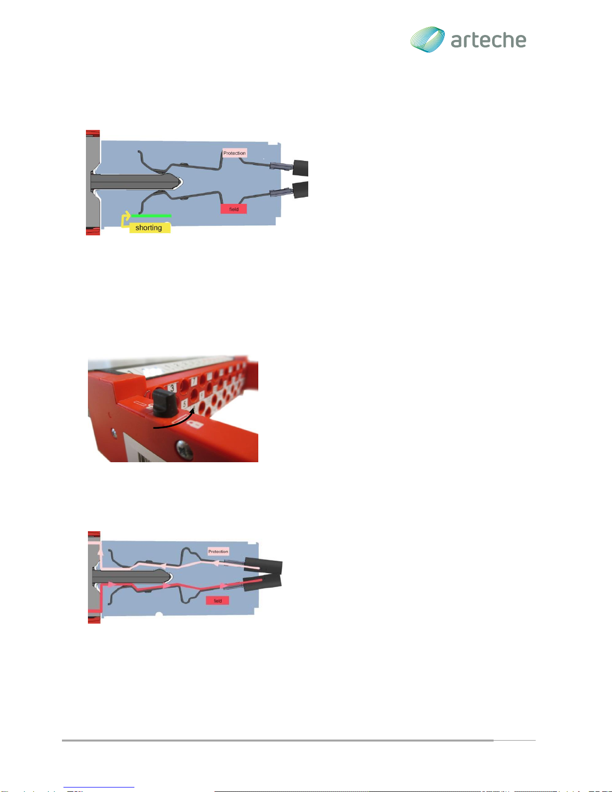
Safe for the user, the user will never have access to live parts during insertion or
extraction of the test plug, and any field connection is located on safety connectors.
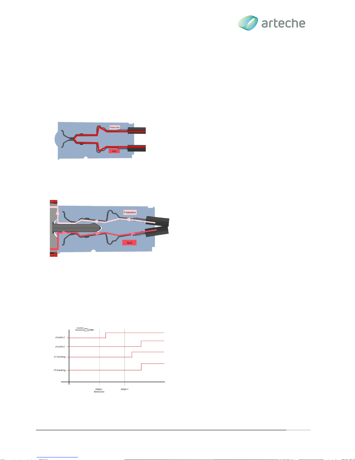
Safe insertion sequence, (make before break). The trip circuits are opened in the
first place, avoiding undesired operation and later on, the voltage and current circuits
are opened, ensuring that transformer circuits are shorted before opening the current
circuits.
Safe extraction sequence, the defined extraction sequence assures to have
enough time to stabilizing the system. The first step connects the voltage and the
current circuits, later on, the user must act specifically on the test plug before being
able to extract it completely.
Unique test plug for different test block configuration for the same number of
circuits (14).
Installation Orientation, there are two options: vertical and horizontal, the user is
able to choose the installation orientation.
Avoid errors in the maneuver: Using the cover plugs available in the plug:, User
errors are avoided blocking access to field voltages and currents.. (plug odd
terminals in case of model 14, terminal pairs in the case of model 14RC) in type
contacts 2, A and B, and / or avoiding the injection of other power sources in type 1
contact. Cover plugs are compatible for all test plug terminals.
Type 1 contacts are referenced to circuits that open in the first phase (trips, signals and
protection power supply).
Type 2 contacts are referenced to circuits that open in the second phase (voltage).
Type A contacts correspond to the current circuits with automatic short-circuited.
Type B contacts are referenced to current circuits with automatic short-circuited, indicating the
end of the shot-circuit group.

SAFETY BASIC MEASURES AND RECOMMENDATIONS
Test Block saTECH TSB-14 | User Manual | Rev.: 2.0
7
Chapter 3. Safety Basic Measures and Recommendations
This manual doesn’t replace the procedures for operation and security that are currently valid
and adopted by electric / operators companies for field installation works. Please read all of the
instructions of this manual before installing the saTECH TSB-14.
Safety symbols:
The following symbols are located on different parts of the equipment and this manual:
Paragraphs marked with this symbol contain information which, if not properly
followed, may cause damage to equipment and / or installation.
Paragraphs marked with this symbol contain information which, if not properly
followed, may cause personal injury or even death.
General Safety instructions:
The installation and operation of the products described in this manual can be made only by
trained personnel who have expertise in substation protection, automation and control.
The test blocks are electrical equipment. Therefore, wrong installation or
wrong connection can lead to malfunction or permanent equipment failure or
equipment connected to it, therefore it is recommended to follow the
instructions listed below:
The assembly of the test block should be done on disconnected and de-
energized wires.
The test block must be connected rigidly to the ground.
Check that the secondary windings of the current transformers are
grounded through one of its terminals.
Check that the connections are correctly tightened and that the contact
surfaces are clean.
Check the correct polarity of the connections.
Check the correct external wiring. The secondary of the current
transformers must be wired to intensity terminals A and B.
Do not disassemble the test block or test plug. Correct installation of
internal parts is critical to warrant the insulation and avoid internal arcs.

PRINCIPLE OF OPERATION
Test Block saTECH TSB-14 | User Manual | Rev.: 2.0
8
The ARTECHE guarantee ceases when, without express authorization of ARTECHE SMART
GRID S.L, external personnel to ARTECHE SMART GRID S.L. makes any changes or
reparation in the product. There are not included the failures by normal use out of the
guarantee period, neither by inappropriate use, carelessness or negligence of the user.
All secondary of a current transformer that is not loaded should be short-
circuited; otherwise, the voltage between open circuit and secondary terminals
can reach dangerous levels, even to destroy the equipment.
It’s absolutely necessary to connect the equipment to earth according with the
information defined on chapter 5.
Test Block has a sticker DANGER which should take into account during
installation.
Chapter 4. Principle of Operation
Test Block Cover
The test block saTECH includes 14 circuits, which can be
accessed by removing the front cover. The front cover
guarantees an IP50 and its removal allows access to the
internal circuitry to enable testing operations. . This
construction guaranteed that you will never be in direct
contact with active parts of the system.
Type of circuits
In the test block there are different types of circuits,
they can be classified as trip, voltage, current or circuits
type contacts 1, 2, A and B respectively.

PRINCIPLE OF OPERATION
Test Block saTECH TSB-14 | User Manual | Rev.: 2.0
9
In the front of the block will be identified by two tag (upper and lower) and in the back will be
associated with the front by Labels with the same legend, where those that are within a circle
will correspond to the field part and those not to the relay part. As a mnemonic rule, the idea of
© circle Field can be used.
Closed Circuit
In normal state the test block circuits are closed contacts.
While the field terminals (identified by numbers inside
circles) connected to transformers and the equipment
(Protection) terminals connected to the equipment.
Open Circuit
The opening of circuits is achieved inserting the
test plug inside the test block. With this
maneuver the field and protection circuits are
pull apart.
Opening sequence (Test Plug Insertion)
During the insertion of the test plug the circuits are ready to be able to test the protection relay,
according to the next ordered sequence:
1. Opening of the trip circuits and signal.
2. Shorting current transformers circuits
3. Open voltage and current circuit.

PRINCIPLE OF OPERATION
Test Block saTECH TSB-14 | User Manual | Rev.: 2.0
10
Current Circuit
It is not required externally short-circuit of the
current transformers in the test plug. The
circuits include a mechanism for ensuring the
short current transformers before proceeding
to open the corresponding contact test block.
Arteche offers the possibility to select from
various types of shorted, depending on the
application. On the front side of the block, you can see which of those circuits are shorted, also
from identification shown on labels frame. This identification is visible even when the test plug
is inserted.
Lock & Unlock Test Plug
Once the test plug is inserted, it can be locked to
prevent involuntary extractions, turning the black buttons
of the test block.
For test plug removal is necessary to unlock it, turning
the two buttons and unlocking the retention
mechanism.
Signal Injection
Once the Test Plug is fully inserted tests signal
injections can be performed with bananas by the
Test Plug. With Test Plug inserted the field
elements are automatically isolate, shorting
current transformers and opening voltage / trip
circuits.
Closing sequence (Test Plug Extraction)
The retention system force to do the extraction of the test plug, with the following sequence:

PRINCIPLE OF OPERATION
Test Block saTECH TSB-14 | User Manual | Rev.: 2.0
11
1. Connect current and voltage circuits
2. Open current transformers short circuit
3. Unlock Test Plug
4. Connect trigger circuits.
Stabilization system in the extraction
In the test plug extraction, before trip circuit
connection, it is necessary to stop and press the
two buttons to unlock the latching mechanism.
This operation will allow voltage and current values
to stabilize after transients during the connection,
and will avoid unwanted tripping during the trigger
circuit connection.
Guided and poka-yoke
The test plug includes a guides and a poka-yoke
system(Prevents improper connections), to make easier
the insertion into the test block in the proper position and
ensuring the opening of all contacts, of the same type
simultaneously.
During test plug insertion and extraction there are not bounces that could
damage current transformers.
Click

PRINCIPLE OF OPERATION
Test Block saTECH TSB-14 | User Manual | Rev.: 2.0
12
During test plug insertion and extraction maneuvers care should be taken to align and insert
properly the test plug in the block, one uniform movement should be done to avoid
misalignment between plug and block.
Reference lines
When the test plug is inserted into the test block, the user should push it until there is no gap
between the test block and the test plug, in order to guarantee that the retention system is
working during the safety extraction operation. To verify this, two lines have been arranged in
the plug. Once they are aligned with the framework of the block, they will help us to check
visually whether the plug is properly inserted or not.
Banana Connection
There are 28 banana plugs in the test plug, which allow the use of safety
banana plugs: 14 banana plugs of 4mm are used for the test injection of
the relay protection, and the other 14 to provide access to field elements.
All the banana plugs of the test plug are identified by a number that
corresponds to the same number in the test block.
In cases where a multiple plug banana connection in series is required, the

PRINCIPLE OF OPERATION
Test Block saTECH TSB-14 | User Manual | Rev.: 2.0
13
use of bent bananas is necessary to avoid the handle of the test plug. From our experience we
recommend using the security strap of the Stäubli Electrical Connectors Multi-Contact Right-
angle adapter XWA-4/19 Ref. 66.9694. Page 71.
Plug Covers
A set of plug plastic covers is supply with the test plug, which is
recommended to place in the plugs where you want to avoid banana
connections. These covers are compatible for all the plugs.
It is advisable to place covers on the circuits that are used for
protection supply, to avoid errors in the protection power supply.
These can be removed if in the protection a new power supply is
required.
These plug covers must be removed or put by qualified personnel.

PRINCIPLE OF OPERATION
Test Block saTECH TSB-14 | User Manual | Rev.: 2.0
14

TECHNICAL DATA
Test Block saTECH TSB-14 | User Manual | Rev.: 2.0
15
Chapter 5. Technical Data
Technical data
Dielectric strength
IEC 60255-27
saTECH
TSB & TSB-P
IEC 60255-5
2kV between input and output contacts
2kV open contacts, test plug inserted
5 kV rms for 1 minute between all terminals
connected together and the ground terminal
2 kV rms for 1 minute between any pair of contacts,
including contacts adjacent
Step current
saTECH TSB
saTECH TSB-P
IEC 60947-7-1
All circuits 20A allow continuously or 400A for 1s
All circuits 10A allow continuously or 250A for 1s.
Maximum operating voltage
saTECH TSB & TSB-P
300 volts ac or dc continuously
IEC 60255
Environmental conditions
Temperature
Storage -25 ° C to + 70 ° C
operation –25°C a +55°C
IEC 60068-2-1 Cold
IEC 60068-2-2 Dry heat
Humidity
IEC 60068-2-78
56 days a 93% Relative Humidity and +40°C
Enclosure protection
IEC 60529-1:
TSB with front cover IP50
TSB without front cover IP20
TSB-P connected IP20
mechanical characteristics
Vibration
60255-21-1 IEC Class II
60255-21-2 IEC Class II
saTECH TSB-14 Rear View

MODEL SELECTION
Test Block saTECH TSB-14 | User Manual | Rev.: 2.0
16
Chapter 6. Model Selection
1-. Horizontal position (Reading from left to right)
* Current circuits to be short-circuited must be placed Contiguously, i.e.:
2-. Vertical position (Reading
from top to bottom)

DIMENSIONS, INSTALLATION AND CONNECTIONS
Test Block saTECH TSB-14 | User Manual | Rev.: 2.0
17
Chapter 7. Dimensions, installation and connections
DIMENSIONS
CUT OUT
TSB-14
Net weight: 1500 gr
Gross weight: 1850 gr
Package: 263 x 230 x 82
TSB-P
Net weight: 500 gr
Gross weight: 720 gr
Package: 263 x 230 x 82

DIMENSIONS, INSTALLATION AND CONNECTIONS
Test Block saTECH TSB-14 | User Manual | Rev.: 2.0
18
Vertical option
ASSEMBLY AND INSTALLATION
There are two options for the installation of theTest Block: horizontally and vertically. The
installation of equipment will be made according to the following indications:
For the basic TSB-14 model (not RC), In the vertical option, the field circuits must be located in
the right side and the numbers / letters disposition will be top down.
In the horizontal option, he same thing happens for each model, the field circuits must be at the
top and the equipment circuits at the bottom.
The connection of the Test Plug is conditioned by the installation of the Test Block, because it
has a poka-yoke for the correct insertion. The TSB-14 model looks like this:
Vertical option
Horizontal option
Horizontal option

DIMENSIONS, INSTALLATION AND CONNECTIONS
Test Block saTECH TSB-14 | User Manual | Rev.: 2.0
19
177.8m
m
51,6mm
Note: The maximum dimensions correspond to the front frame of the block, with the comb inserted or
without it.
Screw and washers: The wiring operation will be performed with the screws supplied
with each equipment.
Tools needed: 6mm hex wrench tube.
Rear connection:
1. Maximum number of ring terminals that can be connected: 2.
2. Cable up to 4mm2 or 12 AWG.
3. Maximum outer diameter of annular connector: 9mm.
4. With block-type tests are supplied Phillips head M4 screws.
5. The maximum torque for the screws is 2.5N.
Earth connection.
After the test block is placed in the cabinet, the earth connection must be made. The
saTECH TSB. Has two earth connections, one of them has to be done, It is not
necessary to ground both ends. The wiring and earth (Din 933 cabeza hexagonal)
connection screw set are included
with the test block. The tool to be
used with grounding screws is a
7mm wrench.
Earth connection

DIMENSIONS, INSTALLATION AND CONNECTIONS
Test Block saTECH TSB-14 | User Manual | Rev.: 2.0
20
CONNECTIONS
The maximum and minimum dimensions of annular connectors recommend to be used in the
back of the test block are:
Table of contents
Other Arteche Test Equipment manuals