Knight UniTech Warewash User manual

0900591 Rev: A (07/04) Page 1 of 24
UniTech Warewash
Instruction Manual

Page 2 of 24 0900591 Rev: A (07/04)
TABLE OF CONTENTS
Specifications ....................................................................................................... 3
Pre-Installation...................................................................................................... 4
Installation
►
Mounting
........................................................................................................4
►
Electrical
........................................................................................................5
►
Plumbing
........................................................................................................7
Operation.............................................................................................................. 8
Programming........................................................................................................ 9
Titration Graphs.................................................................................................. 13
Adding a Sanitizer Pump.................................................................................... 14
Changing the Circuit Board
►
Procedures
................................................................................................... 15
►
Jumper Settings
........................................................................................... 15
Parts Diagrams
►
All Configurations
......................................................................................... 16
►
Liquid Detergent
........................................................................................... 17
►
Dry Detergent (Brass)
................................................................................... 18
►
Dry Detergent (Plastic)
.................................................................................. 19
Wiring Diagrams
►
Single Transformer
....................................................................................... 20
►
Dual Transformer
.......................................................................................... 21
►
European Models
.......................................................................................... 22
Declaration of Conformity...................................................................................23
Warranty Information.......................................................................................... 24
Knight Locations................................................................................................. 24
CAUTION: Wear protective clothing and eyewear when dispensing chemicals or
other materials. Observe safety handling instructions (MSDS) of chemical mfrs.
CAUTION: To avoid severe or fatal shock, always disconnect main power when
servicing the unit.
CAUTION: When installing any equipment, ensure that all national and local
safety, electrical, and plumbing codes are met.

0900591 Rev: A (07/04) Page 3 of 24
Parameters Default Value Range
Pass Code 0000 0 – 9, A – Z
Language English English, Spanish, French, German, Dutch, Italian
Rinse Pump Speed 50% 0%-100% (of full speed)
Rinse Limit 60 0 – 60 sec
Rinse Delay 0 sec 0 – 60 sec
Machine Type DOOR DOOR/CONVEYOR
Rack Time 10 sec 10 – 255 sec
Detergent Mode Probe Probe/Probeless
Detergent Type Liquid Liquid / Dry / Small Tank
Detergent Speed 100% 100% (always runs at full speed)
Detergent Concentration 25 0 — 100 Knight units
Alarm Delay 180 sec 0 – 512 sec
Sani Pump Runs With Rinse Rinse/Detergent
Sani Pump Speed 50% 0%-100% (of full speed)
Initial Detergent Charge 1 sec 1 — 64 sec (Door Mode)
1 — 128 sec (Conveyor Mode)
Detergent Recharge Time 1 sec 0 – 255 sec
Rack Count 0 0 – 65536
Recharge after n Racks 1 1 – 99
Det Feed Limit Off On/Off
SPECIFICATIONS
Pass code does not change when clearing all programmed settings
Rack count has its own menu to allow resetting back to zero
SAFETY SYMBOL EXPLANATIONS
Listed below are explanations of the safety symbols that appear either on the unit, in the instruction manual, or both.
Please familiarize yourself with the meaning of each symbol.
GENERAL CAUTION: This symbol indicates a general safety caution.
SHOCK HAZARD: This symbol indicates that hazardous voltages are inside the
enclosure.
READ MANUAL: This symbol indicates to read the manual for important
instructions and procedures related to safety.

Page 4 of 24 0900591 Rev: A (07/04)
PRE-INSTALLATION
Check all applicable plumbing and electrical codes before installation. This will help to ensure that the system is
installed in safe and suitable manner. A wiring schematic of the dishwasher is useful. This is provided by the
dishwasher manufacturer or may be on the machine itself.
Plan to mount the unit on a nearby wall. Try to keep the unit within three feet from the final rinse line to avoid long
tubing runs. Do not mount the unit in the direct path of steam. This can short-circuit and permanently damage the
unit. Mounting the unit on the side, on the back, or on the vents of the dishwasher may cause thermal overload and
damage the performance of the unit.
If you are going to add a sanitizer pump (optional) to a two-product system, then it should be attached to the unit prior
to installation (see page 14).
Before beginning the installation, make sure you have the following tools and materials ready...
INSTALLATION — MOUNTING
(1) Remove existing dispenser, if any.
(2) Use the mounting bracket to mark where the holes
need to be drilled. Drill the three holes.
(3) Press in the dry wall anchors and mount the
bracket.
(4) Hang the dispenser and mark where the bottom
hole goes.
(5) Drill last hole and press in final dry wall insert. Do
not install the unit on the wall yet.
•Flat and Phillips screwdrivers. One screwdriver needs
to have a long (20 cm) shank to reach the bottom
mounting screw on the dispenser.
•Drill and drill bits.
•18 gauge wire for power, signals, and probe (check
local codes).
•Wire cutters, wire strippers, and pliers.
•Wire terminal connectors and a crimping tool.
•Voltmeter (or multi-meter).
•Dry wall inserts and mounting screws.
•Electrical tape.
•Titration kit.
•Dispenser accessory kit.

0900591 Rev: A (07/04) Page 5 of 24
INSTALLATION — ELECTRICAL
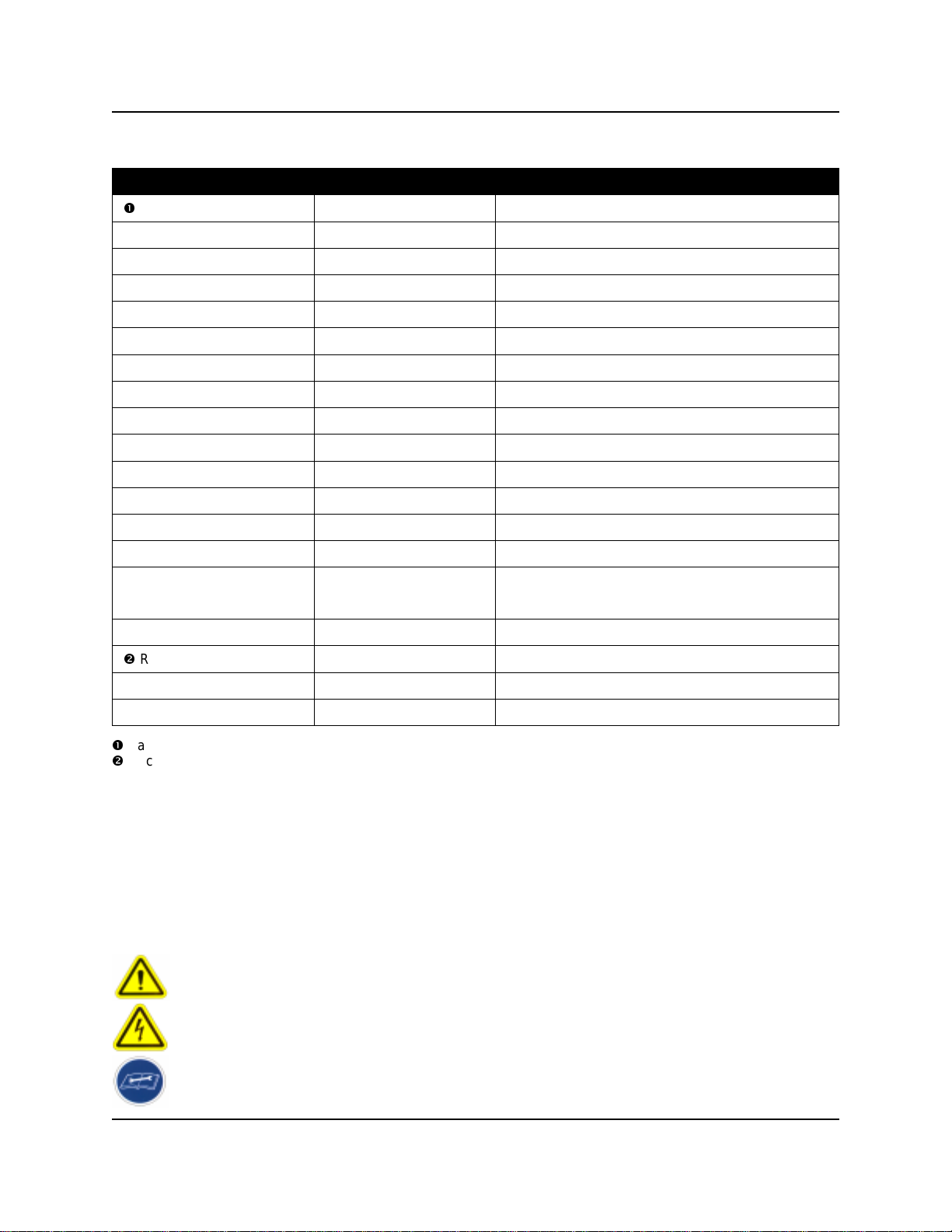
Review the wiring diagrams on pages 20 - 22 to
familiarize yourself with the wiring connections that
apply to the UniTech model you have.
Important note for pre-wired units: These models have
color coded wires for power, signals, and probe. Be sure
to use the correct wires for the following electrical
connections. The transformer connections in these
models are pre-wired for 230V (as shown in the wiring
diagrams). This must be changed inside the unit
prior to installation for 115V or 208V applications!
European models will always be 230V only!
Make sure that all power is off to the dishmachine. Open
the cover and locate an appropriate source for the wash
pump and rinse pump signals, plus a main power
source (for single transformer units). Consult the wiring
diagram for the dishmachine, if available.
Main Power
A main power connection only applies to single
transformer systems (typical). Disregard this section for
dual transformer systems.
Connect leads to a 115, 208, or 230 VAC power source
that is “on” when the dishmachine is “on.” This will
provide power for both detergent and rinse however,
UniTech will only pump chemical when electrically
signaled. Whenever possible, use the dishmachine’s
ON/OFF switch as the main power source. Avoid using
the dishmachine’s washpump motor as main power.
Detergent Signal
A detergent signal is required to either activate the
detergent probe sensing operation, or to trigger
probeless initial charge. A detergent signal is not
normally required when using probeless/door mode, as
the rinse signal is typically used to trigger initial charge.
Check the dishwasher for a power source that is active
during the wash cycle only, for example, the magnetic
contactor that controls the wash pump motor.
•Single transformer: Connect leads to the detergent
signal source. Signal voltage range is 14 - 240 VAC.
•Dual transformer: Connect leads to the detergent
power source (must be 115, 208, or 230 VAC).
Rinse Signal
In addition to running the rinse pump, the rinse power
signal triggers detergent recharge injection if probeless
mode is selected. The rinse signal can also be used to
trigger the detergent initial charge if using probeless/
door mode.
Check the dishwasher for a power source that is active
during the rinse cycle only, for example, the rinse
solenoid or rinse cycle light.
•Single transformer: Connect leads to the rinse signal
source. Signal voltage range is 14 - 240 VAC.
•Dual transformer: Connect leads to the rinse power
source (must be 115, 208, or 230 VAC).
Probe Installation (if required)
Drain the dishmachine if necessary. Install the probe per
the following steps, or replace any existing probe (if
there is one). Use new probe wire in either case.
(1) Install the probe in the wash tank below the water
level. It should be away from incoming water
supplies, near the recirculating pump intake, and 3
to 4 inches from corners, heating elements, or the
bottom of the tank. If an existing mounting hole
cannot be located, cut or punch a 7/8" hole.
(2) Use 18 AWG multi-stranded copper wire for the
probe connection. Avoid running the wire near high
voltage AC lines. Do not route probe wires through
the same conduit as power and signals.
(3) Connect leads to the probe. Ring-type terminals are
recommended (be sure to connect them to the
probe terminals with “backing” nuts to prevent the
probe tips from being pulled out of the probe). The
ring terminals should be secured between the inner
(backing) nuts and outer nuts.

Page 6 of 24 0900591 Rev: A (07/04)
Connecting Power/Signals & Probe to UniTech
Steps 1 - 6 pertain to typical installations, where final
electrical connections must be completed inside the
UniTech dispenser. Disregard steps 1 - 6 for models
that are “pre-wired”.
(1) Ensure that all power sources are turned off before
proceeding with the following steps.
(2) Pull the power and signal wires through the conduit.
Do not route probe wires through the same conduit.
(3) Remove the rinse pump from the left side of the
dispenser to make room. Remove knockout plug for
the conduit by twisting with pliers. Remove
knockout plug for the probe wires. Install wire
grommet for probe wires.
(4) Pull wires through the pump case and into the
control box. Loosen the end of the conduit so that
the male piece can freely rotate. Clearance is tight
in the pump case, and you cannot easily rotate the
conduit nut. Instead, hold the conduit nut with a
wrench and rotate the male piece to tighten.
(5) Disconnect the wiring harnesses to gain easier
access to the wiring terminal strip. The terminal
strip panel can be removed by loosening one screw
(panel is slotted, therefore the screw does not need
to be removed). Slide the panel off the screw and
lift out to access. Strip the wires for power, signal,
and probe (if used) to ¼” bare ends and attach to
the appropriate terminals on the strip. See wiring
diagrams (pages 20 - 22) for further reference.
(6) Re-attach the terminal strip and tighten the screw.
Re-connect all wiring harnesses. Replace rinse
pump and attach faceplate.
(7) When all electrical wiring connections have been
performed, it will be time to hang the dispenser on
the wall. Install the final screw at the bottom of the
dispenser. Use a long shank screwdriver to reach it.

0900591 Rev: A (07/04) Page 7 of 24
INSTALLATION — PLUMBING
Rinse & Sanitizer Plumbing
The following installation steps apply for rinse and
sanitizer pumps alike.
(1) Install the provided 1/4" tube x 1/8" NPT injection
fitting into the side or bottom of the dishwasher
rinse line between the rinse solenoid valves and the
rinse jets. If necessary, drill a 11/32" hole and tap to
1/8" NPT. Use of a saddle clamp may be desired on
copper rinse line for better support.
(2) Cut a suitable length of 1/4" OD poly tubing and
connect between the discharge (right) side of the
pump’s squeeze tube and the injection fitting.
(3) Cut a suitable length of 1/4" OD poly tubing and
connect between the suction (left) side of the
pump’s squeeze tube and the pickup tube provided.
Be sure to draw tubing through the end of the
pickup tube.
(4) Hand-tighten the compression nuts on both the
injection fitting and pickup tube. Plastic ties can be
used to cinch around the connections where the
poly tubing is inserted into the pump’s squeeze
tube.
Liquid Detergent Plumbing
(1) Install the provided bulkhead fitting through a wall
of the wash tank (above water level). If an existing
mounting hole cannot be located, cut or punch a
7/8" hole.
(2) Cut a suitable length of 1/4" OD poly tubing and
connect between the discharge (right) side of the
detergent pump’s squeeze tube and the bulkhead
fitting.
(3) Cut a suitable length of 1/4" OD poly tubing and
connect between the suction (left) side of the
detergent pump’s squeeze tube and the pickup
tube provided. Be sure to draw tubing through the
end of the pickup tube.
(4) Hand-tighten the compression nuts on both the
bulkhead fitting and pickup tube. Plastic ties can be
used to cinch around the connections where the
poly tubing is inserted into the pump’s squeeze
tube.
Dry Detergent Plumbing
(1) A powder or solid type feeder (not provided) should
be used for dispensing dry detergent products.
Follow the instructions included with the detergent
feeder for installation, and recommended water
temperature/pressure.
(2) Cut a suitable length of 1/4" OD copper tubing (not
provided) and connect between the input side of the
water solenoid and the water source. Maximum
recommended water temperature is 140°F (60°C).
(3) Cut a suitable length of 1/4" OD copper tubing (not
provided) and connect between the output of water
solenoid to a powder or solid detergent feeder.
(4) Carefully tighten the compression nuts on the water
solenoid — over tightening may cause solenoid to
leak. Tighten connections to the water source and
detergent feeder as needed.
NOTE: If there is an existing dispenser that uses dry
detergent, examine the power bowl. Make sure it is not
clogged and that the spray pressure is sufficient to
dissolve solid/powder products efficiently. Make sure the
water source is hot water. If necessary, tap into a hot
water line for a new source.

Page 8 of 24 0900591 Rev: A (07/04)
OPERATION
Detergent — Probe Mode
With the detergent signal “on”, the conductivity probe
senses detergent concentration. When concentration
drops below the setpoint, the control automatically turns
on detergent feed. As the detergent feeds, the control
senses the rate at which the detergent concentration is
approaching the setpoint. The control then begins to
pulse feeds to prevent over-use of chemical. The pulse
feed rate will depend on how fast the setpoint is being
approached.
The detergent alarm will sound if the setpoint is not
reached within the alarm delay time period. The alarm
can be temporarily silenced. A “feed limit” feature allows
you to set the unit to automatically shut off the detergent
feed when the alarm has been activated.
Detergent — Probeless Mode
Controls detergent concentration without a probe, based
on timed detergent feed modes. Initial charge time feeds
detergent to bring the dishmachine to working
concentration when initially filled with water. The initial
charge can be activated by a detergent signal, or by the
rinse signal (of 30 seconds duration, or longer) when
using door mode. The initial charge counter will
increment for each activation.
Recharge time feeds detergent to maintain detergent
concentration as rinse water dilutes the dishmachine.
The recharge is triggered after a specified number of
racks passes through the machine.
Rinse Pump
The rinse pump will operate whenever the rinse signal is
energized. The rinse delay feature will postpone the
activation of the rinse pump until the delay time has
expired. The rinse limit shuts down the rinse pump after
the signal has been present for a selected time. Rinse
delay and rinse limit are functional with door machines
only.
Sanitizer Pump
A menu selection sets the sanitizer pump to operate
with detergent feed, or with rinse feed. The sanitizer
pump will run simultaneously with detergent or rinse,
whether using probe or probeless mode, rinse delay or
rinse limit.
BUTTON FUNCTIONS
•ENTER: Holding the enter button for 3 seconds
(approx.) switches between run and program modes.
Enter also advances through programming menus.
•SCROLL: The scroll button moves the position of the
cursor in menus where text or number changes are
done. The scroll button will “wrap around” at the end
of a line of characters, meaning that the cursor will
advance to the beginning of the line automatically.
The scroll button toggles between choices in menus
that have selectable settings. The scroll button also
shows the rack count and initial charge count during
normal operation.
•UP (
): Increases numeric values or advances
upward through available characters. Hold the button
down to rapidly advance. The UP button also acts as
rinse prime during normal operation.
•DOWN (
): Decreases numeric values or advances
downward through available characters. Hold the
button down to rapidly advance. The DOWN button
also acts as sanitizer prime during normal operation.
De-lime Mode
During normal operation, hold the SCROLL and DOWN
buttons simultaneously for 1 full second. When “De-
Lime Mode“ appears on the display, all chemical feed of
the UniTech will be halted. Press the SCROLL and
DOWN buttons again, or cycle main power to the unit, to
exit the de-lime mode. Otherwise, the unit will
automatically exit de-lime mode after 10 minutes.
Alarm Mute
During normal operation, the low detergent alarm
(probe mode) can be silenced by pressing the SCROLL
and UP buttons simultaneously for 1 full second. The
display will show “Alarm Muted” and the audio alarm will
turn off for 5 minutes.

0900591 Rev: A (07/04) Page 9 of 24
PROGRAMMING
You may find it helpful to read through the programming instructions before getting started. This will better familiarize
you with the operation of the UniTech, and will make the actual programming go much quicker. Be aware of the
following notes.
•If you wish to return to normal operating mode at any point during programming, hold down the ENTER button for 3
seconds to exit the programming mode.
•While programming, if no buttons are pressed for approximately 2 minutes, UniTech will automatically return to
normal operating mode.
•Programming changes can be made while UniTech is operating — changes will take effect immediately. This
allows you to make minor adjustments “on-the-fly” and fine tune the performance of your system.
When you’re ready to get started, hold down the ENTER button for about 3 seconds to go into the programming
mode. Release the button when you see the following display...
Continue on next page
If you wish to change the menu language, press SCROLL to advance
through the available choices until your desired language name is shown on
the display. Press ENTER to continue.
SELECT LANGUAGE:
ENGLISH
All new systems are shipped from the factory with the pass code set at 0000.
If the system is new, press ENTER to continue.
If the pass code has been changed from the default of 0000 (explained later
in this manual) use
/
and SCROLL to type in your code, then press
ENTER to continue.
ENTER PASS CODE:
0000 PRESS ENTER
Use
/
buttons to change the speed of the rinse pump. The pump will
begin running when either button is pressed. When the desired setting has
been reached, press ENTER — the pump will stop running, and you will
advance to the next menu.
RINSE SPEED:
50%
You will only see this display if UniTech recognizes that a sanitizer “satellite
pump” is connected. Use
/
buttons to change the speed of the sanitizer
pump. The pump will begin running when either button is pressed. When the
desired setting has been reached, press ENTER — the pump will stop
running, and you will advance to the next menu.
SANITIZ SPEED:
50%
Use the SCROLL button to choose probe or probeless detergent feed mode,
then press ENTER to continue.
DETERGENT MODE:
PROBE_

Page 10 of 24 0900591 Rev: A (07/04)
•If you chose to use PROBE mode, you will see the
following menu... •If you chose to use PROBELESS mode, you will
see the following menu...
Alarm delay is a time frame that the detergent
setpoint is expected to be reached within. If the
detergent setpoint is not achieved within the set
time, the alarm will sound intermittently until the
problem is resolved or power is cycled.
For door machines, this setting should be
calibrated to 5 – 10 seconds shorter than the
washcycle. For conveyor machines, should be
slightly longer than the time it takes for the unit to
achieve the setpoint with a fresh tank of water.
Use
/
to choose from 0 to 512 seconds, then
press ENTER to continue.
ALARM DELAY:
180 SEC
The initial charge feeds detergent to achieve
working concentration when the dishmachine is
initially filled with a fresh tank of water. The
available timing range depends on whether door
or conveyor mode is selected:
DOOR: 1 to 64 seconds
CONVEYOR: 1 to 128 seconds
Use
/
to set the initial charge time, then press
ENTER to continue.
INIT DET CHARGE:
01 SEC
The recharge feeds detergent to maintain the
working concentration as rinse water dilutes the
dishmachine. The available timing range is 0 to
255 seconds.
Use
/
to set the recharge time, then press
ENTER to continue.
DET RECHARG TIME
01 SEC
This setting allows you to choose how many racks
will be counted before triggering the recharge
feed. The range is 1 to 99 racks.
Use
/
to set recharge rack count, then press
ENTER to continue.
NOTE: Ensure that this setting is for 1 rack if
using a two-transformer unit on a door machine.
RECHARGE AFTER
01 RACKS
Detergent concentration is set in Knight Units. A
chart is provided on page 13 to show the
relationship between Knight Units and drops of
titration. Use the chart to determine the number of
Knight Units needed for your desired titration.
Use
/
to choose from 0 to 100 Knight Units,
then press ENTER to continue.
DETER CONCEN:
25 KNIGHT UNITS
This setting allows you to choose if you wish to
see the actual concentration reading on the
display during normal operation. Use SCROLL to
turn the concentration display on or off, then
press ENTER to continue.
DISPLAY DET CONC
ON_
Detergent feed limit works in conjunction with
alarm delay. When this feature is “on”, and the
detergent setpoint is not reached within twice the
alarm delay, the alarm will become continuous
and detergent feed will be halted until the problem
is resolved or power is cycled.
Use SCROLL to turn the feed limit on or off, then
press ENTER to continue.
DETER FEED LIMIT
OFF_
Continue on next page

0900591 Rev: A (07/04) Page 11 of 24
Continue on next page
If you wish to clear the rack counter, press the DOWN button. The display
will briefly flash to the rack counter to verify that it was set back to zero, and
will then return to the display at left. Press ENTER to continue.
‘DOWN’ KEY TO
RESET RACK COUNT
This menu item allows you to change the display name. Press the SCROLL
button once and you will see a screen with the current display name
showing. Use
/
to change the selected character (the one that is
underlined) and SCROLL to advance to the next character. When finished,
press ENTER to continue.
‘SCROLL’ TO CHAN
GE DISPLAY NAME_
This menu item allows you to change the pass code. Use
/
to change the
selected character (the one that is underlined) and SCROLL to advance to
the next character. When finished, press ENTER to continue
CHANGE PASS CODE
0000 PRESS ENTER
If you changed the pass code in the previous menu, you
will be prompted to confirm your choice. If you wish to pick
a different number, press SCROLL to return to the
previous menu, otherwise press ENTER to continue.
ARE YOU SURE?
0000_IS NEW CODE
Use SCROLL to choose door or conveyor as the type of dishmachine in use,
then press ENTER to continue.
MACHINE TYPE:
DOOR_
If you wish to clear the initial charge counter, press the DOWN button. The
display will briefly flash to the counter to verify that it was set back to zero,
and will then return to the display at left. Press ENTER to continue.
DOWN KEY TO RES
INIT CHARGE CNT_
This menu item will only appear if you have chosen probeless mode, and the
door setting as the type of dishmachine. The purpose of this menu item is to
allow the automatic initial charge feature (that is triggered by a rinse signal
longer than 30 seconds) to be disabled. Use the SCROLL button to choose
enabled or disabled, then press ENTER to continue.
NOTE: If the automatic initial charge is disabled, then only a detergent signal
will trigger the initial charge.
AUTO INIT-CHARGE
ENABLED_

Page 12 of 24 0900591 Rev: A (07/04)
Wrap around to first menu item
•If you chose DOOR as machine type, you will see
the following menu... •If you chose CONVEYOR as machine type, you will
see the following menu...
Use SCROLL to choose liquid or dry as the type of detergent, then press
ENTER to continue.
There is also a “SMALL TANK” setting that can be selected for special
applications to enhance dry detergent feed in probe mode (does not apply to
probeless). If SMALL TANK is selected, the detergent feed rate will be more
aggressive when the concentration reading is within 5 Knight units of the
setpoint. Additionally, the detergent alarm (delay) function will be by-passed
when the concentration reading is within 3 Knight units of the setpoint.
DETERGENT TYPE:
LIQUID_
You will be prompted if you wish to reset the system. This function is
recommended for new installations and allows you to clear all memory and
set the unit back to default parameters.
Hold down on the SCROLL and DOWN buttons until you see the message
“RESETTING EVERYTHING“ then release both buttons. After a few
seconds, the memory will be cleared and the display will return to the display
at left. Press ENTER to continue.
SCROLL & DOWN TO
RESET EVERYTHING
Use SCROLL to choose whether you wish to have the sanitizer pump run
(simultaneously) with the rinse pump, or the detergent pump, then press
ENTER to continue.
SANI RUNS WITH:
RINSE_PUMP
This feature will stop the rinse pump after XX
seconds of continuous rinse signal, conserving
rinse agent on door-type dishmachines that fill
through the rinse valve.
Use
/
to choose from 0 to 60 seconds, then
press ENTER to continue.
RINSE LIMIT:
60 SEC
You will be prompted for the rack time. Use a
stop-watch (if available) to clock the time it takes
for one rack to pass through the rinse arm on the
machine. Use
/
to choose from 10 to 255
seconds, then press ENTER to continue.
RACK TIME:
10 SEC
This feature delays the operation of the rinse
pump for a selectable time once the rinse signal
is received. The delay time helps to conserve
rinse agent on door-type dishwashers (using with
conveyor machines is not typical for this feature).
Use
/
to choose from 0 to 60 seconds, then
press ENTER to continue.
RINSE DELAY:
00 SEC
You will only see this display if using probeless
detergent mode. This setting locks out the initial
charge for the time specified (from the previous
initial charge). This prevents over-use of chemical
if the detergent signal energizes unexpectedly
during operation. Use
/
to choose from 0 to
120 minutes, then press ENTER to continue.
INIT CHRG LOKOUT
01 MINUTES

0900591 Rev: A (07/04) Page 13 of 24
UniTech Titration Drops vs. Knight Units
-5
0
5
10
15
20
25
30
35
0 20 40 60 80 100 120
Concen Set Point in Knight Units
Knight Kit Titration Drops
Titration Drops vs. Knight Units Poly. (Titration Drops vs. Knight Units)
UniTech Det Concen(ms) vs. Knight Units
-1
0
1
2
3
4
5
6
7
8
9
0 20406080100120
Knight Units
Concen (ms)
Concen (ms) vs. Knight Units Linear (Concen (ms) vs. Knight Units)

Page 14 of 24 0900591 Rev: A (07/04)
ADDING A SANITIZER PUMP
Adding an optional sanitizer pump to an existing 2-
product system requires just a few simple steps. The
sanitizer pump is normally mounted on the right side (as
you face the unit) of the UniTech dispenser, however
can be mounted on the left side if necessary.
(1) Turn the unit over and lie it down, preferably on a
smooth surface that won’t scratch the display.
(2) Remove the cover on the right-hand side of the unit
by gently prying it up with a flat screwdriver tip.
(3) Line up the sanitizer pump in the slot on the Uni-
Tech. Ensure the 4-pin (bus) connectors are
aligned and slowly slide the pump into place.
(4) Insert the two provided screws and tighten.
(5) Set the DIP switches (back of sani pump) so that
switch #1 is ON and all other switches are OFF.
(6) Process complete! Now ready for mounting.
Display Shown on Power Up
When the UniTech dispenser is powered up for the first time after adding a sanitizer pump, the system will
automatically check for new devices and the following display will appear.
This display shows that UniTech has recognized the sanitizer pump
connected to the bus. The #1 indication simply means that this is the first
“satellite” pump added to the unit. This message will appear briefly, then the
system will automatically advance on to the normal display.
NOTE: A sanitizer pump is the only satellite pump that can be added to a
UniTech warewash unit.
500 PMP Found
Device #1 = Sani

0900591 Rev: A (07/04) Page 15 of 24
CHANGING THE CIRCUIT BOARD
(1) Ensure that power to the unit is off.
(2) Loosen the two screws and swing the cover open.
(3) Remove mounting screw from the center of the
circuit board. Disconnect wiring harnesses and all
remaining wires that attach the circuit board to the
terminal strip. Note the location of wires for later.
(4) Gently push up on the two upper mounting tabs
while pulling the circuit board away from the cover.
Once the top is loose, the bottom will pull away
freely from the lower tabs.
Jumper Settings
The circuit board has shunt jumpers that must be set
according to the transformer configuration of your
UniTech system (diagram to the right shows jumper
locations). This is particularly important when changing
circuit boards so the new board will work correctly.
(5) Replace with new circuit board and carefully line up
the buttons and LED’s with the holes on the cover.
Snap the board into place on the upper and lower
mounting tabs. Set the jumpers per table below.
(6) Re-connect all wires to the terminal strip (that were
disconnected in step 3) and re-connect the wiring
harnesses. Replace the mounting screw.
(7) Carefully tuck all wires in while closing the cover.
Tighten the cover screws.
(8) Process complete! Now ready to be powered up.
Transformers JP1 JP2 JP3 JP4
Single (1) xfmr OFF OFF ON ON
Dual (2) xfmrs ON ON OFF OFF
JP1
JP2
JP3
JP4
UNITECH CIRCUIT BOARD

Page 16 of 24 0900591 Rev: A (07/04)
PARTS DIAGRAM — ALL CONFIGURATIONS

0900591 Rev: A (07/04) Page 17 of 24
PARTS DIAGRAM — LIQUID DETERGENT

Page 18 of 24 0900591 Rev: A (07/04)
PARTS DIAGRAM — DRY DETERGENT
Brass Solenoid Model

0900591 Rev: A (07/04) Page 19 of 24
PARTS DIAGRAM — DRY DETERGENT
Plastic Solenoid Model

Page 20 of 24 0900591 Rev: A (07/04)
WIRING DIAGRAM — 1 TRANSFORMER
Table of contents
Other Knight Dispenser manuals