Knight SANI-CLEAN III User manual

0900456 Rev: G (ECO 6537) Page 1 of 4
INTRODUCTION
The Knight Sani-Clean III is the perfect dispensing system for supermarket meat rooms, kitchen areas, bakeries,
seafood stores, auto dealers, truck washing, loading docks, etc. The Knight Sani-Clean III is the economical system
for controlling cleaning costs. Chemicals are mixed accurately and consistently at your chosen dilution ratio, utilizing
two in-line venturi valves. Up to 16 different product concentrations are available using “screw-in” metering tips.
INSTALLATION
(1) Mount the unit to the wall using the screws and anchors provided.
(2) Mount the hose bracket to the wall using the screws and anchors provided.
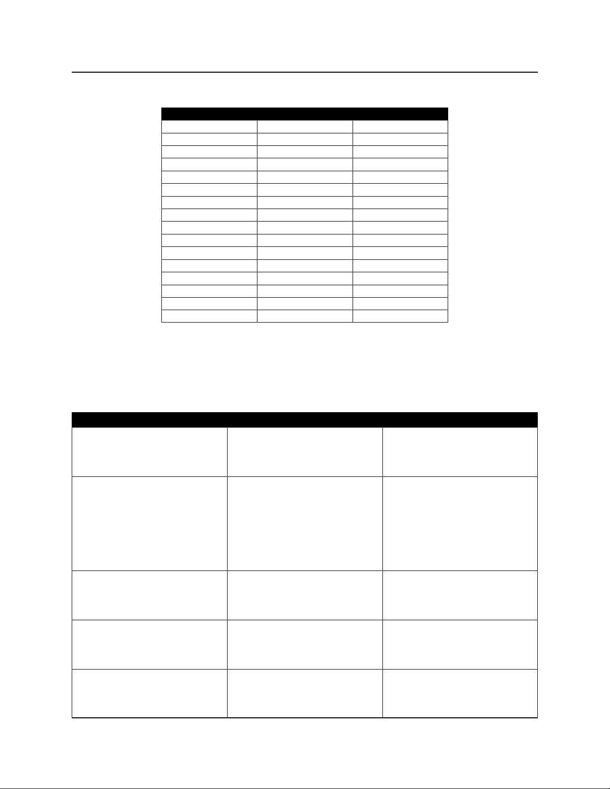
(3) Select the appropriate metering tip (see chart on the following page) and screw into
end of barb fittings. The cover does not need to be removed to access the barb
fittings.
(4) Install foot strainer on the end of each supply tube. Slide a ceramic weight over
each supply tube, then connect the tube onto the barbed fittings. Cinch a plastic tie
wrap (provided) around the connection to secure. Insert foot end into container.
(5) Connect to a water supply using the provided 3/4" garden hose adapter on the left
side of the unit — the adapter can be removed to permit hard plumbing directly to
3/8" or 1/2" NPT water line. Water pressure should be 30 to 80 PSI. Water
temperature should not exceed 140 degrees (F).
(6) Attach the nozzle to the end of the output hose, then connect the hose to the fitting on the bottom of the
unit.
OPERATION
(1) Turn on desired supply valve, Detergent, Rinse, or Sanitizer, and depress spray nozzle handle. The selected
product and water mixture will be dispensed.
(2) To use the Foam feature, attach the Foam Wand to the quick-connect coupling on the end of the nozzle (be sure
air intake holes are not obstructed) and depress spray nozzle handle.
IMPORTANT NOTES
ONLY USE A HOSE AND SPRAY NOZZLE SUPPLIED BY KNIGHT LLC.
DO NOT ADJUST THE KNOB ON THE SPRAY NOZZLE FROM THE FULL SPRAY POSITION.
DO NOT OPERATE MORE THAN ONE PRODUCT VALVE AT A TIME, AS PRODUCT DILUTION RATES WILL
NOT BE ACCURATE.
UNIT SUPPLIED WITHOUT A BACKFLOW PREVENTION DEVICE. TO PREVENT POSSIBLE CHEMICAL
BACKUP INTO THE WATER SUPPLY, COMPLY WITH ALL LOCAL PLUMBING CODES AND INSTALL AN
APPROPRIATE BACKFLOW PREVENTION DEVICE.
SANI-CLEAN III
INSTRUCTION MANUAL
Step 6
Step 5

Page 2 of 4 0900456 Rev: G (ECO 6537)
TIP COLOR RATIO OZ/GAL
No Tip 15 :1 8.0
White 15 :1 8.0
Yellow 15 :1 7.8
Pink 16 :1 7.4
Dk Green 19 :1 6.4
Black 24 :1 5.1
Brown 30 :1 4.2
Gray 37 :1 3.4
Blue 43 :1 2.9
Red 54 :1 2.3
Peach 88 :1 1.4
Lt Blue 147 :1 0.9
Purple 210 :1 0.6
Lt Green 307 :1 0.4
Orange 570 :1 0.2
Lt Brown 0.1999 :1
METERING TIP RATIOS
PROBLEM POSSIBLE CAUSE REMEDY
No output (1) Water supply is off
(2) Product valve is off (1) Turn water supply on
(2) Turn appropriate valve on
Product is not drawn from container (1) Footvalve obstruction
(2) Clogged metering tip
(3) Water inlet blocked
(4) Low water pressure
(5) No product in container
(6) Supply tube is loose
(7) Hose nozzle not fully open
(1) Clean or replace
(2) Clean or replace
(3) Check/clean screen
(4) Must be 30 PSI minimum
(5) Re-fill or use new container
(6) Tighten or replace tie wrap
(7) Fully squeeze nozzle to open all
the way
Too much, or too little product is
drawn Incorrect metering tip Choose the next closest ratio from
chart and verify results — repeat this
step as necessary until the correct tip
is chosen
No water (or very low flow) (1) Obstruction at inlet screen area
(2) Low water pressure
(3) Scaled or clogged fittings
(1) Clean obstruction/replace screen
(2) Use a more suitable source
(3) Clean scaling or free obstructions
Supply container fills with water Checkvalve clogged Clean or replace checkvalve
NOTE: The above chart is based upon the chemical viscosity of water (CPS = 1.0) and should only be used as a
guide — the values were derived using water as the working fluid and 40 PSI dynamic input pressure. Actual ratios
and flow rates may vary due to product viscosity, flow pressure, and tubing distance(s).
TROUBLESHOOTING

0900456 Rev: G (ECO 6537) Page 3 of 4
PARTS DIAGRAM

Page 4 of 4 0900456 Rev: G (ECO 6537)
DISCLAIMER
Knight LLC does not accept responsibility for the mishandling, misuse, or non-performance of the described items
when used for purposes other than those specified in the instructions. For hazardous materials information consult
label, MSDS, or Knight LLC. Knight products are not for use in potentially explosive environments. Any use of our
equipment in such an environment is at the risk of the user, Knight does not accept any liability in such
circumstances.
WARRANTY
All Knight controls and pump systems are warranted against defects in material and workmanship for a period of
ONE year. All electronic control boards have a TWO year warranty. Warranty applies only to the replacement or
repair of such parts when returned to factory with a Knight Return Authorization (KRA) number, freight prepaid, and
found to be defective upon factory authorized inspection. Bearings and pump seals or rubber and synthetic rubber
parts such as “O” rings, diaphragms, squeeze tubing, and gaskets are considered expendable and are not covered
under warranty. Warranty does not cover liability resulting from performance of this equipment nor the labor to
replace this equipment. Product abuse or misuse voids warranty.
FOOTNOTE
The information and specifications included in this publication were in effect at the time of approval for printing. Knight
LLC reserves the right, however, to discontinue or change specifications or design at any time without notice and
without incurring any obligation whatsoever.
KNIGHT LLC
(www.knightequip.com)
Knight Headquarters
Tel: 949.595.4800
Fax: 949.595.4801
Knight Canada
Tel: 905.542.2333
Fax: 905.542.1536
Knight Europe
Tel: 0044.1323.514855
Fax: 0044.1323.514828
Knight N. Asia
Tel: 82.2.3481.6683
Fax: 82.2.3482.5742
Knight S. Asia
Tel: 65.6763.6633
Fax: 65.6489.6723
Other Knight Dispenser manuals