Knudson KR Series Manual

9/27/2005 VERSION 4.0 1
KR-SERIES (KR-56A, KR-50A, KR-60A)
Gutter Forming Machines
GENERAL OPERATING AND MAINTENANCE INSTRUCTIONS
Knudson Mfg., Inc.
10401 W. 120th Ave.
Broomfield, CO 80021
USA
(303) 469-2101 (tel) Version: 4.0
(303) 469-7994 (fax) Date: 12/02

9/27/2005 VERSION 4.0 2
Change Record Page:
Document: KR-SERIES Manual
Date Change Authorization
12/02 Updated with solidworks models MCD

9/27/2005 VERSION 4.0 3
TABLE OF CONTENTS
1. PROFILE SPECIFICATIONS.......................................................................................4
2. MACHINE SPECIFICATIONS ..................................................................................14
3. TERMINOLOGY ........................................................................................................18
4. REQUIRED TOOLS AND EQUIPMENT..................................................................20
5. INSTALLATION ........................................................................................................21
6. SETUP AND OPERATION ........................................................................................25
7. ADJUSTMENT AND TROUBLESHOOTING..........................................................34
8. CHANGEOVER PROCEDURES ...............................................................................44
9. MACHINE MAINTENANCE.....................................................................................48
10. TRANSPORT AND MOVING .................................................................................50

9/27/2005 VERSION 4.0 4
1. PROFILE SPECIFICATIONS
1.1. PROFILE SPECIFICATIONS
1.1.1. Profiles
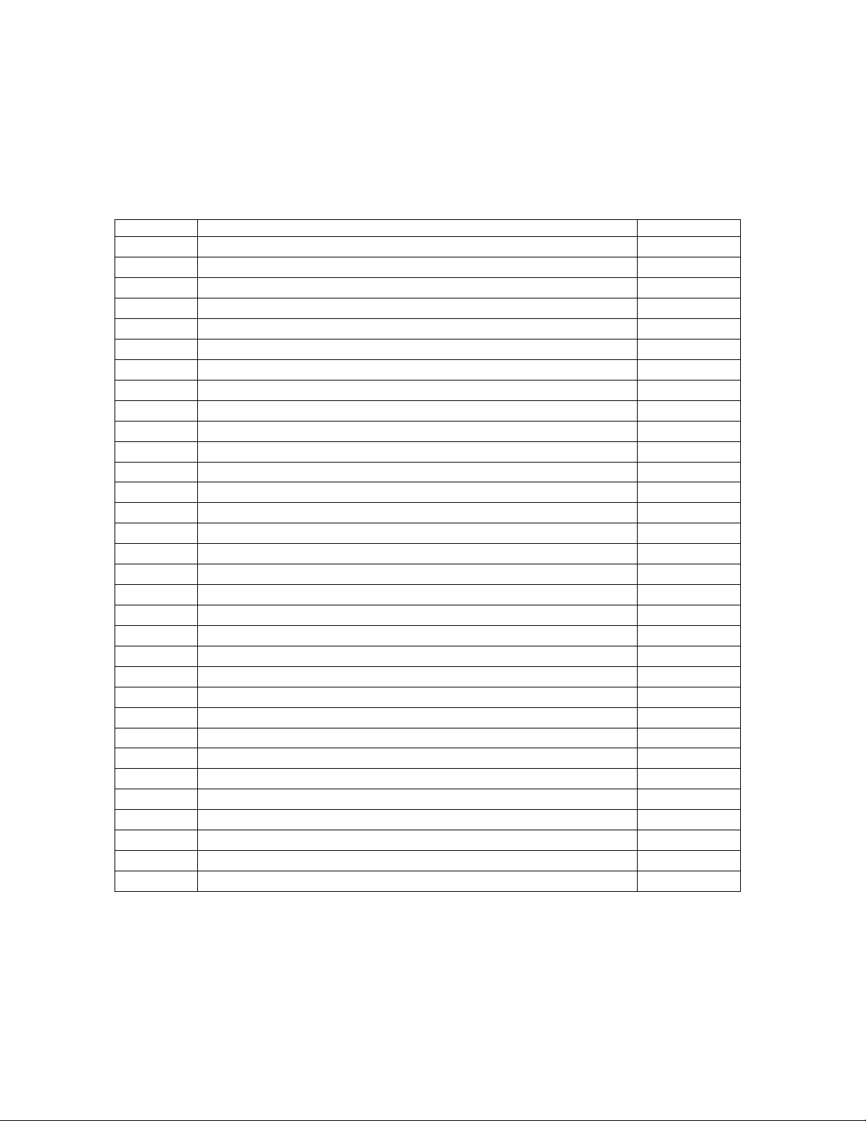
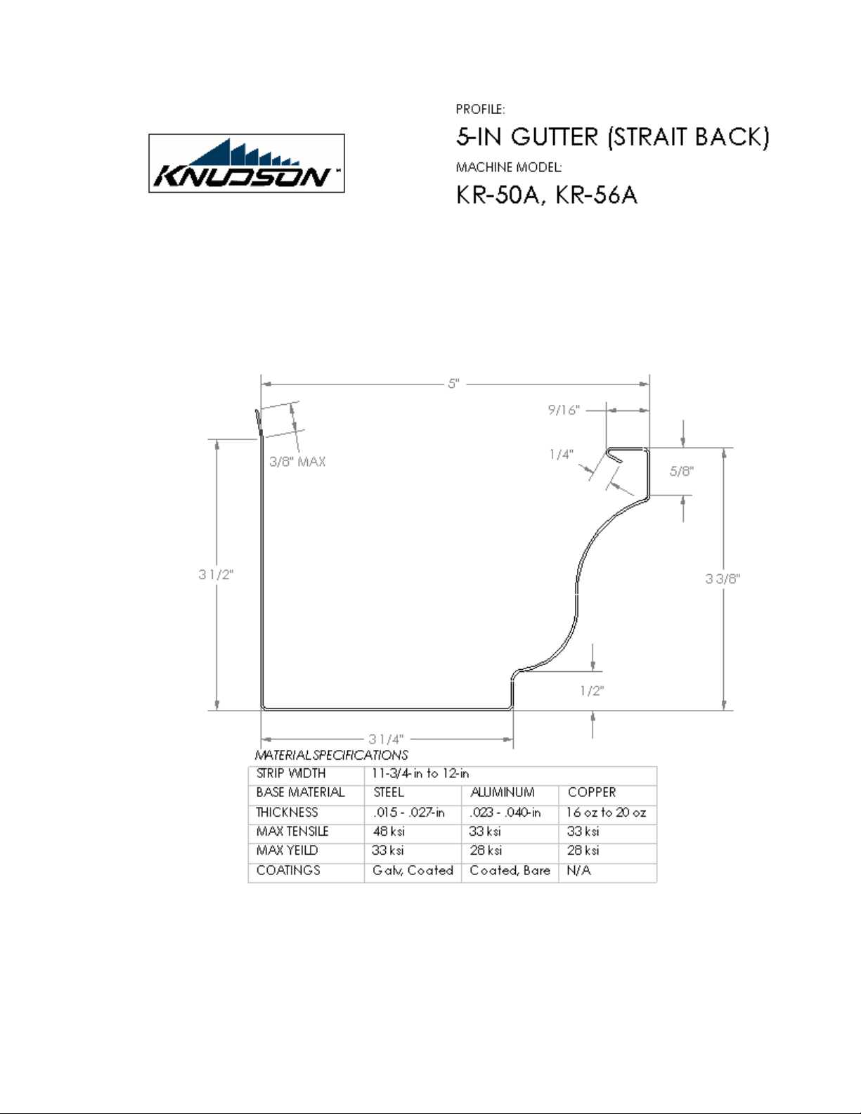
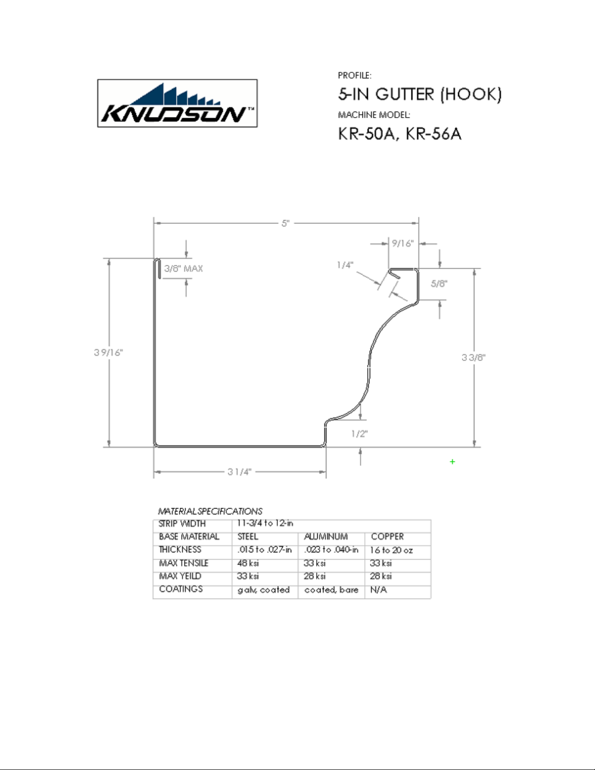
Refer to the enclosed profile drawings at the end of this Section:
5-in K-Style OG Gutter with Straight Back (KR-50A, KR-56A)
5-in K-Style OG Gutter with Free Float Hook (KR-50A, KR-56A)
5-in K-Style OG Gutter with 1-in Flange (KR-50A, KR-56A)
6-in K-Style OG Gutter Straight Back (KR-60A, KR-56A)
6-in K-Style OG Gutter with Free Float Hook (KR-60A, KR-56A)
6-in K-Style OG Gutter with 1-in Flange (KR-60A, KR-56A)
6-in K-Style OG Gutter with 2-in Flange (KR-60A, KR-56A)
1.1.2. Material Types
Steel, Galvanized Steel, Pre-finished/Coated Steel
Aluminum, Coated Aluminum
Copper
1.1.3. Material Thickness
Steel - .015-in (.38mm) to .027-in (.68mm)
Aluminum - .023-in (.57mm) to .040-in (1.02mm)
Copper - 16oz (.53mm) to 20oz (.69mm)
1.1.4. Material Strength
STEEL
Maximum Tensile Strength = 48 ksi (330 MPa)
Maximum Yield Strength = 33 ksi (230 MPa)
(ASTM A611 Grade C or equivalent)
ALUMINUM/COPPER
Maximum Tensile Strength = 33-ksi (227-Mpa)
Maximum Yield Strength = 28-ksi (193-Mpa)
1.1.5. Strip Width (Stretch-Out)
11 ¾-in (298mm) to 12-in (304mm) [5-in profiles]
15-in (381mm) [6-in profiles]
1.1.6. Profile Dimensions
Refer to the enclosed profile drawings at the end of this Section. All shown dimensions are nominal profile
dimensions.

9/27/2005 VERSION 4.0 5

9/27/2005 VERSION 4.0 6

9/27/2005 VERSION 4.0 7

9/27/2005 VERSION 4.0 8

9/27/2005 VERSION 4.0 9

9/27/2005 VERSION 4.0 10

9/27/2005 VERSION 4.0 11

9/27/2005 VERSION 4.0 12
2. SAFETY FEATURES
2.1. GENERAL SAFETY RULES
Read and understand entire Operator’s Manual prior to use of this machine.
The operator should stay alert and use common sense when operating this and any machine. The operator
should not use machine while tired or under the influence of drugs or alcohol.
Proper dress is recommended. Steel toe boots are recommended. No loose clothing or jewelry. Long hair,
loose clothing, and gloves should be kept away from all moving parts. Keep the handles dry, clean, and
free of oil and grease.
Do not operate without safety glasses and leather gloves.
Do not operate without adequate training.
2.2. ELECTRICAL SAFETY
Grounded tools must be plugged into a properly installed and grounded outlet. Never remove the
grounding prong or modify the plug in anyway. Do not use any adapter plugs. Consult with an electrician
to ensure that an outlet is properly installed and grounded.
Avoid body contact with grounded surfaces. There is an increased risk of electric shock if ones body is
grounded.
Water entering a machine will increase the risk of electric shock. If operating the machine in damp
conditions cannot be avoided, use a Ground Fault Circuit Interrupter to supply the power to your machine.
Electrician’s rubber gloves and footwear will further enhance operator safety.
Do not abuse electrical cords. Keep the cords away from heat, oil, sharp edges, or moving parts. Do not
use damaged cords as they increase the risk of electric shock. Outdoor operation of this machine requires
the use of an extension marked “W-A” or ”W”. These cords are rated for outdoor use and reduce electric
shock risk.
Do not operate in gaseous or explosive atmosphere.
*DISCONNECT MACHINE FROM POWER SOURCE WHEN NOT IN USE OR WHEN
SERVICING *
2.2. MACHINE SPECIFIC SAFETY FEATURES
These machines are designed to roll and form sheet metal. During the rolling process, there is the potential
to get ones fingers, hands, toes, and feet pinched between the rollers or other drive mechanisms. Injury
could result if one is not careful enough. Use extreme caution at all times when operating this machine.
Keep others clear of the area of operation.
If the machine crashes (see Section 11), use extreme caution when clearing the crash. A crash presents a
potentially hazardous situation for the machine operator. Crashes often produce sharp, jagged metal edges
that ultimately require handling. Suitable hand and eye protection, to include leather gloves and safety
glasses, should always be worn when clearing a crash.

9/27/2005 VERSION 4.0 13
2.2.1. Safety Features
Item Name QTY Part Number
Emergency Stop Button 1 ELES-0B63
Top Front Cover 1 0050704
Top Rear Cover 1 0050703
Motor Cover, Top 1 0050702
Motor Cover, Side 1 0050705
Die Cover 1 0052326
Caution Sticker 2 STKR-IBOP
Four safety covers, combined with the design of the machine itself, completely encase the drive
mechanisms of this machine. This prevents both the operator and foreign objects from being introduced
into moving machine components.
There is an Emergency Stop button located at the entry end of the machine on the right side. Pressing the
E-stop button will cut power and material will stop moving through the machine.
If the CE control package is ordered, the control panel itself has an extra emergency stop button that
performs the same function as the entry end button.
*This machine should not be operated without the covers in place. *
Despite the presence of safety features, this machine does have semi-exposed cutting devices.
If the parts the stickers have been placed on need to be reordered for some reason, the stickers will come
attached to the parts. Do not use machine without these warning labels.

9/27/2005 VERSION 4.0 14
3. MACHINE SPECIFICATIONS
3.1. MACHINE SPECIFICATIONS – MECHANICAL SYSTEMS
3.1.1. Basic Machine Specifications
Length = 136-1/2-in (3467mm) (with Rack Shear)
Width = 26-in (660mm)
Height = 24-in (610mm)
* Weight (base machine) = 1685-lbs (766-kg)
Height (Including Uprights) = 35-in (889mm)
Height (Including Spool) = 51-in (1295mm)
*Note: Refer to the data sheet at the end of this Section for all weight specifications.
3.1.2. Roll-forming Details
8 powered roll-forming stations
5-station auxiliary box unit (5-in profiles)
4-station auxiliary box unit (6-in profiles)
3.1.3. Production Speed
+50 ft/min (+15 m/min) nominal production speed (60 Hz Electric Motor @ 1725 rpm)
+41 ft/min (12.5 m/min) nominal production speed (50 Hz Electric Motor @ 1425 rpm)
3.1.4. Drive Train
Power Source - Electric Motor
Power Take off - Synchronous Gear Belt Drive
Drive/Forming Rollers - Gear/Sprocket/Roller Chain Drive
Main Drive Speed – 65 rpm @ Ø3.00 Drive Diameter (60 Hz Electric Motor @ 1725 rpm)
Main Drive Speed – 54 rpm @ Ø3.00 Drive Diameter (50 Hz Electric Motor @ 1425 rpm)
3.1.5. Shear Assembly (Cut-off Shear)
5-in Manually Operated Rack and Pinion Guillotine Shear (Rack Shear) (KR-50A, KR-56A)
6-in Manually Operated Rack and Pinion Guillotine Shear (Rack Shear) (KR-60A, KR-56A)
5-in Circular Cam Shear Assembly (KR-50A, KR-56A)(Optional)
6-in Circular Cam Shear Assembly (KR-60A, KR-56A)(Optional)
3.1.6. Coil Handling Equipment
Double Uprights
Single Combination Spool (16-in I.D.)
16-in ID Combo Spool (Optional)
Triple Uprights (Optional)
6-in Coil Cradle (Optional)
5-in Coil Cradle (Optional)
Double Cradle Uprights (Optional)

9/27/2005 VERSION 4.0 15
3.1.7. Airborne Noise Emissions
Equivalent continuous A-weighted sound pressure level = less than 70 dB (A)
3.2. STANDARD MACHINE SPECIFICATIONS – ELECTRICAL/CONTROL SYSTEMS
3.2.1. Electrical Power System
3.2.1.1. Standard Package
- Line Voltage = 100-115 Volts AC / 200-230 Volts AC (+/- 10%)
- Line Current = 15 Amps
- Line Frequency = 60 / 50 Hz (+/- 1%)
- Line Phase = 1φ(single phase)
- Full Load Current = 12.6-14.2 Amps / 6.3-7.1 Amps
- Fuse Rating = N/A
- Electrical Drawing = 005-00-02
- Electrical Enclosure IP Rating = N/A
3.2.1.2. CE Certification Package (KR-50A, KR-60A, KR-56A) (Optional)
- Line Voltage = 100-115 Volts AC / 200-230 Volts AC (+/- 10%)
- Line Current = 15 Amps
- Line Frequency = 60 / 50 Hz (+/- 1%)
- Line Phase = 1φ(single phase)
- Full Load Current = 12.6-14.2 Amps / 6.3-7.1 Amps
- Fuse Rating = 5 Amps
- Electrical Drawing = 005-00-01
- Electrical Enclosure IP Rating = IP4X
3.2.2. Control System
Directional Control/Electric Motor Control: Three- (3) position drum switch (red handle)
Direction Selector Switch, Jog/Stop/Run Switch, Jog Push Button, E-Stop Switch (Optional CE Package)
3.2.3. Safety Features
E-Stop Switch
Top and Side Covers
Spool Locks
Additional E-Stop Switch (part of optional CE Package control panel)
3.3. MACHINE SPECIFICATIONS – OPERATING ENVIRONMENT
The machine will operate correctly under the following environmental conditions:
3.3.1. Ambient Air Temperature Range
+41 to +131°F (+5 to +55°C)
Up to 24 hours at 122°F (50°C)
3.3.2. Humidity Range
30% to 95% Relative Humidity (non-condensing)

9/27/2005 VERSION 4.0 16
3.3.3. Altitude Range
Up to 10,000 feet (3,000 meters)
3.3.4. Vibration, Shock, and Bump
The machine will perform correctly under conditions normally associated with vehicular transport on
maintained roads. Off-road transportation (to include non-maintained roads) may result in incorrect
machine operation.
3.3.5. Transportation and Storage
-13 to +131°F (-25 to +55°C)
Up to 24 hours at +158°F (+70°)
3.3.6. Explosive Atmosphere
The KR-Series Gutter Forming Machine is not designed for use in any type of explosive atmosphere. The
machine should not be operated in an explosive atmosphere of any kind.
3.4. OPTIONAL MACHINE ACCESSORIES
Run-out Stands
Free Float Hook Assembly
1-in Flange Assembly
2-in Flange Assembly
Footage Counter (Imperial or Metric Units)
3.5. INTENDED USE
The KR-SERIES Gutter Forming Machines are intended to form the aforementioned specific profiles from
the designated material specifications. The machines are in no way intended for any other purpose. Any
attempt to use the machines for different purposes may result in serious personal injury or significant
damage to the machines. In particular, the machines are not intended to form partial or different profiles;
not intended to run unspecified material thicknesses or widths, not intended for use as straightening or
flattening devices; not intended for use as any sort of winding, coiling, or uncoiling mechanisms.

9/27/2005 VERSION 4.0 17
Data Sheet
MACHINE/ACCESSORY WEIGHT SPECIFICATIONS
Item Weight (lbs) Weight (kg)
Base Machine 1685-lbs 766-kg
Machine Entry End Cover 7-lbs 3.2-kg
Machine Exit End Cover 18-lbs 12.7-kg
Machine Motor Cover 15-lbs 6.8-kg
5-in Rack and Pinion Shear 29-lbs 13.2-kg
6-in Rack and Pinion Shear 40-lbs 18.2-kg
5-in Cam Shear 28-lbs 12.7-kg
6-in Cam Shear 28-lbs 12.7-kg
5-in Skate Roller (back) 6-lbs 2.7-kg
6-in Skate Roller (back) 9-lbs 4.1-kg
5-in Box Unit 25-lbs 11.4-kg
6-in Box Unit 48-lbs 21.8-kg
Free Float Hook Assembly 18-lbs 8.2-kg
1-in Flange Assembly 21-lbs 9.5-kg
2-in Flange Assembly 23-lbs 10.5-kg
Bead Attachment Unit 20-lbs 9.1-kg
16-in ID Combo Spool 75-lbs 34.1-kg
20-in ID Combo Spool 100-lbs 45.5-kg
Double Uprights 45-lbs (each side) 20.5-kg
Triple Uprights 60-lbs (each side) 27.3-kg
5-in Coil Cradle 50-lbs 22.7-kg
6-in Coil Cradle 60-lbs 27.3-kg
Double Cradle Uprights 85-lbs 38.6-kg
Tool Box (empty) 33-lbs 15.0-kg
Tool Box (full) 110-lbs 50.0-kg
Run-out Stands 15-lbs 6.8-kg

9/27/2005 VERSION 4.0 18
4. TERMINOLOGY
4.1. MACHINE NOMENCLATURE
Entry end - the end of the machine into which the material is fed, the end with the black curved guides;
also called the front end or feed end
Exit end - the end of the machine from which the finished gutter profile emerges, the end with the shear;
also called the rear end or discharge end
Forming rolls - the rotating contoured dies used to both drive the material through the machine and form
the finished gutter profile; also called forming dies, rolling dies, rollers
Left side - when viewing from the entry end of the machine, the side located to the left
Right side - when viewing from the entry end of the machine, the side located to the right. Also called the
“Box Side.”
Station # - forming stations are numbered sequentially from the entry end to the exit end of the machine
Crash – a condition in which any of the following problems may exist:
• metal will not move through the machine
• metal is bent or crumpled against a fixed component in the machine
• metal is bunching up between forming stations
• the drive train is seized
4.2. PROFILE SPECIFIC TERMS
The profile is normally described as if it were being viewed from the entry end of the machine as the
material runs:
Away from the house - profile is horizontally level, but curves toward the front, or box side, of the gutter
Into the house - profile is horizontally level, but curves toward the back side of the gutter
Downhill - the profile runs laterally strait, but curves downward as it exits the machine; also referred to as
having a crown in the profile
Uphill - the profile runs laterally strait, but curves upward as it exits the machine
Left - the profile is horizontally level, but curves to the left as it exits the machine
Right - the profile is horizontally level, but curves to the right as it exits the machine
Twist - one end of the profile rotates away from the other end
4.3. MATERIAL/COIL RELATED TERMS

9/27/2005 VERSION 4.0 19
Camber - lateral curvature in coil stock - camber may lead to an inconsistent profile
Coil Set - longitudinal curvature induced in coil stock due to the winding or coiling process - excessive coil
set may cause rippling in the gutter profile
Edge wave - a ripple-like effect on the edge of the material - often caused by the slitting process
Gauge - term used to reference the thickness of steel material per AISI thickness tolerance ranges - ex: 24
Ga = .0276" thick
Long-centered - center of the coil stock strip slightly longer than the edges - often results from the
annealing process
Oil canning - a periodic pattern of buckling appearing on flat sections of a profile - often results from coil
set
Width - the lateral width of coil stock material - also called strip width or stretch-out

9/27/2005 VERSION 4.0 20
5. REQUIRED TOOLS AND EQUIPMENT
5.1. HAND TOOLS
5.1.1. Combination or Open End Wrenches
½-in, 9/16-in, ¾-in, 15/16-in, 1-1/8-in
5.1.2. T-Handle Hex Wrenches
5/32-in, 3/16-in, 7/32-in, ¼-in, 5/16-in, 3/8-in
5.1.3. L-Handle Hex Wrenches
5/32-in, 3/16-in, ¼-in, 5/16-in
(Ball Nose L-Handle Hex Wrenches Recommended)
5.1.4. Tin Snips
Right Hand, Strait, or Left Hand Snips
(All Three Recommended)
5.1.5. Feeler Gauge
5.2. ELECTRICAL EQUIPMENT
5.2.1. Electrical Generator/Power Source
4500 Watt (4.5 kW) minimum
5.2.2. Extension Cord
#12 AWG 3-wire extension cord with grounded connector - maximum length 100 feet.
5.3. LIFTING EQUIPMENT
5.3.1. Mounting the Machine
The basic machine weighs approximately 1685-lbs (766 kg). The Manufacturer recommends using a lift
with a safe operating capacity of at least 2000-lbs (900-kg) when mounting or moving the machine. Lifting
equipment may include forklifts, overhead cranes, or cherry pickers. Remove all coils/spools prior to any
lifting or moving operation. Coils/spools should be lifted separately.
5.3.2. Loading Spooled Coil
The maximum recommended coil size for any one set of spool uprights or cradle is 500-lbs. Lifting
equipment for loading spooled coil should be able to easily handle 1.25 times the maximum coil size for
reliability and safety.
This manual suits for next models
3
Table of contents