Kobalt 59725 User manual

1
Serial Number Purchase Date
Questions, problems, missing parts? Before returning to your retailer, call our
customer service department at 1-888-3KOBALT (1-888-356-2258), 8 a.m - 8 p.m., EST,
www.lowespartsplus.com.
ATTACH YOUR RECEIPT HERE
ITEM #3832633
MODEL #59725
30.5-IN 3-DRAWER
UTILITY TOOL CART
Español p. 12
KOBALT and logo design are trademarks or
registered trademarks of LF, LLC. All rights reserved.
AS21264

2
PRODUCT SPECIFICATIONS
TABLE OF CONTENTS
COMPONENTS SPECIFICATIONS
Maximum load for small drawer
Maximum load for middle drawer
Maximum load for big drawer
Maximum load for bottom tray
Maximum load for top tray
Maximum total load
50 lbs.
50 lbs.
100 lbs.
100 lbs.
100 lbs.
400 lbs.
Package Contents...........................................................................................................................3
Hardware Contents..........................................................................................................................4
Safety Information...........................................................................................................................4
Preparation.....................................................................................................................................5
Assembly Instructions......................................................................................................................6
Operating Instructions.....................................................................................................................9
Care and Maintenance..................................................................................................................10
Warranty........................................................................................................................................10
Replacement Parts List..................................................................................................................11

PACKAGE CONTENTS
3
A
B
C
D
D
A
B
C
D
E
F
G
1
1
4
2
1
2
2
Cabinet
Side handle
Post
Beam
Bottom tray
Swivel caster with brake
Swivel caster
PART DESCRIPTION QUANTITY
E
G
F

SAFETY INFORMATION
Please read and understand this entire manual before attempting to assemble or operate this
product. Failure to follow may result in serious injury. Save all warnings and instructions for future
reference.
HARDWARE CONTENTS (shown actual size)
4
M8 x 11 mm
Bolt
Qty. 38+3
M8 Nut
Qty. 56+5
M8 x 15 mm
Bolt
Qty. 18+2
Lock
(Preassembled to cabinet)
Qty. 1
Key
(Preassembled to lock
mechanisms)
Qty. 2
AA BB CC
DD EE

SAFETY INFORMATION
5
• Do not stand on, step on, or alter this unit for anything outside the designed function of storage.
• When locking the product, close all drawers and the top cover completely in order for the lock
bars to work properly.
• Secure all items and lock the lid and all drawers before rolling this product. Only roll the product
short distances by using the handle provided.
• Lock wheels when the product is not being moved.
• Do not open more than one drawer at a time. The product may become unstable and tip, which
may cause personal injury or product damage.
• The metal may have sharp edges or corners. The use of protective gloves is recommended.
• Always remember to use proper lifting techniques when moving the boxed or assembled unit.
• Do not attach or mount this product to a vehicle or any other moving object. This may cause
personal injury or product damage.
• Do not exceed maximum load capacities listed in Product Specifications on Page 2, including
contents.
• When storing articles, equally distribute loads. Always balance the loads to avoid tipping. Place
heavier weight on the bottom cart when possible.
• Keep the product on level surfaces. The product may become unstable and tip if stored or moved
on an unlevel surface, which may cause personal injury or product damage.
• Do not store flammable liquids in the unit unless they are secured in an approved container.
• Do not store gasoline in the unit under any circumstances.
• Do not leave children unattended near this product. Cabinet may tip over if improperly opened.
• Always use common sense and be cautious when using this product.
CAUTION
WARNING
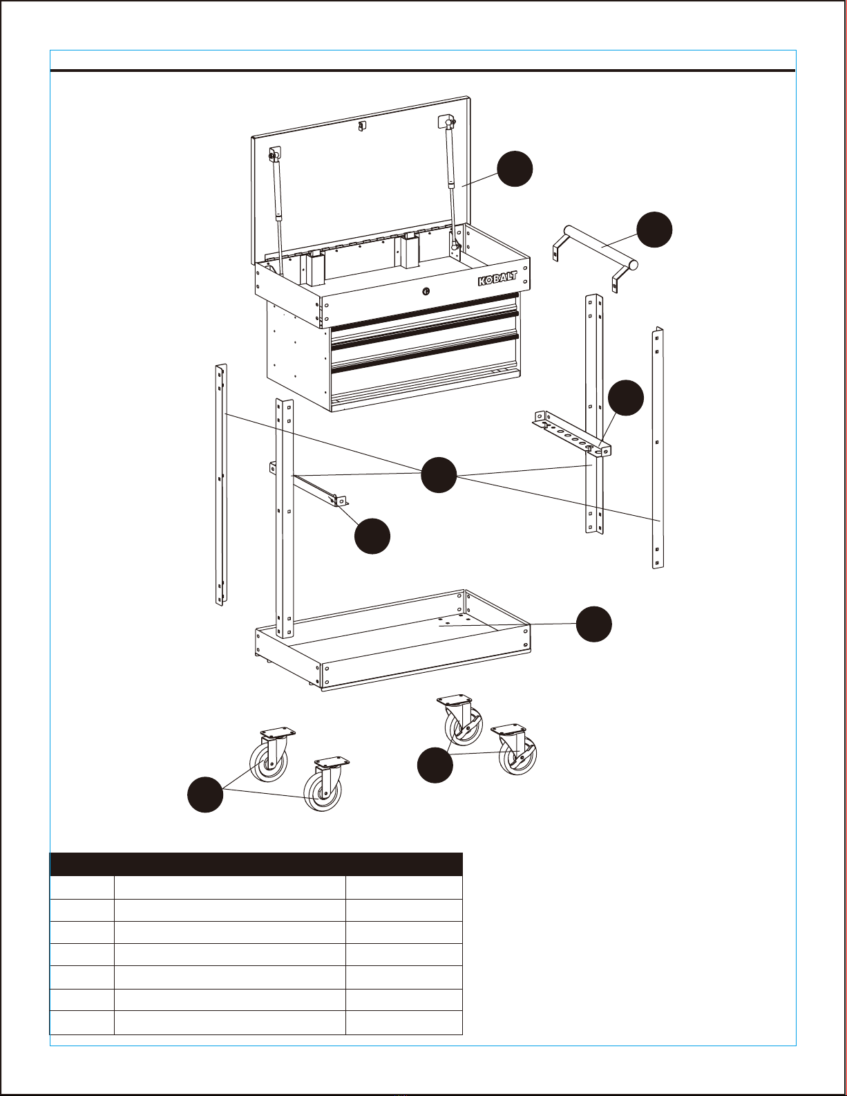
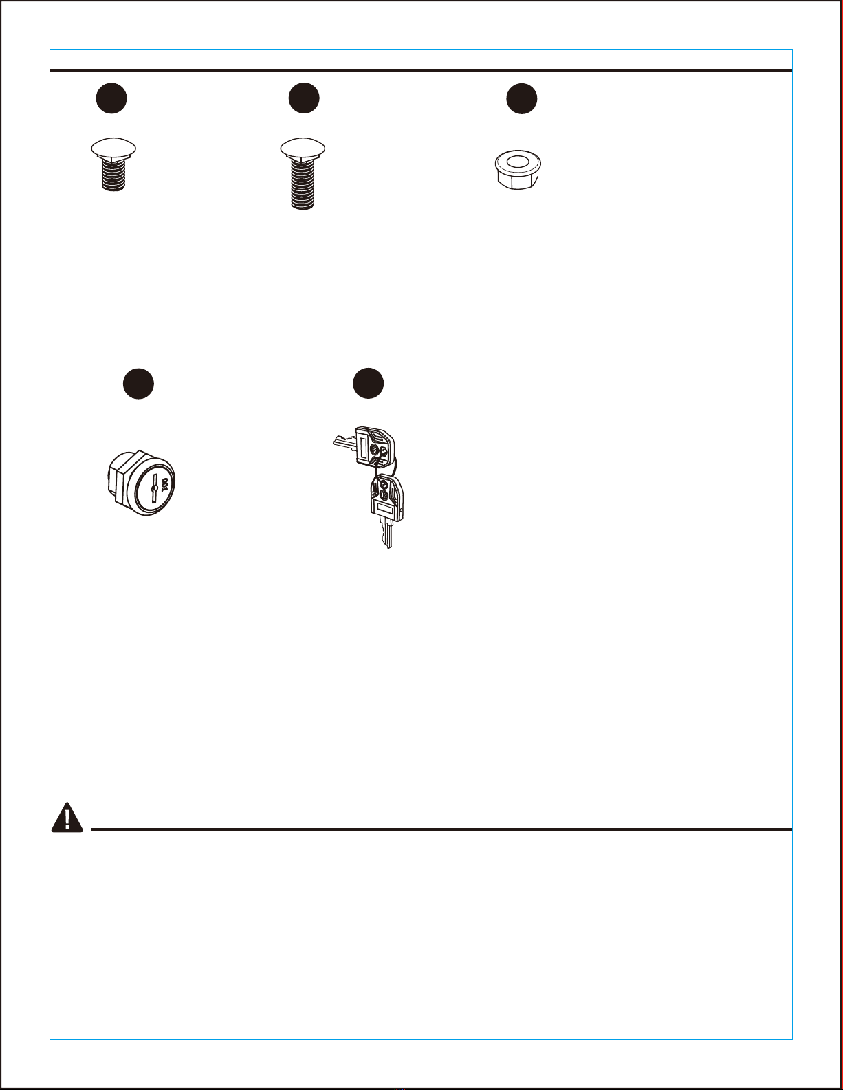
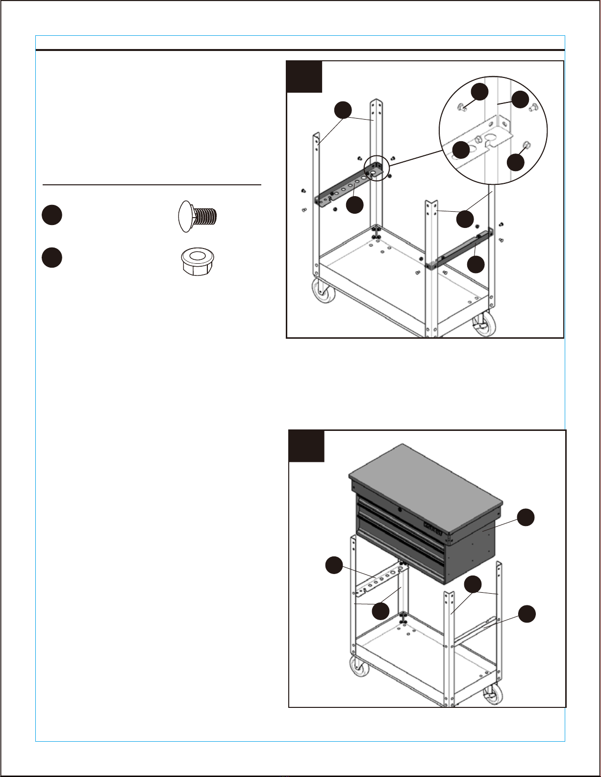
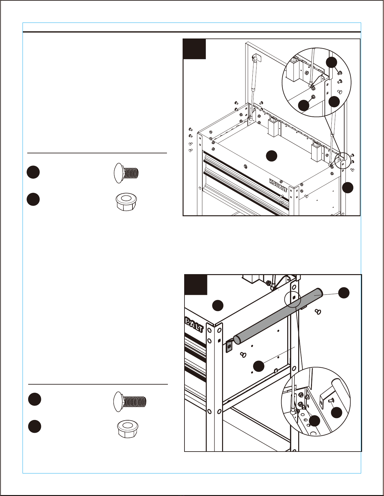
Before beginning assembly of product, make sure all parts are present. Compare parts with package
contents list and hardware contents above. If any part is missing or damaged, do not attempt to
assemble the product. Contact customer service for replacement parts.
It is recommended that this product to be assembled on a clean, soft surface, such as a piece of
cardboard.
Estimated Assembly Time: 45 minutes (does not include unpacking time)
Tools Required for Assembly (included): 13 mm Wrench
PREPARATION

ASSEMBLY INSTRUCTIONS
6
Hardware Used
BB x 16
M8 x 15 mm Bolt
CC x 16
M8 Nut
AA x 16
M8 x 11 mm Bolt
CC x 16
M8 Nut
1. Mount the two swivel casters with brake
(F) to the bottom of the bottom tray (E)
using four M8 x 15 mm bolts (BB) and M8
nuts (CC) per caster. The swivel casters
with brake (F) should be installed on the
same end as the side handle (B). Repeat
this process for the other swivel casters
(G) on the opposite end of the bottom tray
(E).Tighten all bolts with a 13 mm wrench.
Return the unit to its upright position.
Note: Do not over tighten the bolts.
Be sure to keep the tray on a soft surface,
such as carpeting or a piece of cardboard,
to protect them from scratches.
Hardware Used
2. Mount the four posts (C) to the bottom
tray (E) using four M8 x 11 mm bolts (AA)
and M8 nuts (CC) per post (C). Finger
tighten only.
Note: Lock 2 swivel casters to prevent it from
rolling and swiveling.
Be sure to install the posts in the direction
indicated by the arrow on the label, or the
next step will not be able to install.
Do not fully tighten bolts yet to allow for some
movement during cabinet installation.
1
2
E
G
F
C
C
E
BB
CC
CC
AA C

ASSEMBLY INSTRUCTIONS
7
Hardware Used
3. Mount the two beams (D) to four posts
(C) using eight M8 x 11 mm bolts (AA)
and M8 nuts (CC). Tighten the 8 bolts
securely.
4. Carefully and slowly lower the cabinet (A)
between the four posts (C) until the
cabinet (A) is properly secured onto the 2
beams (D) and the holes are in alignment.
Note: Lock the lid and all drawers before
operation.
This step requires at least two adults.
3
AA x 8
M8 x 11 mm Bolt
CC x 8
M8 Nut
C
C
D
D
A
D
C
C
D
4
CC
AA C
D

Hardware Used
BB x 2
M8 x 15 mm Bolt
CC x 2
M8 Nut
ASSEMBLY INSTRUCTIONS
8
Hardware Used
5. Unlock and open the lid, secure the
cabinet (A) to the four posts (C) using
fourteen M8 x 11 mm bolts (AA) and M8
nuts (CC). Do not over tighten the bolts.
6. Attach the side handle (B) to the tool cart
using two M8 x 15 mm bolts (BB) and M8
nuts (CC). Tighten all bolts securely.
Note: The side handle (B) must be installed
on the end of the tool cart with swivel casters
with brake (F).
Note: Do not install the top 2 bolts and nuts
on the side with the 2 swivel casters with
brake (F), they are for the side handle (B) in
next step. For easier assembling, screw the 2
bolts on the bottom side first.
5
AA x 14
M8 x 11 mm Bolt
CC x 14
M8 Nut
B
A
6
C
A
AA
C
C
CC
CC
BB

9
OPERATING INSTRUCTIONS
1. Using the caster brakes
To lock the swivel casters, step
down the levers marked with
ON. To unlock casters, push
down the levers marked with
OFF.
Note: Be sure to lock both swivel casters
with brake to prevent tool cart from rolling
or swiveling.
Note: Do not slide in the drawer violently
until both drawer slides are aligned
properly or it will cause damage on
drawer slide.
2. Removing the drawers
Fully empty and extend the drawer.
Depending on the side, either lift or
lower the release lever on both sides
so the slides can ride over the stops.
Pull the drawer outward until it is
released from the slides.
3. Re-inserting the drawers
Pull the slides and slide carrier out
until fully extended. Hold the slide on
the tool cart while aligning it with the
slide on the drawer. Slightly insert
one side and repeat for the other
side. Slowly push the drawer until it is
fully closed to engage the slide.
Open and close the drawer to verify
proper operation.
1
2
3
OFF
ON

10
CARE AND MAINTENANCE
3-YEAR HASSLE-FREE WARRANTY
• Keep your tool cart in good repair by adopting a regular maintenance program.
• The use of drawer liners (included) is recommended to protect the finish inside the drawers and
make the drawers easier to clean.
• Grease the casters annually using high quality bearing grease.
• Lubricate the slides semi-annually with general purpose grease or equivalent.
• Periodically clean the drawer fronts, drawer trim, and other surfaces with a mild detergent and
water.
• Remove grease and oil with a standard nonflammable cleaning fluid.
For 3 years from the date of purchase, this product is warranted for the original purchaser to
be free from defects in material and workmanship. This guarantee does not cover damage
due to abuse, normal wear, improper maintenance, neglect, unauthorized repair/alteration, or
expendable parts and accessories expected to become unusable after a reasonable period
of use.
If you think your product meets the above guarantee criteria, please call 1-888-3KOBALT, 8
a.m. – 8 p.m., EST, Monday – Sunday, or return the item to the place of purchase with a copy
of the original sales receipt. The distributor will, at its option, repair or replace the product.
This warranty gives you specific legal rights, and you may also have other rights that vary
from state to state.

11
REPLACEMENT PARTS LIST
For replacement parts, call our customer service department at 1-888-3KOBALT,
8 a.m. - 8 p.m., EST, Monday – Sunday.
Printed in China
A
B
C
D
E
F
G
H
3832633-A
3832633-B
3832633-C
3832633-D
3832633-E
3832633-F
3832633-G
3832633-H
Top lid
Side handle
Post
Beam
Bottom tray
Swivel caster with brake
Swivel caster
Gas strut
DESCRIPTION PART #PART
I
J
K
AA
BB
CC
DD
EE
3832633-TL
3832633-DL
3832633-DS
3832633-HDWR
3832633-HDWR
3832633-HDWR
3832633-LK
3832633-LK
Top tray liner
Drawer liner
Drawer slide
M8 x 11 mm Bolt
M8 x 15 mm Bolt
M8 Nut
Lock
Key
DESCRIPTION PART #PART
AA BB CC
DD EE
A
B
I
C
D
D
H
E
GF
J
K

12
Número de serie Fecha de compra
ADJUNTE SU RECIBO AQUÍ
Artículo #3832633
MODELO #59725
CARRITO DE
HERRAMIENTAS DE USO
GENERAL CON 3 GAVETAS
DE 77,47 CM
KOBALT y el diseño del logotipo son marcas comerciales o
marcas registradas de LF, LLC. Todos los derechos reservados.
¿Preguntas, problemas, piezas faltantes? Antes de volver a la tienda, llame a nuestro
Departamento de Servicio al Cliente al 1888-3KOBALT (1-888-356-2258), de lunes a
domingo de 8 a.m. a 8 p.m., hora estándar del Este. También puede ponerse en contacto
AS21264

13
ESPECIFICACIONES DEL PRODUCTO
ÍNDICE
COMPONENTES ESPECIFICACIONES
Carga máxima para la gaveta pequeña
Carga máxima para la gaveta mediana
Carga máxima para la gaveta grande
Carga máxima para la bandeja inferior
Carga máxima para la bandeja superior
Carga total máxima
22,68 kg
22,68 kg
45,35 kg
45,35 kg
45,35 kg
181,43 kg
Contenido del paquete..................................................................................................................14
Aditamentos.........................................................................................................................15
Información de seguridad...............................................................................................................15
Preparación ...................................................................................................................................16
Instrucciones de ensamblaje..........................................................................................................17
Instrucciones de funcionamiento....................................................................................................20
Cuidado y mantenimiento..............................................................................................................21
Garantía........................................................................................................................................21
Lista de piezas de repuesto...........................................................................................................22

CONTENIDO DEL PAQUETE
14
A
B
C
D
D
A
B
C
D
E
F
G
1
1
4
2
1
2
2
Gabinete
Mango lateral
Poste
Viga
Bandeja inferior
Rueda giratoria con freno
Rueda giratoria
PIEZA DESCRIPCIÓN CANTIDAD
E
G
F

INFORMACIÓN DE SEGURIDAD
Lea y comprenda completamente este manual antes de intentar ensamblar u operar este producto.
No seguirlo podría provocar lesiones serias. Guarde todas las advertencias e instrucciones para
referencia futura.
ADITAMENTOS (se muestran en tamaño real)
15
M8 x 11 mm
Perno
Cant. 38+3
Tuerca M8
Cant. 56+5
M8 x 15 mm
Perno
Cant. 18+2
AA BB CC
DD EE
Cerradura
(Preensamblado en
el gabinete)
Cant. 1
Llave
(Preensamblado en el
mecanismo de bloqueo)
Cant. 2

INFORMACIÓN DE SEGURIDAD
16
• No se pare, pise ni modifique esta unidad para ningún uso que no sea la función de almacenamiento
para la que se diseñó.
• Al bloquear el producto, cierre todas las gavetas y la cubierta superior por completo para que las
barras de bloqueo funcionen correctamente.
• Asegure todos los artículos y bloquee la tapa y todas las gavetas antes de hacer rodar este producto.
Solo haga rodar el producto distancias cortas utilizando el mango provisto.
• Bloquee las ruedas cuando no desee mover el producto.
• No abra más de una gaveta al mismo tiempo, ya que el producto puede ser inestable y volcarse, lo que
puede causar lesiones personales o daños al producto.
• El metal puede tener bordes o esquinas afiladas. Se recomienda el uso de guantes de protección.
• Siempre recuerde usar técnicas adecuadas de levantamiento cuando mueva la unidad ya sea en su
caja o una vez ensamblada.
• No fije o monte este producto sobre a un vehículo ni a ningún objeto que se desplace. Esto podría
causar lesiones personales o daños al producto.
• No exceda las capacidades de carga máximas que se indican en las Especificaciones del producto en
la página 2, incluido el contenido.
• Al almacenar artículos, distribuya las cargas por igual. Siempre equilibre las cargas para evitar vuelcos.
Coloque el peso mayor en la parte inferior del carrito cuando sea posible.
• Mantenga el producto en superficies niveladas. El producto puede volverse inestable y volcarse si se
almacena o desplaza sobre una superficie desnivelada, lo que puede causar lesiones personales o
daños al producto.
• No almacene líquidos inflamables en la unidad a menos que estén aseguradas en un envase aprobado.
• No almacene gasolina en la unidad bajo ninguna circunstancia.
• No deje a los niños sin supervisión cerca de este producto. El gabinete puede volcarse si se abre
incorrectamente.
• Siempre use el sentido común y tenga cuidado al usar este producto.
PRECAUCIÓN
ADVERTENCIA
Antes de comenzar a ensamblar el producto, asegúrese de tener todas las piezas. Compare las
piezas con la lista del contenido del paquete y la lista de aditamentos anteriores. No intente
ensamblar el producto si falta alguna pieza o si estas están dañadas. Póngase en contacto con el
Departamento de Servicio al Cliente para obtener piezas de repuesto.
Se recomienda que este producto se ensamble sobre una superficie limpia y suave, como un trozo
de cartón.
Tiempo estimado de ensamblaje: 45 minutos (no incluye el tiempo de desembalaje)
Herramientas necesarias para el ensamblaje (se incluyen): llave de 13 mm
PREPARACIÓN

INSTRUCCIONES DE ENSAMBLAJE
17
Aditamentos utilizados
BB x 16
Perno M8 x 15 mm
CC x 16
Tuerca M8
AA x 16
Perno M8 x 11 mm
CC x 16
Tuerca M8
1. Monte las dos ruedas giratorias con freno
(F) en la parte inferior de la bandeja
inferior (E) con cuatro pernos M8 x 15 mm
(BB) y tuercas M8 (CC) por rueda. Las
ruedas giratorias con freno (F) deben
instalarse en el mismo extremo que el
mango lateral (B). Repita este proceso con
las otras ruedas giratorias (G) en el
extremo opuesto de la bandeja inferior (E).
Apriete todos los pernos con una llave
inglesa de 13 mm. Vuelva a colocar la
unidad en posición vertical.
Nota: no apriete los pernos en exceso.
Asegúrese de mantener la bandeja sobre
una superficie suave, como una alfombra o
un trozo de cartón, para evitar rayarla.
Aditamentos utilizados
2. Monte los cuatro postes (C) en la bandeja
inferior (E) con cuatro pernos M8 x 11
mm (AA) y tuercas M8 (CC) por poste
(C). Apriete con los dedos solamente.
Nota: bloquee las 2 ruedas giratorias para
evitar que rueden y giren. Asegúrese de
instalar los postes en la dirección que indica
la flecha en la etiqueta, o en el siguiente paso
no podrá instalar. Aún no apriete
completamente los pernos para permitir el
movimiento durante la instalación del
gabinete.
1
2
E
G
F
C
C
E
BB
CC
CC
AA C

INSTRUCCIONES DE ENSAMBLAJE
18
Aditamentos utilizados
3. Monte las dos vigas (D) en cuatro
postes (C) con ocho pernos M8 x 11
mm (AA) y tuercas M8 (CC). Apriete
firmemente los 8 pernos.
4. Con cuidado y lentamente, baje el
gabinete (A) entre los cuatro postes (C)
hasta que el gabinete (A) quede
correctamente asegurado en las 2 vigas
(D) y los orificios estén alineados.
Nota: cierre la tapa y todas las gavetas antes
de la operación.
Se requieren al menos dos adultos para este
paso.
3
AA x 8
Perno M8 x 11 mm
CC x 8
Tuerca M8
C
C
D
D
A
D
C
C
D
4
CC
AA C
D

Aditamentos utilizados
BB x 2
Perno M8 x 15 mm
CC x 2
Tuerca M8
INSTRUCCIONES DE ENSAMBLAJE
19
Aditamentos utilizados
5. Desbloquee y abra la tapa, asegure el
gabinete (A) a los cuatro postes (C) con
catorce pernos M8 x 11 mm (AA) y
tuercas M8 (CC). No apriete los pernos
en exceso.
6. Fije el mango lateral (B) al carrito de
herramientas con dos pernos M8 x 15
mm (BB) y tuercas M8 (CC). Apriete
firmemente todos los pernos.
Nota: el mango lateral (B) debe instalarse en
el extremo del carrito para herramientas con
las ruedas giratorias con freno (F).
Nota: no instale los 2 pernos y tuercas
superiores en el lado con las 2 ruedas
giratorias con freno (F), ya que son para el
mango lateral (B) en el siguiente paso. Para
facilitar el montaje, atornille primero los 2
pernos del lado inferior.
5
AA x 14
Perno M8 x 11 mm
CC x 14
Tuerca M8
B
A
6
C
A
AA
C
C
CC
CC
BB

20
INSTRUCCIONES DE FUNCIONAMIENTO
1. Uso de los frenos de las ruedas
Para bloquear las ruedas giratorias,
baje las palancas marcadas con ON
(activado). Para desbloquear las
ruedas giratorias, presione hacia
abajo las palancas marcadas con OFF
(desactivado).
Nota: asegúrese de bloquear las ruedas
giratorias con freno para evitar que el
carrito de herramientas se mueva o gire.
Nota: no deslice violentamente la gaveta
hasta que ambos deslizadores de gaveta
estén alineados correctamente o se dañará
el deslizador para gaveta.
2. Retiro de las gavetas
Vacíe por completo y extienda la
gaveta Según el lado, levante o baje la
palanca de liberación en ambos lados
para que los deslizadores pasen sobre
los topes. Tire de la gaveta hacia
afuera hasta que se libere de los
deslizadores.
3. Reinserción de las gavetas
Tire de los deslizadores y deslice el
soporte hacia afuera hasta que esté
completamente extendido. Sostenga el
deslizador en el carrito para herramientas
mientras que lo alinea con el deslizador
en la gaveta. Introduzca ligeramente un
lado y repita para el otro lado. Empuje
lentamente la gaveta hasta que esté
completamente cerrada para enganchar
el deslizador. Abra y cierre la gaveta para
verificar el funcionamiento correcto.
1
2
3
OFF
ON
This manual suits for next models
1
Table of contents
Languages:
Other Kobalt Outdoor Cart manuals