Kobold TIN-SS User manual

Operating Instructions
for
Infrared Pyrometer
Model: TIN-SS

TIN-SS
page 2 TIN-SS K01/1023
We don’t accept warranty and liability claims neither upon this publication nor in
case of improper treatment of the described products.
The document may contain technical inaccuracies and typographical errors. The
content will be revised on a regular basis. These changes will be implemented in
later versions. The described products can be improved and changed at any time
without prior notice.
© Copyright
All rights reserved.
1. Contents
1.Contents ........................................................................................................ 2
2.Note .............................................................................................................. 4
3.Instrument Inspection .................................................................................... 4
4.Regulation Use ............................................................................................. 5
5.Operating Principle ........................................................................................ 6
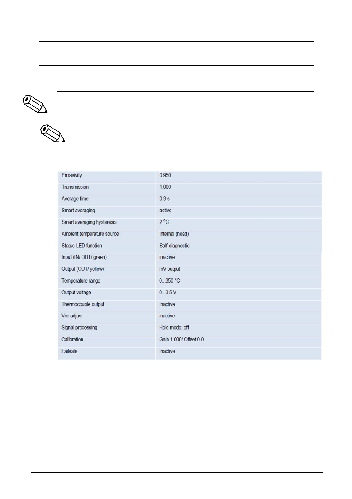
5.1Default settings .................................................................................... 6
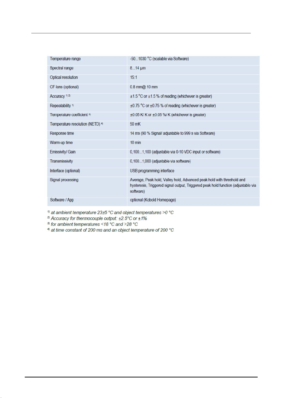
5.2General specifications.......................................................................... 8
5.3Electrical specifications ........................................................................ 8
5.4 Measurement specifications ............................................................. 10
5.5Optical charts ..................................................................................... 11
5.6 Close focus optics ............................................................................. 11
5.7LED-Functions ................................................................................... 12
6.Installation ................................................................................................... 14
6.1Mechanical Installation ...................................................................... 14
7.Electrical Installation ................................................................................... 17
7.1Digital communication ........................................................................ 18
7.2Open collector output ......................................................................... 18
8.Schematic circuit diagrams for maintenance applications ........................... 19
9.Software for parameterization ..................................................................... 20
9.1Installation .......................................................................................... 20
9.2Communication settings ..................................................................... 21
10.Basics of Infrared Thermometry .................................................................. 21
11.Emissivity .................................................................................................... 22
11.1Definition ............................................................................................ 22
11.2Determination of unknown emissivity ................................................. 22
11.3Characteristic emissivity .................................................................... 23
12.Maintenance ............................................................................................... 23
13.Technical Information .................................................................................. 24
14.Order Codes ............................................................................................... 24
15.Dimensions ................................................................................................. 24
16.Disposal ...................................................................................................... 25
17.EU Declaration of Conformance ................................................................. 26
18.Appendix A – Table of emissivity for metals ................................................ 27

TIN-SS
TIN-SS K01/1023 page 3
19.Appendix B - Table of emissivity for non-metals ......................................... 27
20.Appendix D – Smart Averaging ................................................................... 28
Manufactured and sold by:
Kobold Messring GmbH
Nordring 22-24
D-65719 Hofheim
Tel.: +49(0)6192-2990
Fax: +49(0)6192-23398
E-Mail: [email protected]
Internet: www.kobold.com

TIN-SS
page 4 TIN-SS K01/1023
2. Note
Please read these operating instructions before unpacking and putting the unit
into operation. Follow the instructions precisely as described herein.
The instruction manuals on our website www.kobold.com are always for currently
manufactured version of our products. Due to technical changes, the instruction
manuals available online may not always correspond to the product version you
have purchased. If you need an instruction manual that corresponds to the
purchased product version, you can request it from us free of charge by email
([email protected]) in PDF format, specifying the relevant invoice number and
serial number. If you wish, the operating instructions can also be sent to you by
post in paper form against an applicable postage fee.
Operating instructions, data sheet, approvals and further information via the QR
code on the device or via www.kobold.com
The devices are only to be used, maintained and serviced by persons familiar
with these operating instructions and in accordance with local regulations
applying to Health & Safety and prevention of accidents.
When used in machines, the measuring unit should be used only when the
machines fulfil the EC machinery directive.
3. Instrument Inspection
Instruments are inspected before shipping and sent out in perfect condition.
Should damage to a device be visible, we recommend a thorough inspection of
the delivery packaging. In case of damage, please inform your parcel service /
forwarding agent immediately, since they are responsible for damages during
transit.
Scope of delivery:
The standard delivery includes:
Infrared Pyrometer model: TIN-SS

TIN-SS
TIN-SS K01/1023 page 5
4. Regulation Use
Any use of the device, which exceeds the manufacturer’s specification, may
invalidate its warranty. Therefore, any resulting damage is not the responsibility of
the manufacturer. The user assumes all risk for such usage.
The sensors of the TIN-SS series are non-contact infrared temperature sensors.
They calculate the surface temperature based on the emitted infrared energy of
objects (see chapter 10 Basics of Infrared Thermometry).
The TIN-SS sensing head is a sensitive optical system. Please use only the
thread for mechanical installation.
Avoid abrupt changes of the ambient temperature.
Avoid mechanical violence on the head – this may destroy the system
(expiry of warranty).
If you have any problems or questions, please contact our service
department.

TIN-SS
page 6 TIN-SS K01/1023
5. Operating Principle
5.1 Default settings
Smart Averaging means a dynamic average adaptation at high signal
edges. [Activation via software only]. [see Appendix D – Smart Averaging]
The default settings can be changed with the optional USB adapter
cable & software. If the unit is supplied together with the IR App
Connector cable the output is already preset to digital communication
(bidirectional).
At time of delivery the unit has the following pre-settings:

TIN-SS
TIN-SS K01/1023 page 7
For a usage of the TIN-SS for online maintenance applications (in electrical
cabinets e.g.) the following recommend settings are already included in the
factory default setting (but not active):

TIN-SS
page 8 TIN-SS K01/1023
5.2 General specifications
5.3 Electrical specifications

TIN-SS
TIN-SS K01/1023 page 9

TIN-SS
page 10 TIN-SS K01/1023
5.4 Measurement specifications

TIN-SS
TIN-SS K01/1023 page 11
5.5 Optical charts
●
The size of the measuring object and the optical resolution of the
infrared thermometer determine the maximum distance between sensing
head and measuring object.
● In order to prevent measuring errors the object should fill out the field
of view of the optics completely. Consequently, the spot should at all
times have at least the same size like the object or should be smaller
than that.
The following optical charts show the diameter of the measuring spot in
dependence on the distance between measuring object and sensing head. The
spot size refers to 90 % of the radiation energy.
The distance is always measured from the front edge of the sensor housing/ CF-
lens holder/ air purge.
Optical chart TIN-SS (15:1)
Optical chart TIN-SS (15:1) with CF-lens (0.8 mm@ 10 mm)
5.6 Close focus optics
● If the CF-lens is used, the transmission has to be set to 0.78. To
change this value the optional USB-Kit (including software) is
necessary.
● The assigned transmission (average value) is a characteristic value
which may has a certain scattering. If required the transmission has to
be determined.

TIN-SS
page 12 TIN-SS K01/1023
The optional CF-lens allows the measurement of small objects. The CF optics
can also be combined with a laminar air purge
CF-lens [Order-No.: TIN-ZTCF]
5.7 LED-Functions
The green LED can be programmed for the following functions. For the
programming the USB adapter cable incl. software (option) is necessary. The
factory default setting for the LED is self-diagnostic.
5.7.1 Automatic aiming support
The automatic aiming support helps to adjust the unit to an object which has a
temperature different to the background. If this function is activated via software
the sensor is looking for the highest object temperature; means the threshold
value for activating the LED will be automatically tuned.
This works also if the sensor is aimed at a new object (with probably colder
temperature). After expiration of a certain reset time (default setting: 10 s) the
sensor will adjust the threshold level for activation of the LED new.
5.7.2 Self-diagnostic
At a supply voltage (Vcc) ≥ 12 V it takes about 5 minutes until the sensor
works in a stable mode. Therefore, after switching on the unit, the LED will
show a not stable state for up to 5 minutes.

TIN-SS
TIN-SS K01/1023 page 13
With this function the current status of the sensor will be indicated by different
flash modes of the LED.
Sensor status
5.7.3 Temperature code indication
With this function the current measured object temperature will be indicated as
percentage value by long and short flashing of the LED. At a range setting of 0-
100 °C → 0-100 % the LED flashing indicates the temperature in °C.
Examples
87 °C 8-times long flashing indicates 87
and afterwards 7-times short flashing indicates 87
31 °C 3-times long flashing indicates 31
and afterwards 1-times short flashing indicates 31
8 °C 10-times long flashing indicates 08
and afterwards 8-times short flashing indicates 08
20 °C 2-times long flashing indicates 20
and afterwards 10-times short flashing indicates 20

TIN-SS
page 14 TIN-SS K01/1023
6. Installation
6.1 Mechanical Installation
The TIN-SS is equipped with a metric M12x1 thread and can be installed either
directly via the sensor thread or with the help of the both hex nuts (standard) to
the mounting bracket available.
Dimensions TIN-SS
For an exact aiming of the sensor to an object the LED function, see chapter
5.7.1 Automatic aiming support, can be used.
6.1.1 Mounting accessories
Mounting bracket, adjustable in one axis
[Order-No.: TIN-ZTFB]
Mounting bracket, adjustable in
one axis, probe and laser
sighting aid
[Order No.: TIN-ZTF2]

TIN-SS
TIN-SS K01/1023 page 15
Mounting fork with M12x1 thread, Mounting bracket, adjustable in
Adjustable in two axes two axes
see air purge collar [Order-No.: TIN-ZTAB]
battery
powered

TIN-SS
page 16 TIN-SS K01/1023
6.1.2 Air purge collar
● Use oil-free, technically clean air only.
● The needed amount of air (approx. 2...10 l/ min.) depends on the
application and the installation conditions on-site.
The lens must be kept clean at all times from dust, smoke, fumes and other
contaminants in order to avoid reading errors. These effects can be reduced by
using an air purge collar.
Free blowing offset, laminar, with mounting fork, adjustable in two axes,
model TIN-ZTAP
A combination of the laminar air purge collar with the bottom section of the
mounting fork allows an adjustment in two axes.
[Order-No.: TIN-ZTAP]
IR App Connector: USB adapter cable incl. terminal block
[Order-No.: TIN-ZSIA]

TIN-SS
TIN-SS K01/1023 page 17
7. Electrical Installation
Use a separate, stabilized power supply unit with an output voltage in the
range of 5–30 VDC which can supply 100 mA. The residual ripple should be
max 200 mV.
Note: The TIN-SS sensor may only be powered either via USB or externally,
but not simultaneously!
Use shielded cables only. The sensor shield has to be grounded.
The shield [black] on the TIN-SS is not connected to GND [brown].In any
case it is necessary to connect the shield to ground or GND (whichever
works best)!
When using the thermocouple and an external power supply, there must
be a connection between ground and shield.
Analog device (mV-output at OUT pin)
The output impedance must be ≥ 10 kΩ.
Analog device (mV output at OUT pin)
Analog device (Thermocouple typ K at OUT t/c K pins)
The output impedance must be ≥ 20 kΩ.
Analog device (Thermocouple typ K at OUT t/c K pins)
You can choose between an mV output (0-5 or 0-10 V; scalable via software) and
a thermocouple output type K. Therefor the optional software is needed. The
factory default setting is mV output.

TIN-SS
page 18 TIN-SS K01/1023
The thermocouple output supplies a voltage according to the t/c characteristic
curve type K. If you want to extend this output you have to use a suitable
thermocouple extension cable (NiCr-Ni).
7.1 Digital communication
For a digital communication the optional USB programming kit is required.
1. Connect each wire of the USB adapter cable with the same colored wire of
the sensor cable by using the terminal block. Press with a screw driver as
shown in the picture to lose a contact.
Connection USB cable
The sensor is offering two ways of digital communication:
bidirectional communication (sending and receiving data)
unidirectional communication (burst mode – the sensor is sending data only)
Digital communication
7.2 Open collector output
In case of long lines there is a drop voltage at the ground wire and the mV-
output is distorted. Because of that the brown wire can be used as ground
supply and the t/c- wire (type K) as measuring ground.

TIN-SS
TIN-SS K01/1023 page 19
Open collector output as additional alarm output
The open collector output is an additional alarm output on the TIN-SS and can
control an external relay e.g. In addition, the analogue output can be used
simultaneously.
8. Schematic circuit diagrams for maintenance
applications
Open collector output for direct 24 V DC signal lamp control

TIN-SS
page 20 TIN-SS K01/1023
9. Software for parameterization
Minimum system requirements:
Windows 7, Windows 8, Windows 10
USB interface
Hard disc with at least 30 MByte of free space
At least 128 MByte RAM
The software only supports USB cables ordered directly from Kobold Messring,
see USB-interface TIN-ZSIA
9.1 Installation
You can download the software for parameterization and data recording for
Windows
®
from the Kobold homepage.
www.kobold.com/qr/TIN
Please follow the instructions after starting the setup file.
For communication between the sensor and PC, install the drivers for the USB
adapter.
If you want to uninstall the software from your system, please use the uninstall
function.
Software for Windows
Main functions:
Graphic display for temperature trends and automatic data logging for
analysis and documentation
Complete sensor setup and remote controlling
Adjustment of signal processing functions
Programming of outputs and functional inputs
Table of contents
Other Kobold Measuring Instrument manuals

Kobold
Kobold VKM User manual

Kobold
Kobold DPE Series User manual

Kobold
Kobold KAL-A User manual

Kobold
Kobold DVZ User manual

Kobold
Kobold Heinrichs V31 User manual

Kobold
Kobold HND-P105 User manual

Kobold
Kobold NMT User manual

Kobold
Kobold DUC-MF1 User manual

Kobold
Kobold OPT-Y24896/0001 User manual

Kobold
Kobold DIG Series User manual

Kobold
Kobold LFM User manual

Kobold
Kobold DON-05Lx User manual

Kobold
Kobold DRH Series User manual

Kobold
Kobold UTS User manual

Kobold
Kobold DAG-A44 Series User manual

Kobold
Kobold OMS User manual

Kobold
Kobold APS-Z User manual

Kobold
Kobold KEC-2 User manual

Kobold
Kobold DPT Series User manual

Kobold
Kobold MIK Series User manual