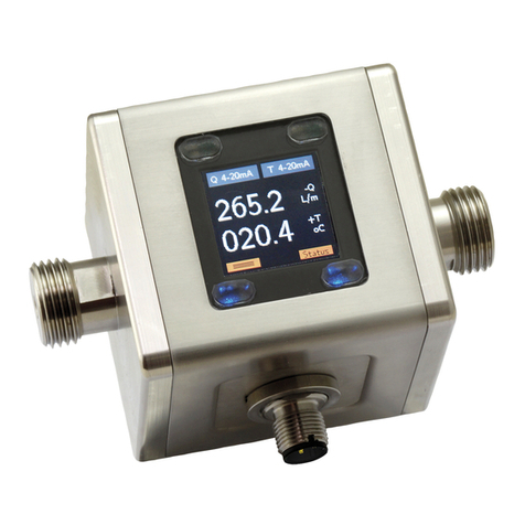
Kobold DVZ User manual

Operating Instructions
for
Compact Vortex Flow Meter
Model: DVZ

DVZ
page 2 DVZ K13/0423
1. Contents
1.Contents ........................................................................................................ 2
2.Note .............................................................................................................. 3
3.Instrument Inspection .................................................................................... 3
4.Regulation Use ............................................................................................. 4
5.Operating Principle ........................................................................................ 4
6.Mechanical Connection ................................................................................. 5
6.1Check operating conditions: ................................................................. 5
6.2Installation ............................................................................................ 5
7.Electrical Connection .................................................................................... 6
7.1General ................................................................................................ 6
7.2DVZ-...S300 ......................................................................................... 6
7.3DVZ-...S30D ........................................................................................ 6
7.4DVZ-...F300; DVZ-...L3x3 .................................................................... 7
7.5DVZ-...L443 ......................................................................................... 7
7.6DVZ-...C30 ........................................................................................... 7
7.7DVZ-...C34 ........................................................................................... 8
7.8DVZ-...Ex4R, DVZ-...Gx4R .................................................................. 9
8.Operation .................................................................................................... 10
8.1Switch point setting DVZ-...S300, DVZ-…S30D ................................ 10
8.2Counter electronics DVZ-…Ex4R ...................................................... 10
8.3Dosing electronics DVZ-…Gx4R ....................................................... 10
9.Adjustments – Compact Electronic DVZ-...C3............................................. 11
9.1Button function ................................................................................... 11
9.2Settings .............................................................................................. 11
9.3Value setting ...................................................................................... 12
9.4Set-up mode ...................................................................................... 13
9.5Main menu items ............................................................................... 15
10.Maintenance ............................................................................................... 18
11.Technical Information .................................................................................. 18
12.Order Codes ............................................................................................... 18
13.Dimensions ................................................................................................. 18
14.Disposal ...................................................................................................... 19
15.EU Declaration of Conformity ...................................................................... 20
16.UK Declaration of Conformity ...................................................................... 21
Manufactured and sold by:
Kobold Messring GmbH
Nordring 22-24
D-65719 Hofheim
Tel.: +49(0)6192-2990
Fax: +49(0)6192-23398
E-Mail: [email protected]
Internet: www.kobold.com

DVZ
DVZ K13/0423 page 3
2. Note
Please read these operating instructions before unpacking and putting the unit
into operation. Follow the instructions precisely as described herein.
The instruction manuals on our website www.kobold.com are always for currently
manufactured version of our products. Due to technical changes, the instruction
manuals available online may not always correspond to the product version you
have purchased. If you need an instruction manual that corresponds to the
purchased product version, you can request it from us free of charge by email
([email protected]) in PDF format, specifying the relevant invoice number and
serial number. If you wish, the operating instructions can also be sent to you by
post in paper form against an applicable postage fee.
Operating instructions, data sheet, approvals and further information via the QR
code on the device or via www.kobold.com
The devices are only to be used, maintained and serviced by persons familiar
with these operating instructions and in accordance with local regulations
applying to Health & Safety and prevention of accidents.
When used in machines, the measuring unit should be used only when the
machines fulfil the EC-machine guidelines.
as per PED 2014/68/EU
In acc. with Article 4, Paragraph (3), "Sound Engineering Practice", of the
PED 2014/68/EU no CE mark.
Diagram 8, Pipelines, Group 1, dangerous fluids
3. Instrument Inspection
Instruments are inspected before shipping and sent out in perfect condition.
Should damage to a device be visible, we recommend a thorough inspection of
the delivery packaging. In case of damage, please inform your parcel service /
forwarding agent immediately, since they are responsible for damages during
transit.
Scope of delivery:
The standard delivery includes:
Compact Vortex Flow Meter model: DVZ

DVZ
page 4 DVZ K13/0423
4. Regulation Use
Any use of the Compact Vortex flow meter, model: DVZ, which exceeds the
manufacturer’s specifications, may invalidate its warranty. Therefore, any
resulting damage is not the responsibility of the manufacturer. The user assumes
all risk for such usage.
5. Operating Principle
The compact KOBOLD Vortex flow meter, model DVZ, is used for measuring and
monitoring smaller and medium-sized flow of low viscosity, water-like fluids in
pipes.
The device works using the vortex process, making it virtually maintenance-free.
This involves the installation of a sharp-edged object (the vortex generator) in the
flow duct. A vortex is created behind the object whose frequency is proportional
to the flow velocity of the fluid.
The flow volume can be determined with a very great degree of accuracy by
measuring the vortex frequency. This achieves a very high linearity across the
whole measuring range.
The device can be fitted with switching, frequency or analogue outputs. There is
also an optional compact electronics package that includes a digital display, and
both a switching and analogue output.

DVZ
DVZ K13/0423 page 5
6. Mechanical Connection
6.1 Check operating conditions:
Flow rate
max. operating pressure
max. operating temperature
6.2 Installation
Remove all packing materials and transport retainers and ensure that no such
materials remain in the device.
Install with flow in direction of arrow
(universal mounting)
Avoid pressure and radial tension
Fasten the pipe at up stream and down
stream at a distance of 50 mm from the
connections
Attention! Retransfer the unit on
the metal bolting (not on the
plastic housing!) Mount switches
using the proper tightening
torque according the following
table!
Nominal size of
threads
Proper tightening torque
3/8” 22 to 24 Nm
1/2” 28 to 30 Nm
3/4” 28 to 30 Nm
1” 36 to 38 Nm
Note! The switch may be damaged if it is tightened above the
tightening torque range. Also, if it is tightened below the tightening
torque range, the connecting thread section may loosen.
Ensure inlet section of 10xDN and outlet section of 10xDN
Avoid valves or large reduction on the inlet section (this increases the
inaccuracy of measurements)
Check the seals of the connections
Attention! When used with an open output side, there is a danger of
cavitation.

DVZ
page 6 DVZ K13/0423
7. Electrical Connection
7.1 General
Attention! Make sure that the voltage values of your system
correspond with the voltage values of the measuring unit.
Make sure that the supply wires are de-energised.
Connect the supply voltage and the output signal to the plug PIN’s as stated
below.
We recommend the use of wires with cross sectional area of min. 0,25 mm².
7.2 DVZ-...S300
7.3 DVZ-...S30D
1
2
34
Output
N/C
Output
N/O
+Vs
GND
1
2
34
5
Output
N/O
Output
Common
Output
N/C
+Vs
GND

DVZ
DVZ K13/0423 page 7
7.4 DVZ-...F300; DVZ-...L3x3
Connection example DVZ-...L3x3
1
2
34
+Vs
Signal
Out
n.c.
GND
7.5 DVZ-...L443
7.6 DVZ-...C30
1
2
34
5
Switch
Out 2
Switch
Out 1
+Vs
GND
GND
+Vs
Signal
Out
+Vs
GND
GND
1
2
34
+Vs
Signal
Out
n.c.
GND
+Vs
GND

DVZ
page 8 DVZ K13/0423
7.7 DVZ-...C34
1
2
34
5
+Vs
GND
GND
Switch out
1
0(4)-20 mA

DVZ
DVZ K13/0423 page 9
7.8 DVZ-...Ex4R, DVZ-...Gx4R
Cable connection
Wire number DVZ-...E14R
Counter electronics
DVZ-...G14R
Dosin
g
electronics
1 +24 VDC +24 VDC
2 GND GND
3 4-20 m
A
4-20 m
A
4 GND GND
5 n. c. control 2*
6 reset part quantit
y
control 1*
7 relay S1
normally open
relay S1
normally open
8
9 relay S2
normally open
relay S2
normally open
10
*Start-dosing: Control 1 connect with GND
Stop-dosing: Control 2 connect with GND
Reset-dosing: Control 1 and Control 2 at the same time with GND
Do not connect any external voltage to the control units!
Plug connection
-E34 R
+ Vs
Reset TM
0 (4) - 20 mA
GND
1
30 V / 2 A
AC/DC
34
5
1
3
4
5
6
S 2 8
d.c. *)
Output
d.c.*) Don't connect!

DVZ
page 10 DVZ K13/0423
8. Operation
The units are preset and after electrical connection ready for operation.
8.1 Switch point setting DVZ-...S300, DVZ-…S30D
Switch setting Switch point
0 switch function deactivated
1 start of measuring range
2 20% of f.s.
3 30% of f.s.
4 40% of f.s.
5 50% of f.s.
6 60% of f.s.
7 70% of f.s.
8 80% of f.s.
9 90% of f.s.
Flow above switch point: DUO-LED green
Flow below switch point: DUO-LED red
Measuring range overflow: DUO-LED orange flashing
8.2 Counter electronics DVZ-…Ex4R
Operating please see Operating Instructions ZED-Z
8.3 Dosing electronics DVZ-…Gx4R
Operating please see Operating Instructions ZED-D

DVZ
DVZ K13/0423 page 11
9. Adjustments – Compact Electronic DVZ-...C3..
Connect the compact electronic according to previous connection diagram. After
power on, the measuring range (end current) will be shown for 3 seconds.
9.1 Button function
In the normal mode (measuring mode)
In the set-up mode
9.2 Settings
The following values can be changed in the compact electronics:
Scale range Factory setting
Switch point (SPo, SP1, SP2) 0...999 0,00
Hysteresis (HYS) -199...0 -0,00
Window point (duo point) (duo) Switch point ...999 --- (inactive)
contact-type (Con, Co1, Co2) N/O, N/C or Frequency (Fr)** N/O
Start current (S-C)* 000...999 000
End current (E-C)* 000...999 f.s.
Start current selection (SCS) 0-- (0 mA), 4-- (4 mA) 4 mA
Change Code (CCo) 000...999 000
* Start- and end value of flow relating to 0/4-20 mA.
** not calibrated, frequency at f.s. approx. 500 -600Hz
:
Press 3 sec. Setup mode
:
Switch point/Window point
: Next Step
: Change Value 3 sec
Standard mode
Md
Any time
Id
or do not press
a button for 20 sec

DVZ
page 12 DVZ K13/0423
9.3 Value setting
From the main menu item (for example: switch point, "SPo"), press the ""
button to set the value. The flow chart below illustrates the universal routine for
changing individual parameters.
[From the main menu item]
1. Adjust position
2. Adjust position
3. Adjust position
Adjust decimal point
Save selected value
or
enter new value.
[To the next main menu
item]
save

DVZ
DVZ K13/0423 page 13
9.4 Set-up mode
Compact electronic DVZ-...C30..
Contact 2
function N/O
N/C Save
Code entering
Value setting
Contact 1
function
N/C
Frequency Save
Hysteresis
Value setting
Switching
point 2
Value setting
Switching
point 1 Value setting
Code=
3 sec
Code entering
Value setting

DVZ
page 14 DVZ K13/0423
Compact electronic DVZ-...C34
Contact
function N/O
N/C
Frequency Save
Code entering
Window point
Hysteresis
Switching point
3 sec
Code=
End current
Start current
7sec
7sec
Value setting
Value setting
Value setting
Value setting
Value setting
Value setting

DVZ
DVZ K13/0423 page 15
9.5 Main menu items
9.5.1 Switching point
The switching point is entered in the menu item "Spo, SP1, SP2". A setting value
between 000 and 999 can be selected. This value can also include a decimal
point. The decimal point can be set at two points (e.g. 10.0 or 1.00). If the display
value exceeds the set switch point, the electronic is activated and is signalised by
a lightning LED.
If the hysteresis is equal to zero and the window point is de-activated, the
electronic switches back whenever the indicated value falls below the switching
point.
9.5.2 Hysteresis
After the setting of the switching point, the hysteresis can be entered as a
negative value in the "HYS" menu. The standard hysteresis value is zero. In
operation condition this can lead to ambiguous switching behaviour, if the reading
fluctuates around the switching point or window point. In this case, increasing the
hysteresis can put things right. The hysteresis relates to the switching point and
the window point (switching point minus hysteresis; window point plus
hysteresis).
Example: Switching point 100 l/min; Hysteresis: -2.5 l/min
The electronic switches when 100 l/min is exceeded and switches
back when the reading drops below 97.5 l/min.
9.5.3 Window point (duo-point)
As well as the switching point, it is also to define a "duo" (duo-point), the window
point. This must be higher than the switching point. By using the window point
and the switching point it is possible to monitor the measurement value in a
certain range. The switching point limits the measurement range to smaller
values and the window point to larger values.
Changing code
Value setting
Storing
7sec
4-20
mA
0-20
mA
Analog output
choosing

DVZ
page 16 DVZ K13/0423
If the window point (duo-point) is less than or equal to the switching
point, an error report (Er4) will be indicated on the display and its
value is deleted and its function is invalid (in the case that the
window point and switching point out of adjustment).
The value is set in the same way as the switching point.
The window point is needed for process, in which monitoring of a certain
temperature range is necessary.
Example: Switching point: 100 L/min; window point: 150 L/min;
hysteresis: -1 L/min
The electronic switches when 100 l/min is exceeded. If the switching value
remains between 99 L/min (100-1) and 151 L/min (150+1), the contact will also
remain in active switching condition (LED on). If it exceeds 151 l/min or is below
99 l/min the electronic switches back.
Switching behaviour
The following diagram clarifies the switching behaviour of the electronic switch.
The contact closes (contact type: no) when it drops below the switching point or
the window point. It only opens again if the window point plus hysteresis is
exceeded or if it drops below the switching point minus hysteresis. An LED
indicates the switching condition of the switching point.
Time / t
Display
bar (°C)
Hysteresis
LED on
Time / t
Display
bar (°C)
Switchpoint
Hysteresis
LED on
Hysteresis
Window point
LED on
Flow
Flow

DVZ
DVZ K13/0423 page 17
9.5.4 Contact type
The function of the transistor switching output is set in menu item "Con, Co1 or
Co2". The switching function switches from
no - N/O contact to
nc - N/C to
Fr – frequency (only Con and Co1)
and back.
N/O contact: contact closes when switching point is exceeded
N/C contact: contact opens when switching point is exceeded
Frequency: frequency output synchronised with the vane frequency
9.5.5 Current output
The current output is selected in menu items
"S-C" Start current indicated value < > 0(4) mA
"E-C" End current indicated value < > 20 mA
"SCS" Start current selection (0-20 mA or 4-20 mA).
The indicated value at which 0(4) mA flow is entered in menu item Start current.
The indicated value at which 20 mA flow is entered in menu item End current.
9.5.6 Change Code
The change code option "CCo" secures the unit against unauthorised tampering.
If the code is different from 000, the user must input the code immediately after
entering the adjustment mode.

DVZ
page 18 DVZ K13/0423
10. Maintenance
The measurement device requires no maintenance if the measurement medium
does not cause deposits or include fibre parts, which wrap around the sensor or
the gate. In order to avoid problems, we recommend the installation of a filter,
such as the magnetic filter, type MFR.
If it is necessary to clean the sensor, the sensor can be rinsed with a suitable
liquid. Fiber parts or large particles can be carefully removed with tweezers, etc.
Ensure that the sensor is not damaged.
Work on the electronics can only be performed by the factory, or the warranty is
otherwise voided.
11. Technical Information
Operating instructions, data sheet, approvals and further information via the QR
code on the device or via www.kobold.com
12. Order Codes
Operating instructions, data sheet, approvals and further information via the QR
code on the device or via www.kobold.com
13. Dimensions
Operating instructions, data sheet, approvals and further information via the QR
code on the device or via www.kobold.com

DVZ
DVZ K13/0423 page 19
14. Disposal
Note!
Avoid environmental damage caused by media-contaminated parts
Dispose of the device and packaging in an environmentally friendly
manner
Comply with applicable national and international disposal regulations and
environmental regulations.
Batteries
Batteries containing pollutants are marked with a sign consisting of a crossed-out
garbage can and the chemical symbol (Cd, Hg, Li or Pb) of the heavy metal that
is decisive for the classification as containing pollutants:
Cd1 Hg2 Pb3 Li4
1. „Cd" stands for cadmium
2. „Hg" stands for mercury
3. „Pb" stands for lead
4. „Li" stands for lithium
Electrical and electronic equipment

DVZ
page 20 DVZ K13/0423
15. EU Declaration of Conformity
We, KOBOLD Messring GmbH, Hofheim-Ts, Germany, declare under our sole
responsibility that the product:
Compact Vortex Flow Meter Model: DVZ
to which this declaration relates is in conformity with the standards noted below:
EN IEC 61326-1:2021
Electrical equipment for measurement, control and laboratory use - EMC
requirements - Part 1: General requirements, Industrial area
Restriction: measurement of immunity to HF field with electronics options
L/F/S/K/E/G up to 1 GHz
EN 61010-1:2010 + A1:2019 + A1:2019/AC:2019
Safety requirements for electrical measuring-, control- and laboratory instruments
EN 60529:2014
Degrees of protection provided by enclosures (IP Code)
EN IEC 63000:2018
Technical documentation for the assessment of electrical and electronic products
with respect to the restriction of hazardous substances
Also, the following EEC guidelines are fulfilled:
2014/30/EU EMC Directive
2011/65/EU RoHS (category 9)
2015/863/EU Delegated Directive (RoHS III)
Hofheim, 26 June 2023
H. Volz M. Wenzel
General Manager Proxy Holder
Table of contents
Other Kobold Measuring Instrument manuals

Kobold
Kobold MAN-SD series User manual

Kobold
Kobold OMS User manual

Kobold
Kobold Heinrichs V31 Operating instructions

Kobold
Kobold SZM User manual

Kobold
Kobold DUK User manual

Kobold
Kobold Heinrichs HPC User manual

Kobold
Kobold DKF User manual

Kobold
Kobold KSM Series User manual

Kobold
Kobold DAG-M3T User manual

Kobold
Kobold PSR series User manual

Kobold
Kobold REG User manual

Kobold
Kobold DAG-A34 User manual

Kobold
Kobold KAL-K User manual

Kobold
Kobold NSC User manual

Kobold
Kobold DAF-11 Series User manual

Kobold
Kobold VKM Series User manual

Kobold
Kobold DRH Series User manual

Kobold
Kobold VKM User manual

Kobold
Kobold MAS User manual

Kobold
Kobold DAG-M4T Series User manual