Kobold NSP User manual
Other Kobold Switch manuals
Kobold
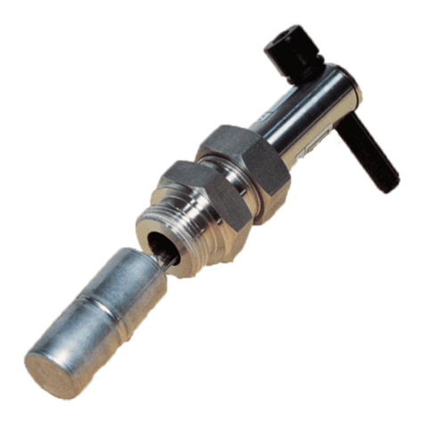
Kobold NV Series User manual
Kobold
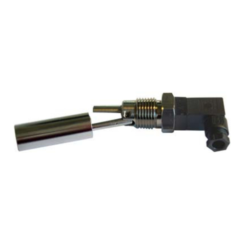
Kobold RFS User manual
Kobold
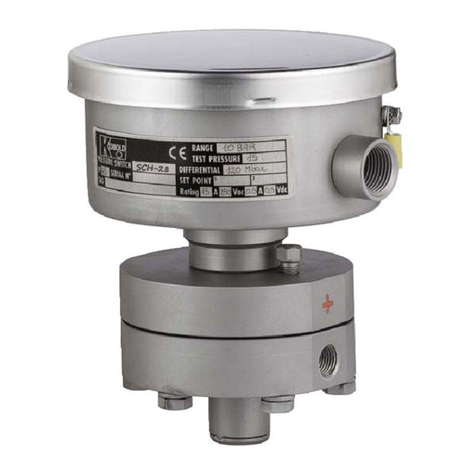
Kobold SCH-27 User manual
Kobold
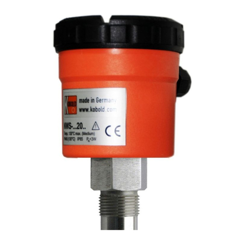
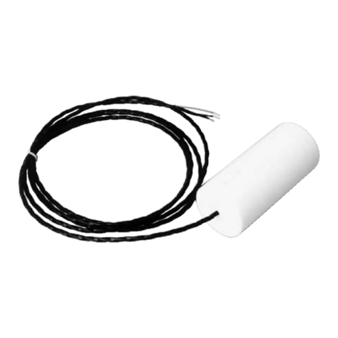
Kobold NWS-5225 Installation instructions
Kobold
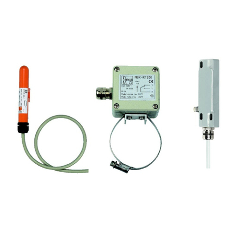
Kobold NST User manual
Kobold
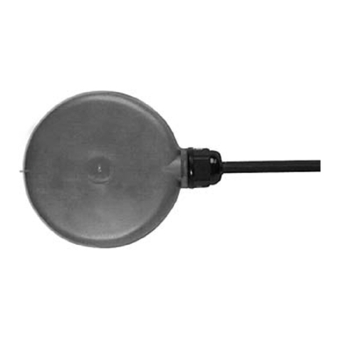
Kobold NBK-R series User manual
Kobold
Kobold NSM User manual

Kobold
Kobold PSC series User manual

Kobold
Kobold PSR User manual

Kobold
Kobold BVO Series User manual

Kobold
Kobold NBK-RA User manual

Kobold
Kobold LNK User manual

Kobold
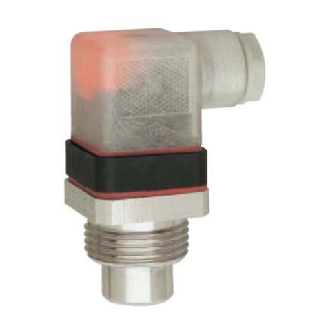
Kobold NE-104 User manual
Kobold
Kobold TWR User manual

Kobold
Kobold TDD User manual

Kobold
Kobold NAB User manual

Kobold
Kobold KAL-8115FL User manual

Kobold
Kobold NCG NCM Series User manual
Kobold
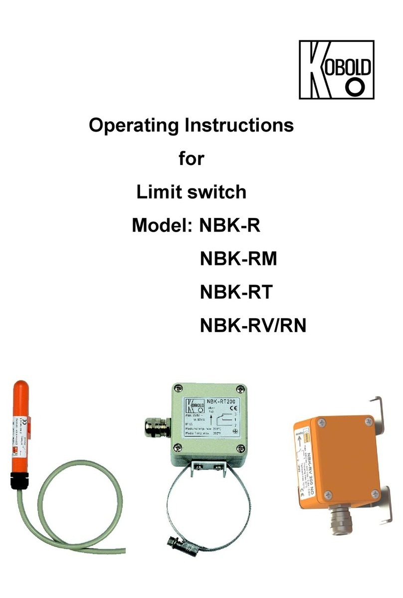
Kobold NBK-R User manual

Kobold
Kobold NAS User manual
Popular Switch manuals by other brands

SMC Networks
SMC Networks SMC6224M Technical specifications

Aeotec
Aeotec ZWA003-S operating manual

TRENDnet
TRENDnet TK-209i Quick installation guide

Planet
Planet FGSW-2022VHP user manual

Avocent
Avocent AutoView 2000 AV2000BC AV2000BC Installer/user guide

Moxa Technologies
Moxa Technologies PT-7728 Series user manual

Intos Electronic
Intos Electronic inLine 35392I operating instructions

Cisco
Cisco Catalyst 3560-X-24T Technical specifications

Asante
Asante IntraCore IC3648 Specifications

Siemens
Siemens SIRIUS 3SE7310-1AE Series Original operating instructions

Edge-Core
Edge-Core DCS520 quick start guide

RGBLE
RGBLE S00203 user manual
