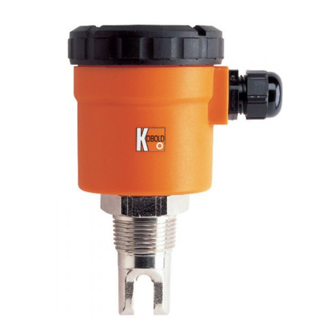
Kobold LNK-K User manual

Operating Instruction
for
Conductive Level Switch
Model: LNK-K

LNK-K
Page 2 LNK-K K06/0422
1. Contents
1.Contents ........................................................................................................ 2
2.Note .............................................................................................................. 3
3.Instrument Inspection .................................................................................... 3
4.Regulation Use ............................................................................................. 3
5.Operating Principle ........................................................................................ 4
5.1.External electrode relay (e.g. NE-104, 304) ......................................... 4
6.Mechanical Connection ................................................................................. 4
6.1.Welding details for sleeves LZE ........................................................... 5
6.2.Installation in G1/2 thread .................................................................... 6
7.Electrical Connection .................................................................................... 7
7.1.Plug assignment of M12-plug without switching electronics ................ 7
7.2.Plug assignment of M12-plug with switching electronics ..................... 7
8.Technical Information .................................................................................... 9
9.Order Codes ............................................................................................... 10
10.Maintenance ............................................................................................... 10
11.Dimensions ................................................................................................. 11
12.EU Declaration of Conformance ................................................................. 12
Manufactured and sold by:
Kobold Messring GmbH
Nordring 22-24
D-65719 Hofheim
Tel.: +49(0)6192-2990
Fax: +49(0)6192-23398
E-Mail: [email protected]
Internet: www.kobold.com

LNK-K
LNK-K K06/0422 Page 3
2. Note
Please read and take note of these operating instructions before unpacking and
setting the unit for operation, and follow the instructions precisely as described
herein.
The instruction manuals on our website www.kobold.com are always for currently
manufactured version of our products. Due to technical changes, the instruction
manuals available online may not always correspond to the product version you
have purchased. If you need an instruction manual that corresponds to the
purchased product version, you can request it from us free of charge by email
([email protected]) in PDF format, specifying the relevant invoice number and
serial number. If you wish, the operating instructions can also be sent to you by
post in paper form against an applicable postage fee.
The devices are only to be used, maintained and serviced by persons familiar
with these operating instructions and with the prevailing regulation applying to
procedural safety and the prevention of accidents.
By usage in machines, the measuring unit should be used only then when the
machines fulfil the EC-machine guide lines.
3. Instrument Inspection
Instruments are inspected before shipping and sent out in perfect condition.
Should damage to a device be visible, we recommend a thorough inspection of
the delivery packaging. In case of damage, please inform your parcel service /
forwarding agent immediately, since they are responsible for damages during
transit.
Scope of delivery:
The standard delivery includes:
Conductive Level Switch model: LNK-K
4. Regulation Use
Any use of the Conductive Level Switch, model: LNK-K, which exceeds the
manufacturer’s specification, may invalidate its warranty. Therefore, any resulting
damage is not the responsibility of the manufacturer. The user assumes all risk
for such usage.

LNK-K
Page 4 LNK-K K06/0422
5. Operating Principle
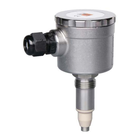
The conductive KOBOLD level probes LNK-K are used for level measurement.
The electrical resistance between metallic vessel and level electrode is measured
and evaluated. In combination with the KOBOLD LZE or LZE-R weld-in sleeves,
the probe provides a measuring point that has no dead space and meets hygiene
standards and (EHEDG approval certificate). This level switch is therefore very
well suited for CIP/SIP cleaning and because of its compact design the device is
suitable for almost every measurement.
The KOBOLD probes LNK-K are also available with integrated evaluating
electronics. The output signal (24 VDC) can thus be connected to a PLC for
evaluation. This means lower installation costs, minimum wiring requirements and
a high degree of noise immunity.
The level probes are connected electronically through an M12x1 plug connection.
Different stem lengths are available. The stem may also be E-CTFE coated, so
that foaming media can be detected.
5.1. External electrode relay (e.g. NE-104, 304)
When the LNK-K is used as a 1-stem probe, the evaluation can take place with
an external electrode relay.
For connection and adjustment please see instruction manual of the external
electrode relay.
6. Mechanical Connection
The electrodes must be mounted in a vertical position in the lid or the ground
of the vessel which must be detected.
The mounting must be done in a way that the electrode stem does not contact
the wall of the vessel.
Note during mounting that the electrodes do not bend and the medium can
drain off easily when they are not longer touched by the fluid.
Shortening the electrodes:
The electrode tip corresponds to the switching point and can be shortened if
desired.
Note, that the bracing of the electrode in the thread-piece is not too heavily
loaded during shortening.
Do not harm the isolation of the electrode.
After shortening, make sure that the E-CTFE isolation is removed of about a
length of 5 mm from the tip of the electrode.

LNK-K
LNK-K K06/0422 Page 5
6.1. Welding details for sleeves LZE
Welding in tanks and pipes:
1. Drill a hole with a diameter equivalent to outer diameter of the sleeve; max.
tolerance +0,2 mm
2. Weld the sleeve at 4 points
3. Screw in the blind socket
4. Weld the sleeve segments crosswise between already welded 4 points.
4 sleeve segments for M12 and G 1/2”; 8 sleeve parts for G1”
Attention! In order to avoid deforming or red-hot turning of the
sleeve, pauses between individual sleeve segments should be
sufficient enough to allow cooling down of the sleeve.
Pay attention to the maximum allowable torque of 10 – 15 Nm (instrument
connection G1/2) when you screw in the sensor.
Please avoid screwing in and unscrewing the sensor from the sleeve, because
on high stress the sealing edge can distort and the process connection can get
leaky.
The sealing system is designed for CIP- and SIP-cleaning.

LNK-K
Page 6 LNK-K K06/0422
6.2. Installation in G1/2 thread
If the sleeve LZE is not used for the installation of the level switch LNK-K, it is
possible to seal the screw thread with an adequate sealing material. Thus an
installation is possible in a pipe as well as in a vessel.
For this type of installation please take care that there is a conducting connection
to the wall of the vessel.
An additional grounding to the pipework (wall of the vessel) is necessary when
using an isolating sealing.

LNK-K
LNK-K K06/0422 Page 7
7. Electrical Connection
Attention! Make sure that the voltage values of your system
correspond with the voltage values of the measuring unit.
Make sure that the supply wires are de-energised.
Connect the supply wires and the output signal to the shown pins.
We recommend the use of wires with cross sectional area of min. 0,25 mm²
Attention! A wrong connection of the plug pins can damage the
unit’s electronic!
7.1. Plug assignment of M12-plug without switching electronics
1 Electrode 1
2 not connected
3 earthing of housing
4 not connected
7.2. Plug assignment of M12-plug with switching electronics
1 Power Supply + Vs / GND
2 Sensitivity + Vs / GND / open
3 Power Supply GND / +Vs
4 Output: Transistor PNP
21
34
21
34

LNK-K
Page 8 LNK-K K06/0422
7.2.1. Setting the output function with the option switching electronics:
The output function (full / empty signal) is switchable by changing the polarity of
the supply voltage.
Power suppl
y
Probe Output
Plug PIN 4
Plu
g
PIN 1 Plu
g
PIN 3
GND + Vs immersed Uout
dr
y
0 V
+ Vs GND immersed 0 V
dr
y
Uout
7.2.2. Setting the sensitivity with the option switching electronics:
1. Configurate the instrument according to sensitivity step 1.
2. Cover probe with the medium to be measured.
3. If the output does not switch, try steps 2 and3 in succession.
Step Sensitivity Plug PIN 2
1 2 k + Vs
2 20 k open (not connected)
3 200 k GND

LNK-K
LNK-K K06/0422 Page 9
8. Technical Information
Measuring principle: conductive
Process temperature: -20...+100 °C
(temporary 150 °C for CIP-process)
Ambient temperature: 0...70 °C
Operating pressure: max. 10 bar
Material
• Head, thread supports: stainless steel 1.4404
• Insulating section: PEEK
• Electrode stem: stainless steel 1.4404
• Stem coating: E-CTFE, coating 0.3 mm
Electrode length: 100, 250, 500, 750, 1000,
1500 mm
Process connection: G 1/2,
hygienic weld-in sleeves
LZE or LZE-R
Electrical connection: M12x1 plug connector
Protection: IP 67
Weight: approx. 150 g (+ special stem)
Switching electronics:
Power supply: 15...36 VDC , 15 mA
Electrode voltage: 2 VAC , 500 Hz sensitivity
(adjustable): 3 steps 2.0 / 20 / 200 kΩ
Function: Full /empty report (switchable via
the polarity of the supply voltage)
Output: PNP, open collector,
U
out = Vvers. - 1.0 V
max. 50 mA, short-circuit-proof
Switch delay: 1 s

LNK-K
Page 10 LNK-K K06/0422
9. Order Codes
Example order: LNK-K 2 0 A 00S
Model Design Electrode
material
Electrode
coatin
g
Electrode
len
g
th
Electrical connection
Evaluation
LNK- K = compact
version 2 = st. steel 1.4404
0 = without
coating
E = E-CTFE-
coating
A = 4 mm stump
B = 100 mm
C = 250 mm
D = 500 mm
E = 750 mm
F = 1000 mm
G= 1500 mm
00S = without electronics,
M12x1-Stecker,
4 pole
NPS = switch electronics,
PNP-switch output
M12x1 plug,
4 pole
EHEDG certification of the connection system in combination with built-in sleeve LZE
10. Maintenance
The Conductive Level Electrodes work completely maintenance free.
Occasionally, the electrode tips should be checked for deposits or corrosion and
cleaned accordingly. Insulated layers can result in false alarms.

LNK-K
LNK-K K06/0422 Page 11
11. Dimensions
with switching electronics without switching electronics

LNK-K
Page 12 LNK-K K06/0422
12. EU Declaration of Conformance
We, KOBOLD-Messring GmbH, Hofheim-Ts, Germany, declare under our sole
responsibility that the product:
Conductive Level Switch Model: LNK-K
to which this declaration relates is in conformity with the standards noted below:
EN 61326-1: 2013
Electrical equipment for measurement, control and laboratory use - EMC
requirements - Part 1: General requirements
EN IEC 63000:2018 Technical documentation for the assessment of electrical
and electronic products with respect to the restriction of hazardous substances
Also, the following EC guidelines are fulfilled:
2014/30/EU EMC Directive
2011/65/EU RoHS (category 9)
2015/863/EU Delegated Directive (RoHS III)
We confirm that the materials used are fully suitable for direct contact with food
and comply with EC Regulation
1935/2004
10/2011,
and (FDA) CFR21.
Hofheim, 13 April 2022
H. Volz M. Wenzel
General Manager Proxy Holder
Table of contents
Other Kobold Switch manuals

Kobold
Kobold NE-104 User manual

Kobold
Kobold PSD User manual

Kobold
Kobold AFS-G3 User manual

Kobold
Kobold TDD Series User manual

Kobold
Kobold NBK-R User manual

Kobold
Kobold NSED User manual

Kobold
Kobold M Series User manual

Kobold
Kobold NSV Series User manual

Kobold
Kobold NBK-RPVC User manual
Kobold
Kobold NWS User manual
Popular Switch manuals by other brands

Blackbe;rry
Blackbe;rry SWITCH DEVICE user guide

Rose electronics
Rose electronics Ultraview Pro UKT-KVM-1U08-Z Quick installation guide

D-Link
D-Link xStack DGS-3612G series Specifications

Radial Engineering
Radial Engineering BigShot i/o owner's manual

National Instruments
National Instruments NI 9344 Getting started guide

Pylon Technologies
Pylon Technologies LV-Hub product manual