Kobold MFR-00 User manual

Operating Instructions
for
Magnetic Filter
Model: MFR-00

MFR-00
page 2 MFR-00 K01/0913
1. Contents
1.
Contents........................................................................................................2
2.
Note ..............................................................................................................3
3.
Instrument Inspection....................................................................................3
4.
Regulation Use .............................................................................................3
5.
Operating Principle .......................................................................................4
6.
Mechanical Connection.................................................................................4
6.1
Mounting/Disassembly.........................................................................4
6.2
Mounting with threaded connection.....................................................5
7.
Maintenance .................................................................................................7
7.1
Cleaning of the mesh...........................................................................7
8.
Technical Information....................................................................................8
9.
Order Codes .................................................................................................8
10.
Dimensions...................................................................................................9
Manufactured and sold by:
Kobold Messring GmbH
Nordring 22-24
D-65719 Hofheim
Tel.: +49(0)6192-2990
Fax: +49(0)6192-23398
E-Mail: info.de@kobold.com
Internet: www.kobold.com

MFR-00
MFR-00 K01/0913 page 3
2. Note
Please read these operating instructions before unpacking and putting the unit
into operation. Follow the instructions precisely as described herein.
The devices are only to be used, maintained and serviced by persons familiar
with these operating instructions and in accordance with local regulations
applying to Health & Safety and prevention of accidents.
When used in machines, the measuring unit should be used only when the
machines fulfil the EWG-machine guidelines.
as per PED 97/23/EG
3. Instrument Inspection
Instruments are inspected before shipping and sent out in perfect condition.
Should damage to a device be visible, we recommend a thorough inspection of
the delivery packaging. In case of damage, please inform your parcel service /
forwarding agent immediately, since they are responsible for damages during
transit.
Scope of delivery:
The standard delivery includes:
•Magnetic Filter model: MFR
•Operating Instructions
4. Regulation Use
Any use of the Magnetic Filter, model: MFR, which exceeds the manufacturer’s
specification may invalidate its warranty. Therefore, any resulting damage is not
the responsibility of the manufacturer. The user assumes all risk for such usage.

MFR-00
page 4 MFR-00 K01/0913
5. Operating Principle
KOBOLD magnetic filters are used in many applications, including central system
filters, where it is necessary to protect devices from dirt and contamination. They
are used to catch and remove contaminants from industrial cooling and
lubrication circuits, especially where residue and sediment from assembly (such
as chips from thread-cutting) and normal operation (such as scale and residue
from frictional wear) can be carried along in the medium being filtered.
Contaminants of these types can form deposits that can cause pitting and
corrosion in highly sensitive measuring and control devices. Regular
maintenance and cleaning of the magnetic filter inserts will effectively prevent
system and device failure and the resulting downtime.
6. Mechanical Connection
Before mounting:
•Remove all transport safety devices. Observe that there won’t be any parts of
the package in the armature.
•Satisfy yourself that the armatures/vales will only be used within their
admissible limiting value (see technical data).
•After the mechanical connection check the tightness of the connection screw
connection/tube, if possible.
6.1 Mounting/Disassembly
The mechanical mounting is identical in all variants. It differs only by the type of
connection.
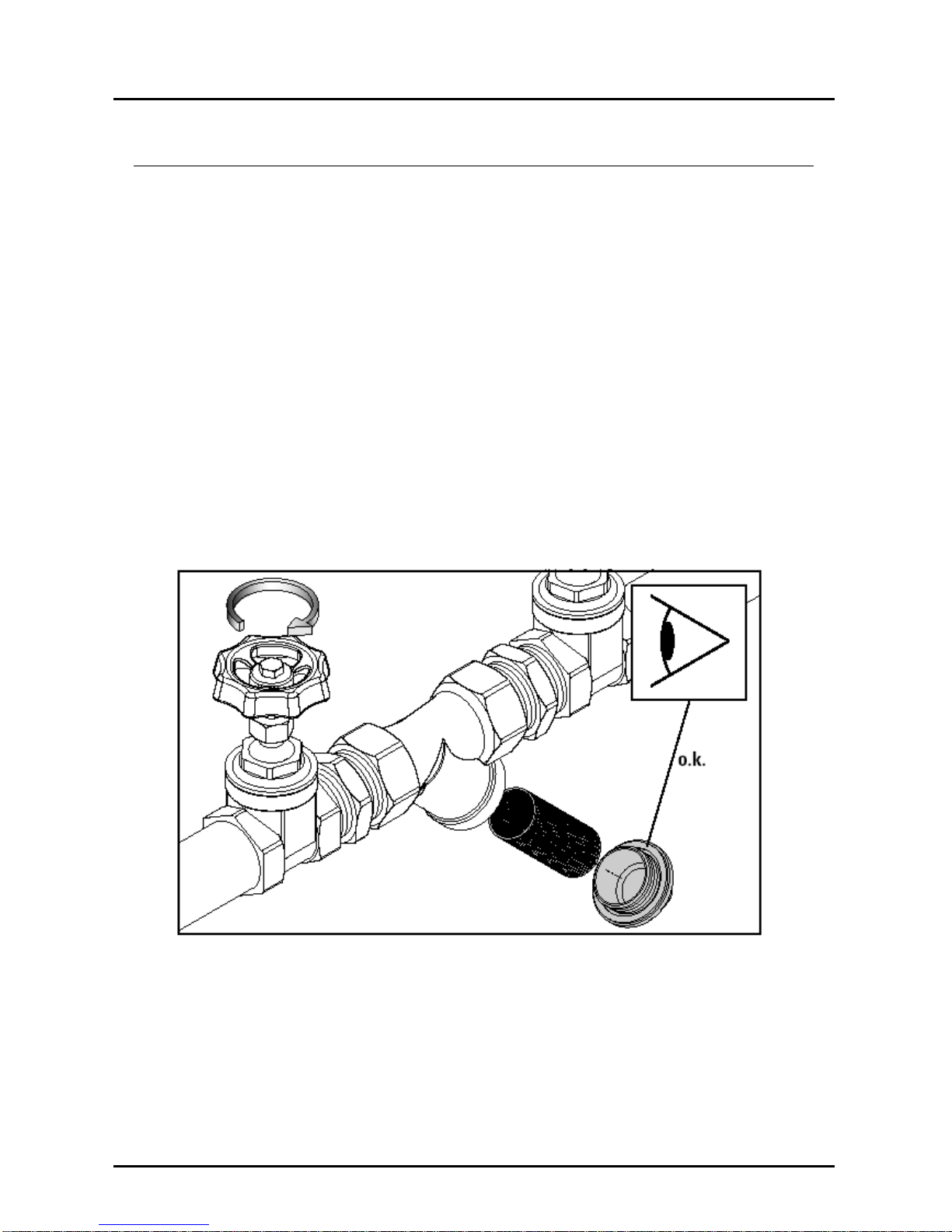
Observe the flow direction which is specified on the valve body. The installation
of the screw joint should take place downwards, that the pollution will fall out of
the body by the cleaning of the y-strainer.
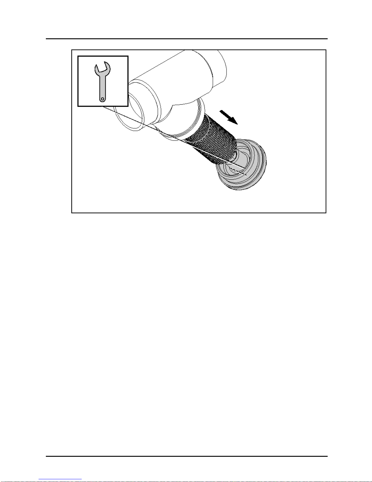
We recommend the installation of a gate valve in front and behind the y-strainer,
to clean the mesh without emptying of the device.
Remove all transport safety devices (e.g. plugs or caps). Observe that there
won’t be any parts of the package or other pollution in the armature.
Before mounting the y-strainer clean up the pipes.
Avoid stress on the body by non align pipes.

MFR-00
MFR-00 K01/0913 page 5
6.2 Mounting with threaded connection
Before lay on sealing compounds, check the hardly screwing of the pipes into the
valve body.
Lay on the correct sealing compounds on the pipe’s end. By using PTFE-ribbon
or hemp sealings observe the screw direction. Don’t use sealing compounds
which are not prescribed for your employment.
Screw the pipes into the connection ends of valve.
Strike up the pipes with pressure after that time the manufacturer of the sealing
compounds pretends for harden it.
Check the tightness of all connections.
Y-strainer, mounting with threaded connection

MFR-00
page 6 MFR-00 K01/0913
Y-strainer, disassemble of the bonnet

MFR-00
MFR-00 K01/0913 page 7
7. Maintenance
Depending on the used media and the employment of the y-strainer you have to
do the following:
•Cleaning of the mesh
7.1 Cleaning of the mesh
Cut of the media flow and relieve the media pressure.
Keep ready some fit tanks to catch up leaking liquids.
Loosen the bonnet of the strainer. Catch up the running out liquid. Take the
bonnet aside and pull the mesh out of the body.
Clean the body and the mesh or exchange the mesh for a new one.
Insert the mesh into the body of the y-strainer.
Screw the bonnet into the body. Observe the correct placement of the seals in
the bonnet and take care that there will be no pollution on the seals or the seat.
Tighten the bonnet with a fit spanner.
Check the tightness of all connections.
Y-strainer, cleaning of the mesh

MFR-00
page 8 MFR-00 K01/0913
8. Technical Information
MFR-00 (brass version)
Thread connection: Female thread G ½…G 3
Nominal pressures
Screw-on magnetic filter: PN 16
Max. temperature
Screw-on magnetic filter: 200 °C
Filter size: see table
Mounting position: Cover toward bottom,
note specified direction of flow
Materials
Body: Brass Ms 58
Cover: Brass Ms 58
Mesh: Stainless steel 1.4301
Gasket: Klinger Sil
®
C-4300
Mesh size: 280 µm up to G 2”
530 µm up to G 3”
9. Order Codes
Dimensions and order details (example: MFR-0015)
Version Connection kV-value
[m³/h]
Filter
size
[µm]
Size of
filter
cartridge
[mm]
L
[mm]
h
[mm]
Weight
[kg] ID no.
Female
thread
G 1/2 6.2 280 19/32 58 44 0.3 MFR-0015
G 3/4 7.7 280 25/38 69 47 0.3 MFR-0020
G 1 12.4 280 29/46 82 56 0.4 MFR-0025
G 1 1/4 13.9 280 37/55 98 68 0.5 MFR-0032
G 1 1/2 18.5 280 43/61 109 78 0.9 MFR-0040
G 2 31 280 58/75 131 98 2.2 MFR-0050
G 2 1/2 56 530 66/9 151 114 2.8 MFR-0065
G 3 80 530 80/130 172 129 4.8 MFR-0080

MFR-00
MFR-00 K01/0913 page 9
10.Dimensions
Magnetic filter, female thread, MFR-
G
Table of contents
Other Kobold Water Filtration System manuals
Popular Water Filtration System manuals by other brands

JRC
JRC NSVS1129 manual

Antunes
Antunes VZN-421H owner's manual

Clean Water Systems
Clean Water Systems Fleck 9100 Installation & start-up manual

Kinetico
Kinetico POWERLINE PRO Series owner's manual

clage
clage Zip KXF 2.1 Operating and installation instructions

AquaScape
AquaScape 77020 Installation instructions & maintenance