Kockum Sonics AB, Industrigatan 39, P.O. Box 1035, SE-212 10 Malmö, Sweden, Tel: +46 (0) 40 671 88 00
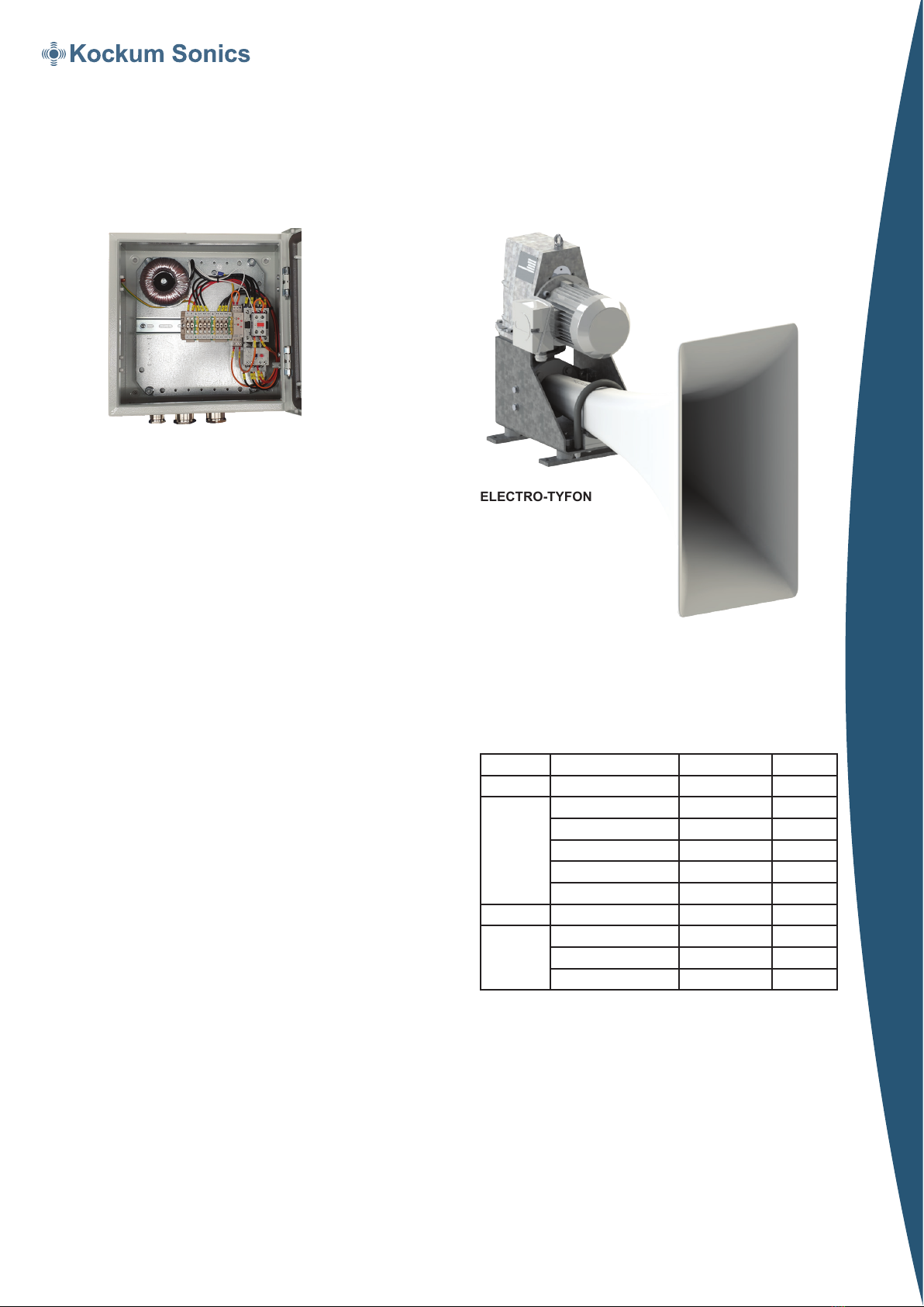
ELECTRO–TYFON®MT 150/130
For vessels of 75 m to 200 m in length
TYFON®
KSM520E/2220
Contactor Unit TK 80
See separate leaflet KSM742
Sound frequency (basic): 130 Hz
Sound Pressure Level
acc to IMO (1/3 oct band): >138 dB/1m
Sound Level A-weighted: 142 dBA/1m
Electrical protection class: IP 56
Colors:
Body Galvanized nat.
Motor Grey RAL 7030
Horn White RAL 9003
Weight (approx.): 68 kg
General Information
ELECTRO–TYFON®MT 150/130 is an electrically driven
piston ship’s whistle. It is built up of comparatively few
moving parts as the “swinging piston”, no lubricated cylinder
and an oil free gearbox.
Important features:
• unsymmetrical sound distribution
• operates in all ambient temperatures without any
additional measures
• unaected by voltage and frequency uctuations
• oil free, maintenance free and non–corrosive
• easy to install
• complies fully with the International Regulations
IMO 1972 Technical Data
ELECTRO-TYFON
Operates in all temperatures without any
additional measures
ELECTRO–TYFON®MT 150/130 will give a high
performance in both arctic and tropical climates.
A patented system with a high eciency rectangular
horn and a specially designed motor will match the motor
speed to the acoustic resonance of the horn at any
ambient temperature without any additional measures.
This system also prevents the whistle from being aected
by voltage and frequency uctuations in onboard mains.
Unsymmetrical Sound Distribution
The IMO Regulations stipulate a very high Sound
Pressure Level for ecient signaling, yet the sound level
of the vessel's own signal at the listening posts shall not
exceed 110 dBA.
A common way to solve this “paradox” is to place the
whistle very high above deck. But what if the highest point
is not high enough? For example: to reduce the noise
from the signal by 6 dB, the distance between the
listening post and the whistle must be doubled!
ELECTRO–TYFON®MT 150/130 with Unsymmetrical
Sound Distribution is the solution. The horn with its unique
vertically extended front, and a specially created sound
spectrum will reduce the noise on deck with 6–8 dB
compared to a conventional whistle with circular orice.
Type Power Supply Rated current Ref. No.
MT150/130 3ph440V60Hz(+-10%) 11A 24800171
3ph230V60Hz(+-10%) 20A 24800935
3ph380V50Hz(+-10%) 11,5A 24800498
3ph230V50Hz(+-10%) 22A 24800936
3ph690V60Hz(+-10%) 5,5A 24800543
3ph690V50Hz(+-10%) 6 A 24800544
MT150/140 3ph440V60Hz(+-10%) 11A 24800569
3ph380V50Hz(+-10%) 20A 24800570
3ph690V60Hz(+-10%) 5,5A 24800571
3ph690V50Hz(+-10%) 6A 24800572


