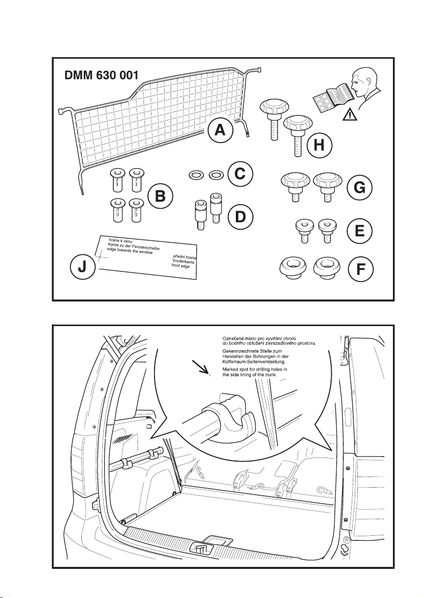
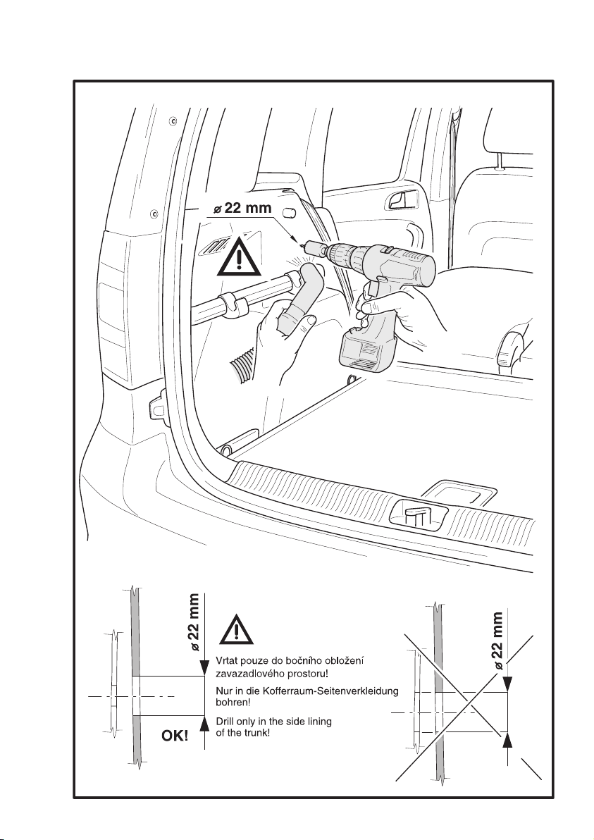
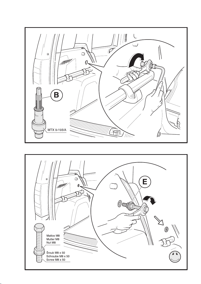
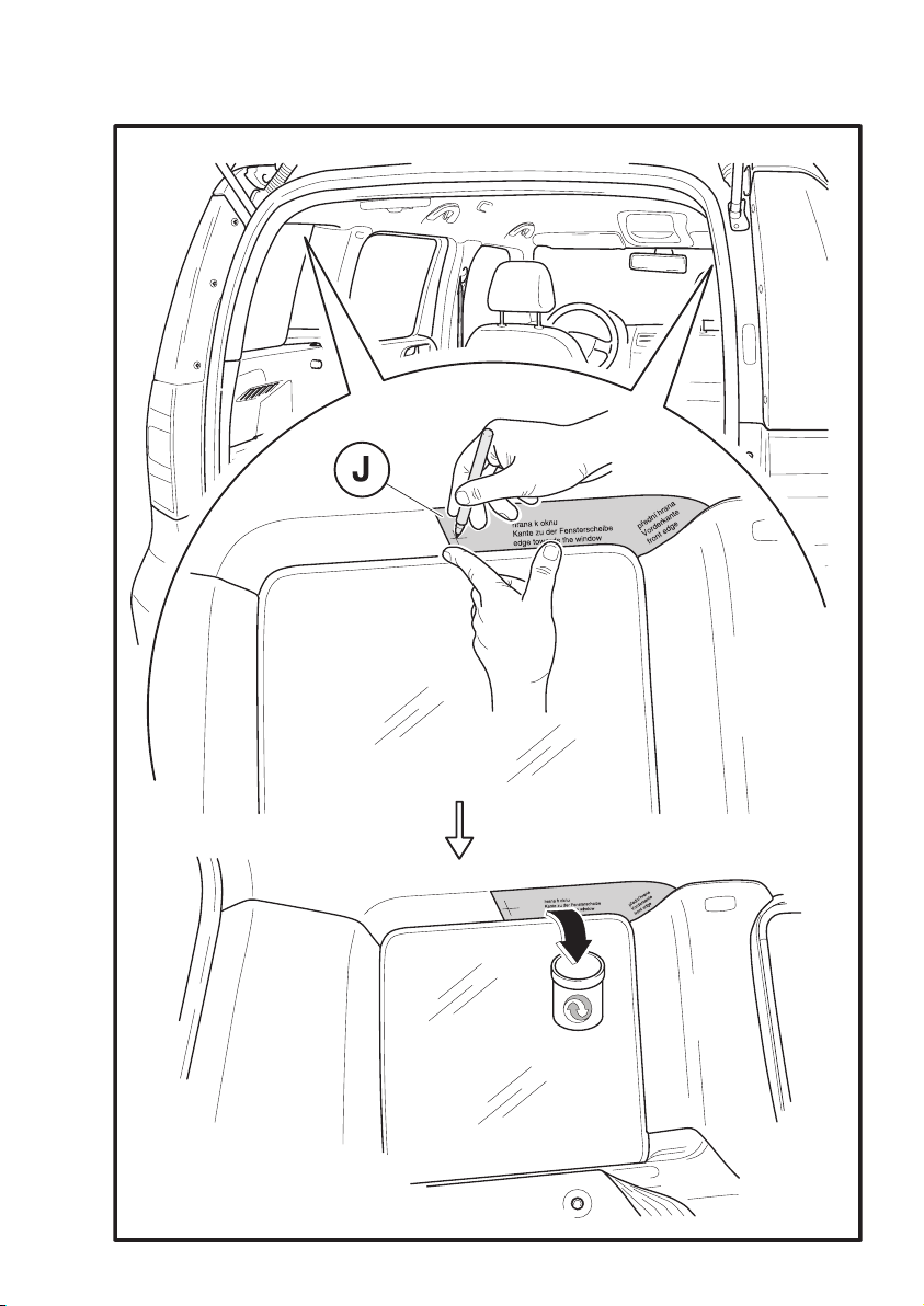
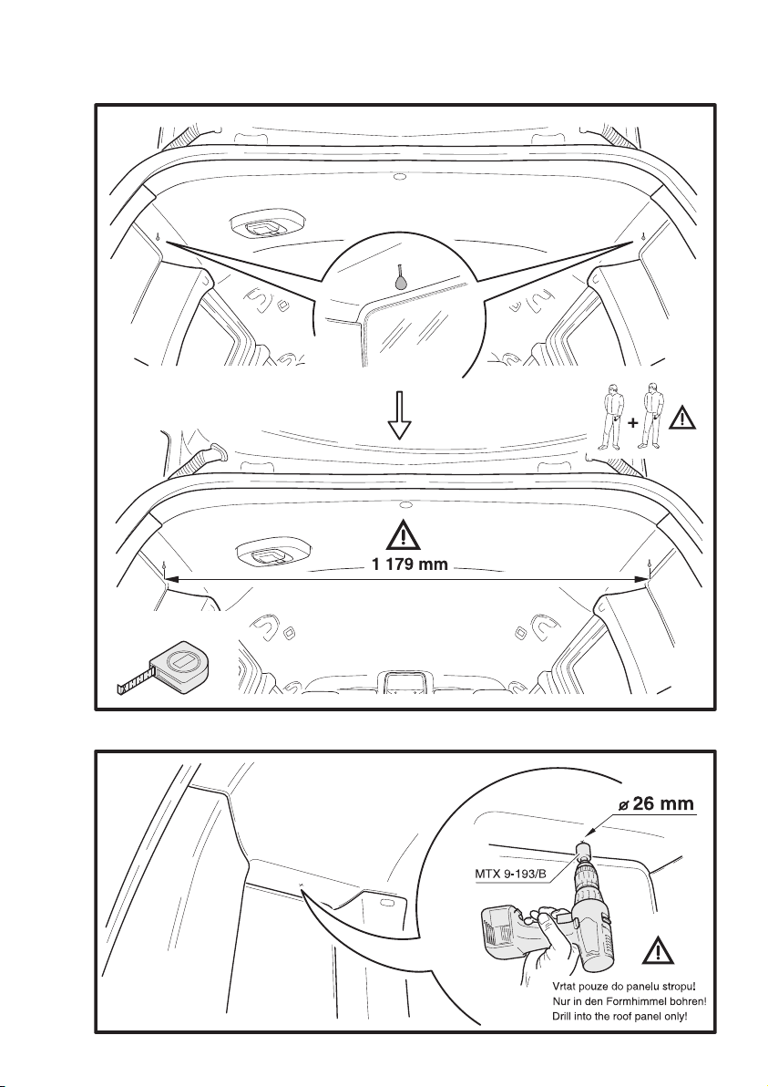
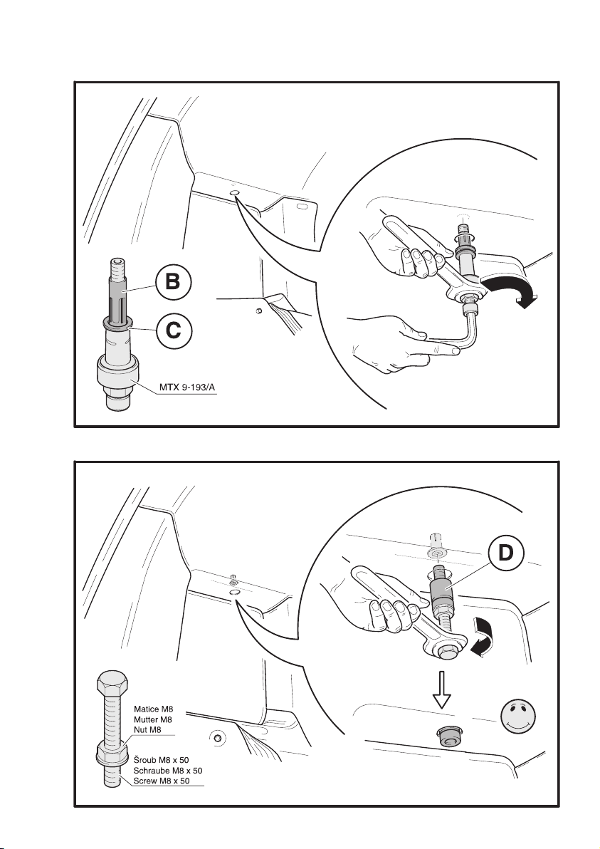
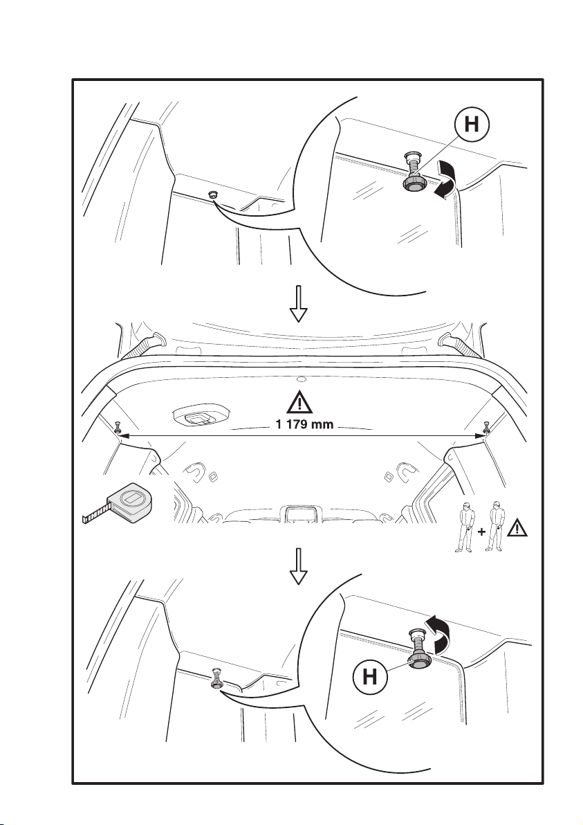
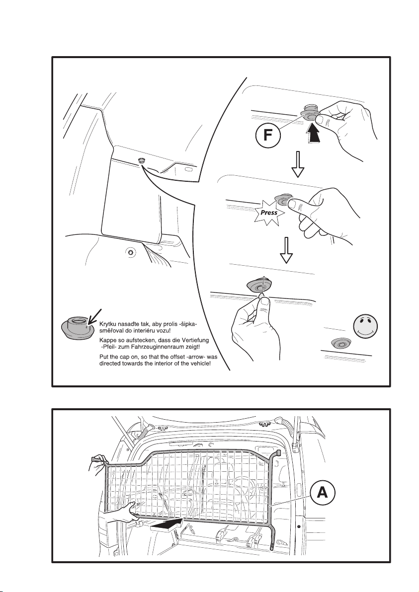
KODA Yeti Trunk grille User manual

Objednací číslo/ Bestellnummer/ Order Number
ŠKODA Originální příslušenství®
ŠKODA Original Zubehör®
ŠKODA Genuine Accessories®
Yeti (5L)
Montážní návod/ Montageanleitung/ Fitting instructions
DMM 630 001
Dělicí mříž
Trenngitter
Trunk grille
SIMPLY CLEVER


1
2

3

4
5

6

7
8

9
10

11

12
13

14
15


CZ
DĚLICÍ MŘÍŽ
Produkty příslušenství jsou určeny k odborné montáži. Škoda Auto doporučuje provádět
montáž u smluvních partnerů.
Upozornění. Dělicí mříž nelze použít do vozů, ve kterých je namontováno nezávislé to-
pení (z důvodu kolize úchytu dělicí mříže s řídicí jednotkou dálkového ovládání nezá-
vislého topení).
Postup montáže
Vyjměte kryt zavazadlového prostoru z vozu a sklopte opěradla zadních sedadel.
Dělicí mříž namontujte dle obrázků v návodu. Všechny pokyny pro namontování dělicí
mříže provádějte na obou stranách vozu stejným způsobem.
Při operaci vrtání pečlivě vysávejte vzniklé třísky, aby nedošlo k poškození interiéru
vozu.
Poznámka. Pokud dojde ke ztrátě nýtovacích matic, je možné je doobjednat z katalogu
Škoda originálního příslušenství pod číslem dílu 5L6 071 754.
Seznam speciálního nářadí
Přípravek pro nanýtování nýtovacích matic (B) (do otvorů v plechu karoserie pod obložením
zavazadlového prostoru a do otvorů v postranici střechy pod panelem stropu):
- MTX 9-193/A, stranový klíč OK 13 , imbus klíč č. 10
Přípravek pro vyvrtání otvorů do panelu stropu mezi C-sloupkem a D-sloupkem vozu:
- MTX 9-193/B
Přípravek pro našroubování mezikusů (D) a (E):
- Šroub M8 x 50, samojistná matice M8.
Čalounické špendlíky, tužka, metr
Upozornění k obrázkům
Upevňovací body pro uchycení dělicí mříže v bočním obložení zavazadlového prostoru
(obr. 2 - 5)
- Místo pro vrtání otvoru do obložení zavazadlového prostoru je označeno již z výroby malým
bodem.
- Otvory o průměru 22 mm vyvrtejte pouze do bočního obložení zavazadlového prostoru.
- Nýtovací matice (B) nanýtujte pomocí přípravku MTX 9-193/A do otvorů v plechu ka-
roserie pod obložením zavazadlového prostoru následovně:
- nýtovací matici (B) nasaďte na nýtovací přípravek,
- přípravek s nasazenou nýtovací maticí vložte do otvoru v karoserii,
- postupným utahováním matice na šroubu nýtovací matici nanýtujte,
- matici na šroubu dotáhněte nadoraz, jinak bude nýtovací matice volná,
- povolte matici a přípravek vyšroubujte.

CZ - Mezikusy (E) našroubujte pomocí šroubu M8 x 50 a samojistné matice M8 následují-
cím způsobem:
- mezikus našroubujte na šroub,
- samojistnou matici dotáhněte k mezikusu,
- přípravek s mezikusem vložte do otvoru v nanýtované matici a mezikus zašroubujte.
- povolte samojistnou matici a šroub vyšroubujte.
Upevňovací body pro uchycení dělicí mříže v panelu stropu mezi C-sloupkem a
D-sloupkem vozu (obr. 6 - 12)
- Šablonu (J) pro označení otvoru do panelu stropu mezi C-sloupkem a D-sloupkem vozu
ustavte pečlivě dle popisu na šabloně.
- Označte místa pro budoucí otvory.
- Do označených míst zapíchněte čalounické špendlíky a zkontrolujte tak polohu budoucích
otvorů (jsou-li pod otvory v postranici střechy).
- Rozteč otvorů zkontrolujte měřením.
- Odstraňte čalounické špendlíky a do panelu stropu vyvrtejte otvory o průměru 26 mm
(použijte přípravek MTX 9-193/B).
- Nýtovací matice (B) s podložkou (C) nanýtujte do otvorů v postranici střechy pod pa-
nelem stropu pomocí nýtovacího přípravku MTX 9-193/A. Postupujte stejným způsobem
jako u nýtování matic do otvorů v karoserii pod bočním obložením zavazadlového prostoru.
Postup viz. výše.
- Mezikusy (D) našroubujte pomocí šroubu M8 x 50 a samojistné matice M8 a pečlivě
je dotáhněte. Postupujte stejným způsobem jako u našroubování mezikusů (E). Postup
viz. výše.
- Do mezikusů zašroubujte šrouby s plastovou hlavou (H) a znovu měřením překontroluj-
te rozteč otvorů pro uchycení dělicí mříže. Je-li rozteč otvorů správná, šrouby vyšroubujte a
na mezikusy nasaďte krytky (F). Nesouhlasí-li rozteč otvorů, pak mírným tlakem na zašrou-
bovaný šroub upravte vzdálenost na správnou hodnotu.
- Při nasazení krytek (F) dbejte na to, aby nedošlo k deformaci panelu stropu. Je-li u kry-
tek panel stropu nerovný, vytáhněte a srovnejte jej pomocí čalounického špendlíku. Krytky
ustavte tak, aby jejich širší část byla směrem k oknu (tzn. prolis na krytce musí směřovat do
interiéru vozu).
Uchycení dělicí mříže (obr. 13 - 14)
- Vložte dělicí mříž do zavazadlového prostoru vozu a ustavte ji k připraveným upevňovacím
bodům. Pomocí šroubů s plastovou hlavou (G, H) ji upevněte. Šrouby rukou dotáhněte na
doraz.
Opěradla zadních sedadel sklopte zpět do standardní polohy.
Kryt zavazadlového prostoru namontujte zpět do vozu dle pokynů v návodu Dělicí mříž - na-
sazení (vyjmutí) krytu zavazadlového prostoru DMM 630 012. Návod nasazení (vyjmutí) krytu
zavazadlového prostoru předejte zákazníkovi.

DE
TRENNGITTER
Die Zubehörprodukte sind für eine fachmännische Montage vorgesehen. Škoda Auto emp-
fiehlt es, die Montage von einem Vertragspartner durchführen zu lassen.
Hinweis. Das Trenngitter kann nicht für Fahrzeuge mit verbauter Standheizung ver-
wendet werden (wegen einer Kollision der Trenngitteraufnahme mit dem Steuergerät
für die Funkfernbedienung der Standheizung).
Montageablauf
Die Kofferraumabdeckung aus dem Fahrzeug herausnehmen und die Rücksitzlehnen
vorklappen.
Das Trenngitter laut Abbildungen in der Anleitung einbauen. Alle Anweisungen für die
Befestigung des Trenngitters auf den beiden Fahrzeugseiten identisch ausführen.
Beim Bohren die entstandenen Späne sorgfältig absaugen, um Beschädigungen im
Fahrzeuginnenraum zu vermeiden.
Anmerkung. Sollten die Nietmuttern verloren gehen, können sie aus dem Katalog von
Škoda Originalzubehör unter der Teilenummer 5L6 071 754 nachbestellt werden.
Liste der Spezialwerkzeuge
Werkzeug zum Annieten von Nietmuttern (B) (in die Öffnungen im Karosserieblech unter der
Kofferraumverkleidung und in die Öffnungen im Dach-Seitenteil unter dem Formhimmel):
- MTX 9-193/A, Gabelschlüssel SW 13, Imbusschlüssel Nr. 10
Werkzeug zum Herstellen von Bohrungen im Formhimmel zwischen der C- und D-Säule des
Fahrzeugs:
- MTX 9-193/B
Werkzeug zum Einschrauben von Zwischenstücken (D) und (E):
- Schraube M8 x 50, selbstsichernde Mutter M8.
Anstecker, Bleistift, Metermaß
Hinweise zu den Abbildungen
Die Befestigungspunkte zur Befestigung des Trenngitters in der Kofferraum-Seitenver-
kleidung (Abb. 2 – 5)
- Die Stelle zum Herstellen der Bohrung in der Kofferraumverkleidung ist bereits ab Werk mit
einem kleinen Punkt gekennzeichnet.
- Bohrungen mit 22 mm Durchmesser nur in der Kofferraum-Seitenverkleidung herstellen.
- Nietmuttern (B) mit dem Werkzeug MTX 9-193/A in die Öffnungen im Karosserieblech
unter der Kofferraumverkleidung folgendermaßen annieten:
- Nietmutter (B) in das Nietwerkzeug einsetzen,
- Werkzeug mit eingesetzter Nietmutter in die Öffnung in der Karosserie einführen,
- Nietmutter durch langsames Anziehen der Mutter an der Schraube annieten,
- Mutter an der Schraube bis Anschlag anziehen, ansonsten bleibt die Mutter locker,
- Mutter lösen und das Werkzeug herausschrauben.

DE
- Zwischenstücke (E) mit Hilfe der Schraube M8 x 50 und der selbstsichernden Mutter
M8 folgendermaßen anschrauben:
- Zwischenstück auf die Schraube schrauben,
- selbstsichernde Mutter zu dem Zwischenstück anziehen,
- Werkzeug mit dem Zwischenstück in die Öffnung in der angenieteten Mutter einsetzen und
das Zwischenstück einschrauben,
- selbstsichernde Mutter lösen und Schraube herausschrauben.
Die Befestigungspunkte zur Befestigung des Trenngitters im Formhimmel zwischen der
C- und D-Säule des Fahrzeugs (Abb. 6 – 12)
- Schablone (J) zum Kennzeichnen der Öffnung im Formhimmel zwischen der C- und
D-Säule des Fahrzeugs sorgfältig laut Beschreibung auf der Schablone positionieren.
- Stellen für die zukünftigen Öffnungen kennzeichnen.
- Anstecker in die gekennzeichneten Stellen einstechen und dadurch die Stellung der
zukünftigen Öffnungen überprüfen (ob sie sich unter den Öffnungen im Dach-Seitenteil
befinden).
- Abstand der Öffnungen durch einen Messvorgang überprüfen.
- Anstecker entfernen und Bohrungen mit 26 mm Durchmesser im Formhimmel herstellen
(dazu das Werkzeug MTX 9-193/B verwenden).
- Nietmuttern (B) mit Scheibe (C) in die Öffnungen im Dach-Seitenteil unter dem Form-
himmel mit dem Nietwerkzeug MTX 9-193/A annieten. Auf die gleiche Weise wie beim An-
nieten der Muttern in die Öffnungen in der Karosserie unter der Kofferraum-Seitenverklei-
dung vorgehen. Die Vorgehensweise siehe oben.
- Zwischenstücke (D) mit Hilfe der Schraube M8 x 50 und der selbstsichernden Mutter M8
anschrauben und gründlich festziehen. Auf die gleiche Weise wie beim Anschrauben der
Zwischenstücke (E) vorgehen. Die Vorgehensweise siehe oben.
- Kunststoffkopf-Schrauben (H) in die Zwischenstücke einschrauben und den Abstand
der Öffnungen zur Befestigung des Trenngitters durch einen Messvorgang erneut überprü-
fen. Ist der Abstand der Öffnungen i. O., die Schrauben herausschrauben und die Kappen (F)
auf die Zwischenstücke aufstecken. Stimmt der Abstand der Öffnungen nicht überein, dann
den Abstand durch einen leichten Druck auf die eingeschraubte Schraube korrigieren.
- Beim Aufstecken der Kappen (F) darauf achten, dass der Formhimmel nicht verformt wird.
Ist der Formhimmel im Bereich der Kappen uneben, ist er mit dem Anstecker aufzuziehen
und einzuebnen. Die Kappen so positionieren, dass der breitere Teil zur Fensterscheibe
zeigt (d. h. die Vertiefung auf der Kappe muss zum Fahrzeuginnenraum zeigen).
Befestigung des Trenngitters (Abb. 13 - 14)
- Trenngitter in den Fahrzeug-Kofferraum einsetzen und an den vorbereiteten Befestigung-
spunkten positionieren. Das Gitter mit Kunststoffkopf-Schrauben (G, H) befestigen. Die
Schrauben handfest bis Anschlag festziehen.
Die Rücksitzlehnen wieder in die Standardstellung zurückklappen.
Die Kofferraumabdeckung laut Anweisungen in der Anleitung „Trenngitter – Kofferraum-
abdeckung DMM 630 012 einsetzen (herausnehmen)“ wieder in das Fahrzeug einbauen.
Die Anleitung „Kofferraumabdeckung einsetzen (herausnehmen)“ dem Kunden übergeben.

GB
TRUNK GRILLE
The accessories are intended for professional fitting. Škoda Auto recommends the fitting to
be carried out by its contract partners.
Attention. The trunk grille shall not be used in vehicles fitted with a separate heating
(due to collision of the trunk grille fixture and the separate heating remote control unit).
Assembly procedure
Remove the trunk cover from the vehicle and tilt the backrests of the back seats.
Mount the trunk grille as shown on the pictures in the manual. Perform the individual
operations of the trunk grille fitting on both sides of the car in the same way.
During the drilling operation make sure the metal chips are sucked up properly to avoid
damaging the car interior.
Note. If the riveting nuts get lost, they can be ordered from the original Škoda spare
parts catalogue under Part No. 5L6 071 754.
List of special tooling
A preparation to rivet the riveting nuts (B) (into the holes in the body panel under the trunk
carpeting and into the holes in the roof side bearer under the roof panel):
- MTX 9-193/A, spanner OK 13, wrench no. 10
Preparation for drilling holes to the ceiling panel between the C-pillar and the D-pillar of the
vehicle:
- MTX 9-193/B
Preparation for screwing on spacers (D) and (E):
- Screw M8 x 50, self-locking nut M8.
Upholstery pins, pencil, tape measure
Explanation of the figures
The fastening point for mounting the trunk grille in the side trunk carpeting (Fig. 2 - 5)
- Place for drilling a hole into the trunk carpeting is marked with a small point from the manu-
facture.
- Drill holes of 22 mm diameter only into the side lining of the luggage compartment.
- Rivet the riveting nuts (B) using the preparation MTX 9-193/A into the holes of the lid
panel under the lining of the luggage compartment as follows:
- fit the riveting nut (B) on the riveting preparation,
- insert the preparation with the fitted riveting nut into the opening in the carriage body,
- by gradual tightening of the nut on the screw rivet the riveting nut,
- keep tightening the nut on the screw until it stops, otherwise the riveting nut will be lose,
- release the nut and uncsrew the preparation.
- Screw the spacers (E) on using the screw M8 x 50 and the self-locking nut M8 as
follows:
- screw the spacer on the screw,
- tigthen the self-locking nut to the spacer,

GB
- insert the preparation with the spacer into the hole in the riveted nut and screw the
spacer in.
- release the self-locking nut and uncsrew the screw.
Fastening points for fitting the trunk grille in the ceiling panel between the C-pillar and
the D-pillar of the vehicle (Fig. 6 - 12)
- Position the template (J) for marking the hole into the ceiling panel between the
C-pillar and the D-pillar of the vehicle carefully according to the description on the tem-
plate itself.
- Mark the spots for future holes.
- Stab the upholstery pins into the marked spots which allows you to check the position of
future holes (whether they are under the holes in the roof side bearer).
- Check the spacing of the holes by measuring.
- Remove the upholstery pins and drill holes of 26 mm diameter into the ceiling panel (use
preparation MTX 9-193/B).
- Rivet the riveting nuts (B) with washer (C) into the holes of the roof side bearer under the
roof panel, using the riveting preparation MTX 9-193/A. Proceed in the same way as with
riveting the nuts into the holes of the body under the lining of the luggage compartment.
See the procedure as described above.
- Srew the spacers (D) on using the screw M8 x 50 and the self-locking nut M8 and tighten
these properly. Proceed in the same manner as with screwing the spacers (E). See the pro-
cedure as described above.
- Screw the plastic-head screws (H) into the spacers and by measuring re-check the spac-
ing of the holes for fitting the trunk grille. If the spacing of the holes is correct, unscrew the
screws and fit caps (F) on the spacers. If the spacing of the holes does not conform, apply
slight pressure on the screwed-in screw or adjust the distance accordingly.
- When mounting the caps (F) be careful not to deform the panel of the ceiling. If the ceiling
panel appears to be uneven at the caps, pull it out and straighten it using the upholstery pin.
Adjust the caps so that their wider part pointed towards the window (i.e. the offset on the
cap must be directed to the interior of the vehicle).
Fastening of the trunk grille (Fig. 13 - 14)
- Insert he trunk grille into the trunk of the vehicle and adjust it to the prepared fastening
points. Fasten it using the plastic-head screws (G, H). Tighten the screwsb by hand to the
endstop.
Tilt the back-seat rests back to the standard position.
Mount the trunk cover back into the vehicle according to the instructions in the manual Trunk
grille - fitting (removal) of trunk cover DMM 630 012. Pass the fitting (removal) instructions of
the trunk cover on the customer.

ES
REJILLA SEPARADORA
Los accesorios de los productos deben ser montados por profesionales. Škoda Auto reco-
mienda que se realice el montaje en las firmas contratantes.
Advertencia. La parrrilla separadora no se puede usar en los vehículos en los cuales
está montado la calefacción (debido a la colisión del sujetador de la parrilla separadora
con la unidad de control de mando a distancia independiente de la calefacción).
Procedimiento de montaje
Quite la cubierta del compartimiento para equipajes y baje los respaldos de los asien-
tos traseros.
Monte la rejilla separadora tal y como se indica en las figuras en la instrucción. Todas
las instrucciones para montar la rejilla separadora deben cumplirse del mismo modo
por ambos lados del vehículo.
Al barrenar es necesario aspirar las virutas desprendidas para evitar daños del interi-
or del vehículo.
Nota. En caso de que pierda las tuercas remachables, puede encargarlas del catálogo
de accesorios originales de Škoda con el número de pieza 5L6 071 754.
Relación de herramientas especiales
Dispositivo para remachar las tuercas de remache (B) en los orificios de la lámina de la carro-
cería debajo del recubrimiento del compartimiento para equipajes y en los orificios que es-
tán en la parte lateral del techo, debajo del panel del techo):
- MTX 9-193/A, llave acodillada OK 13 , llave Imbus No. 10
Producto para barrenar orificios en el panel del techo entre las columnas C y D del vehículo:
- MTX 9-193/B
El producto para atornillar piezas intermedias (D) y (E):
- Tornillo M8 x 50, tuerca de auto-ajuste M8.
Alfileres de tapicería, lápiz, un metro
Nota referente a las figuras
Puntos de ajuste para fijar la rejilla separadora en la cubierta lateral del comparti-
miento para equipajes (fig. 2 - 5)
- Un punto pequeño marca el lugar donde debe ser barrenado el orificio en la cubierta del
compartimiento para equipajes.
- Orificios de 22 mm. de diámetro deben ser barrenados solo en la cubierta lateral del com-
partimiento para equipajes.
- Para remachar las tuercas de remache (B) en los orificios que están en la lámina de
la carrocería debajo de la cubierta del compartimiento para equipajes emplee el
dispositivo MTX 9-193/A:
- ponga la tuerca de remache (B) sobre el dispositivo remachador,
- inserte en el orificio que está en la carrocería el dispositivo con la tuerca remachadora
puesta
- ajustando consecutivamente la tuerca en el tornillo, remache Vd. la tuerca remachadora,
- ajuste al tope la tuerca en el tornillo, de lo contrario la tuerca remachadora quedaría
suelta,
- desajuste la tuerca, destornille el dispositivo.

ES
- Atornille las piezas intermedias (E) por medio del tornillo M8 x 50 y la tuerca de
auto-ajuste M8 de manera siguiente:
- atornille la pieza intermedia al tornillo,
- ajuste la tuerca de auto-ajuste a la pieza intermedia,
- inserte el dispositivo con pieza intermedia en el orificio de la tuerca remachada, atornille la
pieza intermedia.
- desajuste la tuerca de auto-ajuste y destornille el tornillo.
Puntos de ajuste para fijar la rejilla separadora en el panel del techo entre las colum-
nas del vehículo C y D (fig. 6 - 12)
- Coloque con cuidado el calibre (J) para marcar el orificio en el panel del techo entre las
columnas del vehículo C y D, según las indicaciones en el calibre.
- Marque los puntos de los orificios a barrenar.
- Ponga los alfileres de tapicería en los puntos marcados, revise la posición de los futuros
orificios (a ver si están debajo de los orificios de la parte lateral del techo).
- Mida bien el paso entre los orificios.
- Quite los alfileres de tapicería, barrene en el panel del techo orificios de 26 mm de diámetro
(emplee el dispositivo MTX 9-193/B).
- Remache las tuercas remachadoras (B) con arandela (C) en los orificios que están en
la parte lateral del techo, debajo del panel del techo, utilizando el medio remachador
MTX 9-193/A. Proceda de la misma forma que al remachar tuercas a los orificios en la car-
rocería debajo de la cubierta lateral del compartimiento para equipajes. El procedimiento
véase arriba.
- Atornille las piezas intermedias (D) utilizando el tornillo M8 x 50 y las tuercas de auto-
ajuste M8, ajústelas perfectamente. Proceda de manera igual que al atornillar las piezas
intermedias (E). El procedimiento véase arriba.
- Atornille los tornillos con cabeza plástica (H) en las piezas intermedias y vuelva a medir
el paso entre los orificios que se utilizarán para fijar la rejilla separadora. Si el paso es cor-
recto, entonces destornille los tornillos, ponga tapas (F) en las piezas intermedias. Si el paso
entre los orificios no es correcto, entonces presionando moderadamente el tornillo ajuste
la distancia correcta.
- Al montar las tapas (F) procure que el panel del techo no quede deformado. Si el panel de
techo no es recto en la zona de las tapas, entonces extraiga y arréglelo empleando un alfiler
de tapicería. Ponga las tapas con la parte más ancha hacia la ventana (o sea que la pieza
prensada en la tapa debe estar en dirección al interior del vehículo).
Fijación de la rejilla separadora (fig. 13 – 14)
- Ponga la rejilla separadora en el compartimiento para equipajes del vehículo, póngala junto
a los puntos de fijación. Ajústela por medio de tornillos con cabeza plástica (G, H). Ajuste
los tornillos al tope con la mano.
Ponga los respaldos de los asientos traseros a su posición estándar.
Vuelva a montar la cubierta del compartimiento para equipajes nuevamente en el vehículo,
conforme a las indicaciones en la instrucción Rejilla separadora – montaje (desmontaje) de la
cubierta del compartimiento para equipajes DMM 630 012. Entregue al cliente la instrucción
para montar (desmontar) la cubierta del compartimiento para equipajes.
This manual suits for next models
1
Table of contents
Languages: