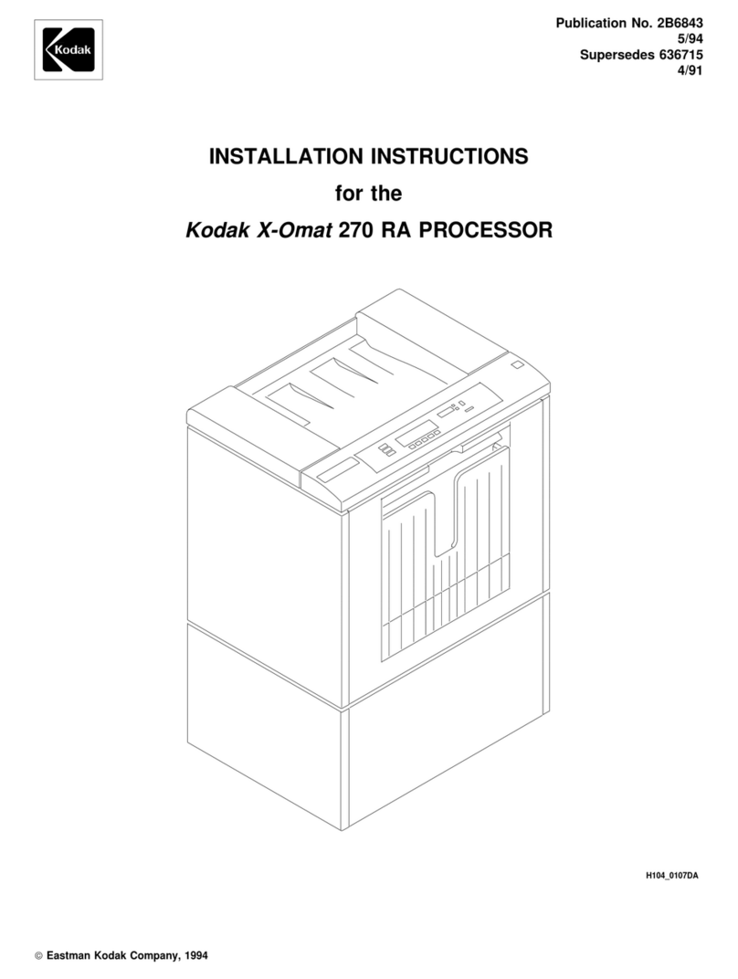
Kodak X-Omat 270 User manual

Publication No. 2B6841
5/94
Supersedes 636716
4/91
OPERATOR MANUAL
for the
Kodak X-Omat
270 RA PROCESSOR
H104_0107DA
Eastman Kodak Company, 1994

PLEASE NOTE
The information contained herein is based on the experience and knowledge relating to the subject matter gained by
Eastman Kodak Company prior to publication.
No patent license is granted by this information.
Eastman Kodak Company reserves the right to change this information without notice, and makes no warranty, express
or implied, with respect to this information. Kodak shall not be liable for any loss or damage, including consequential or
special damages, resulting from the use of this information, even if loss or damage is caused by Kodak’s negligence or
other fault.
To avoid hazardous conditions, keep floors and floor coverings around your KODAK X-OMAT
Processor and associated drains clean and dry at all times. Any accumulation of fluids from
mixing tanks, drain lines, etc, should be cleaned up immediately. In the event of an accumulation
of liquid due to backup, overflow, or other malfunctions of the drain associated with your KODAK
X-OMAT Processor, call a plumber or other contractor to correct any problem with the drain.
Kodak accepts no responsibility or liability whatsoever for the serviceability of any drain connected
to or associated with a KODAK X-OMAT Processor. Such drains are the sole responsibility of the
customer.
2 2B6841

Table of Contents
Description Page
Overview..................................................................................................................................................................4
Product Description ...................................................................................................................................4
Identifying the Covers and Panels and Other Components of the Processor.........................................4
Display Panel.............................................................................................................................................8
Adjusting the Contrast of the Liquid Crystal Display (Display Panel) ......................................................9
Film Processing Cycles...........................................................................................................................10
Replenishment Modes.............................................................................................................................10
Processor Configuration and Setpoints...................................................................................................10
Access Codes..........................................................................................................................................12
Operating Instructions.........................................................................................................................................14
Daily Start-up...........................................................................................................................................14
Dryer Temperature Adjustment...............................................................................................................19
Film-Feeding Procedure ..........................................................................................................................19
Shutdown.................................................................................................................................................21
Processor Setup...................................................................................................................................................22
Configuration............................................................................................................................................22
Replenishment Calibration.......................................................................................................................28
Setpoints..................................................................................................................................................31
Language Option.....................................................................................................................................38
Replenishment Solutions....................................................................................................................................39
Mixing the Developer and Fixer Solutions..............................................................................................39
Draining the Processor Tanks.................................................................................................................39
Filling the Processor Tanks.....................................................................................................................41
Preventive Maintenance ......................................................................................................................................43
Weekly .....................................................................................................................................................43
Problem Solving...................................................................................................................................................46
Menu Flowchart....................................................................................................................................................47
Warranty................................................................................................................................................................49
Publication Change Table...................................................................................................................................50
2B6841 3

Overview
The KODAK X-OMAT 270 RA Processor is a general-purpose radiographic processor,
Product Description which uses a conventional roller transport system to accommodate both roll and sheet
film.
Features of the 270 RA Processor include Microprocessor control, an operator
interface, error detection and indicators, and ‘‘smart’’ replenishment. The 270 RA
Processor also provides 4 operator-selectable film processing cycles, which run at
4 default transport speeds. The 4 cycles are:
• Kwik (K/RA)
• Rapid
• Standard
• Extended
Each cycle has default parameters for transport speed, developer, and fixer
replenishment volumes and for developer, fixer, and dryer temperatures. These
default parameters are stored in memory but can be modified by the operator. A
battery supplies uninterrupted power to the memory so that the parameters do not
have to be reentered each time the Processor is deenergized.
All cycles, except for the K/RA cycle, use standard RP chemicals and film. The K/RA
cycle, however, requires RA chemicals and film.
4 2B6841

Identifying the
Covers and Panels
and Other
Components of the
Processor
H104_0107DA
H104_0107DCE
Panel
Side
Stand
Panel
Side
Non-Drive
Receive Tray
Top Cover
Display
Panel
Exit Panel
Receiving
Bin
Stand
Front
Panel
Figure 1 Receive End of the Processor
2B6841 5

H104_0126DA
H104_0126DCE
Panel
Rear
Stand
Panel
Feed End
Top Cover
Display Panel
Drive
Side
Panel
Stand
Side
Panel
Circuit
Breaker CB1
Figure 2 Feed End of the Processor
6 2B6841

H104_0035DA
H104_0035DCB
Receptacle
Safelight
E: Extended
S: Standard
R: Rapid
K: K/RA
Cycle:
Adjustment
Intensity
Light
Red: Service
Yellow: Wait
Green: Ready
Lights:
Phone Jack
Interface
(RS-232 port)
Connector
Interface
Processor
Circuit Breaker CB1
Figure 3 Circuit Breaker and Safelight
2B6841 7

The operator selects, changes, and monitors processing variables for the KODAK
Display Panel X-OMAT 270 RA Processor, using the Display Panel. See the figure below.
H104_0539BA
Soft Key 4
Soft Key 2
Soft Key 1
H104_0539BCA
Liquid Crystal
Display
Developer Temperature
Display
Backlit
Messages Replenishment
Indicator
Room Light
Sensor
Degree C/F
LED Indicators
Figure 4 Display Panel
The Display Panel provides the following status information of the Processor:
• Ready/Not Ready
• Message/Error
• Current cycle
• Current function for each of the Soft Keys
• Developer Temperature °C or °F Indicator, which provides the current temperature of
the developer in the Processor tank
• Replenishment Indicator, which illuminates when the Replenishment Pumps are
operating
The ‘‘Ready’’ LED on the Display Panel indicates that the Processor is ready to
accept film.
The ‘‘Wait’’ LED indicates that the Processor has not yet reached optimum film
processing conditions. See page 16 for further description of ‘‘Wait’’ events.
The ‘‘Service’’ LED indicates that the Processor has an error that the operator cannot
repair.
NOTE
• See page 48 for the complete Flowchart for the operation of the
display on the Processor.
• The Room Light Sensor disables the Display Panel when the room is dark or
if the Sensor is covered by something such as papers or your hand.
8 2B6841

The Display Panel has 5 keys called ‘‘Soft Keys’’ that the operator uses to select,
change, and monitor Processor variables. These keys are located just below the
Liquid Crystal Display (LCD):
READY/NOT READY CURRENT CYCLE
MESSAGE/ERROR
_______________________________________
SOFT
|
SOFT
|
SOFT
|
SOFT
|
SOFT
KEY
|
KEY
|
KEY
|
KEY
|
KEY
After a key has been used to make a selection from the menus displayed on the LCD,
the functions of the first 4 keys change to describe the next lower level of menu
selections. Keys not used are blank. When pressed, the fifth key, ‘‘DONE/RETURN’’
completes the entry and displays on the LCD the next higher menu level. See page
48 to view the Menu Flowchart for the RA Processor Display Panel. In addition,
procedures contained in this publication show step-by-step the readout of the LCD
after each key selection.
[1] To lighten the display, press and hold Soft Key 4 on the Display Panel. See
Adjusting the Figure 4 on page 8. At the same time, press Soft Key 2 on the Display Panel
Contrast of the to obtain the desired contrast.
Liquid Crystal
Display (Display [2] To darken the display, press and hold Soft Key 4 on the Display Panel. At the
Panel) same time, press Soft Key 1 on the Display Panel to obtain the desired
contrast.
2B6841 9

A Cycle is one of the 4 ways to process film in the Processor. The Extended,
Film Processing Standard, and Rapid cycles are available through the Display Panel. The Kwik (K/RA)
Cycles cycle, which provides the fastest film processing time, requires use of the access code.
See page 12 for more information on the access code.
The Microprocessor automatically adjusts the transport speed, replenishment volumes,
and solution and dryer temperatures to the programmed values for a selected cycle.
Cycle Information for the Processor
Process Time Drop Time Film and Throughput
Cycle in seconds in seconds Chemicals films/hour
RA Film and
Kwik (K/RA) 48 59 268
Chemicals
RA or RP Film,
Rapid 64 79 201
RP Chemicals
RA or RP Film,
Standard 80 98 162
RP Chemicals
RP Film and
Extended 173 213 74
Chemicals
Process Time is the time it takes the leading edge of a sheet of film to travel from the
Detector Rollers to the Exit Rollers of the Dryer Rack.
Drop Time is the time it takes the leading edge of a 35 x 43 cm sheet of film (fed
43 cm wide) to enter the Detector Rollers and the trailing edge to exit the Dryer Rack.
Film/Chemical is the combination of film and chemicals required for optimum image
quality when using the Processor. KODAK
RP
X-OMAT Developer Replenisher and
KODAK
RP
X-OMAT Fixer and Replenisher, or equivalents, may be used with the
Extended, Standard, and Rapid cycles. Only KODAK
RA
X-OMAT Films and
Chemicals may be used for the K/RA cycle. Contact your Kodak representative to
discuss the best option for your needs.
Throughput is the number of 35 x 43 cm sheets of film (fed 43 cm wide) that can be
processed in one hour.
Automatic Replenishment Mode automatically adjusts the replenishment volumes for
Replenishment the developer and fixer according to film usage.
Modes
Flooded Replenishment Mode is for low film usage, less than 25 35 x 43 cm (14 x
17 in.) sheets of film per 8-hour day. Chemicals will be replenished automatically
every 5 minutes or when the equivalent film area of 35 x 43 cm has been processed.
Tank Fill Mode fills empty processing Tanks automatically until the Level Sensor
Probes detect that the Tanks are full.
Disable Replenishment will disable the Replenishment Pumps when you do any
cleaning procedures.
10 2B6841

Setup information consists of the film Processor configuration and process setpoints.
Processor Setup information that was preset at the factory is listed in the table below.
Configuration and
Setpoints
Setup information is stored in battery backed-up RAM (Random Access Memory).
Therefore, you do not need to program new values every time that you turn on the
Processor. Even if power to the Processor is interrupted or the Processor is
turned off, you do not need to program the Processor.
If you wish, you may change the setup information by using the Soft Keys on the
Display Panel; See ‘‘Processor Setup’’ on page 22. The new setup information will be
retained in memory when power is interrupted or turned off.
Processor Default Configuration and Setpoints
Item K/RA RAPID STANDARD EXTENDED
*Replenishment Automatic Automatic Automatic Automatic
Mode
*Temperature Off Off Off Off
Lockout Mode
*Display Units °F, in./min °F, in./min °F, in./min °F, in./min
*Safelight Safelight Safelight Safelight Safelight
Receptacle Mode
*Standby Mode Interval Interval Interval Interval
Developer 35.6°C 37.2°C 34.4°C 34.4°C
Temperature (96°F) (99°F) (94°F) (94°F)
Fixer Temperature 32.2°C35°C 32.2°C 27.7°C
(minimum) (90°F) (95°F) (90°F) (85°F)
(Automatic)
Developer 60 mL 60 mL 60 mL 60 mL
Replenishment
(35 x 43 cm sheet)
(Automatic) Fixer
Replenishment 85 mL 85 mL 85 mL 85 mL
(35 x 43 cm sheet)
193 cm/min 144.8 cm/min 106.7 cm/min 53.3 cm/min
Transport Speed (76 in./min) (57 in./min) (42 in./min) (21 in./min)
48.9°C 48.9°C 48.9°C 48.9°C
Dryer Temperature (120°F) (120°F) (120°F) (120°F)
* Indicated parameters are not selectable on a cycle basis.
2B6841 11

Only service personnel and one primary person should have use of the access
Access Codes codes. The access code 4213 must be entered after the ‘‘GO TO SETUP’’ key on the
main menu is pressed.
This access code is necessary:
• to change setup information preset at the factory and
• to change to or from the ‘‘K/RA’’ cycle
An access code is not necessary:
• to select the Processor cycle (except ‘‘K/RA’’)
• to change the dryer temperature
• to display the current fixer temperature
A second access code 3244 allows the primary operator access to review Processor
status information.
[1] Press the ‘‘GO TO SETUP’’ key on the main menu
READY STD
135 F = DRYER SETPOINT
________________________________________
/\
|
\/
|
SELECT
|
DISPLAY
|
GO TO
DRYER
|
DRYER
|
CYCLE
|
FIX TEMP
|
SETUP
[2] Enter the 4-digit access code 3 2 4 4 .
1
|
2
|
3
|
4
|
CANCEL
||||
REQUEST
[3] Press one of the following:
• ‘‘TOTAL ON TIME’’ key for the total time the Processor has been on
• ‘‘SHEET COUNT’’ key for how many sheets of film have been been
processed
• ‘‘XPORT ON TIME’’ key for the total time the transport system has been on
[4] Press the ‘‘DONE/RETURN’’ key when you are done reviewing the Processor
status information and are ready to return to the previous menu.
TOTAL
|
SHEET
|
XPORT
||
DONE/
ON TIME
|
COUNT
|
ON TIME
||
RETURN
12 2B6841

• Holding down a Soft Key will cause the key to toggle among all its possible options.
Operating For example, holding down the /\ key, will cause the temperature displayed to
Characteristics increase rapidly, as long as the key is held down.
• When the Processor is first turned on, the wash water and Drive Motor run for a
short time and then turn off. The Replenishment Pumps also turn on briefly when
the Processor is turned on.
• If either the developer or fixer solution evaporated while the Processor was off, the
developer and fixer tanks will be automatically replenished to their overflow levels
when the Processor is again turned on.
• When the Film Detector senses film, it turns on the Drive Motor, the water, and the
Dryer.
• To prevent the Replenishment Pumps from pumping replenishment solutions when
film is not being processed, film area is only accumulated by the Film Sensors if the
film enters the Detector Rollers.
• The Drive Motor will not operate if the Top Cover of the Processor is open.
• If the Processor is used in an area that is dark or dimly lit, the Processor’s room light
sensors will detect the lack of bright light and turn off the lights on the display panel
to prevent the fogging of the film which it ‘‘thinks’’ is being processed. The Soft
Keys are also disabled if the Processor is used in an area that is dark or dimly lit.
• On the feed end of the Processor is a panel which indicates the selected film
processing cycle and the correct Processor status. A dimmer (Light Intensity
Adjustment) is provided to adjust the intensity of these indicator lights.
• Fatal errors cause the alarm on the Processor to sound repeatedly until any film in
the Processor exits.
• Non-fatal errors and warnings cause the alarm on the Processor to sound twice
when a film is fed into the Film Detector.
2B6841 13

Operating Instructions
[1] Check that the Racks and Crossovers are in their correct positions.
Daily Start-up
[2] Check that the Water Yoke is in position.
H104_0153BA
H104_0153BCE
Developer
Rack
Wash Rack
Fixer Rack
Water
Yoke
Figure 5 Rack, Crossover, and Water Yoke Positions
[3] Check that the 2 Water Troughs (not shown) are positioned on the bottom of
the Developer/Fixer and Fixer/Wash Crossovers.
[4] Check that the Water Line is connected.
H104_0197BA
H104_0197BCC
Line
Water
Figure 6 Water Line Connection
14 2B6841

[5] Check that developer and fixer solutions are at the overflow levels of each tank.
[6] Install the Evaporation Covers and the Wet Section Cover if they are not
already installed.
[7] Close the Top Cover of the Processor.
H104_0467HA
Cover
Top
Cover (2)
Evaporation Cover
Wet Section
H104_0467HCB
Figure 7 Installing the Wet Section and Evaporation Covers
[8] Turn on the water supply.
NOTE
The incoming water temperature should be between 4° and 29°C (40°
and 85°F).
[9] Remove any film from the Feed Shelf.
[10] Move the wall power switch to the ‘‘ON’’ position.
[11] Move the main Circuit Breaker CB1 to the ‘‘|’’ position.
2B6841 15

IMPORTANT
• You must press the Soft Key for each selection within 20 seconds of
completing the previous entry. If you do not press a key within 20
seconds of the previous entry, the LCD will again display the main
menu. To activate the display, press any Soft Key twice.
• An alarm ‘‘beep’’ will occur twice whenever there is an error condition with the
Processor and a sheet of film is fed into the Processor.
• The Display Panel will be dark and disabled if the room is dark.
[12] To change the film processing cycle, press the ‘‘SELECT CYCLE’’ key.
READY STD
135 F = DRYER SETPOINT
________________________________________
/\
|
\/
|
SELECT
|
DISPLAY
|
GO TO
DRYER
|
DRYER
|
CYCLE
|
FIX TEMP
|
SETUP
[13] Select the desired film processing cycle, if not K/RA:
• ‘‘RAPID CYCLE’’ for the rapid cycle
• ‘‘STD CYCLE’’ for the standard cycle
• ‘‘EXT CYCLE’’ for the extended cycle
RAPID
|
STD
|
EXT
||
DONE/
CYCLE
|
CYCLE
|
CYCLE
||
RETURN
[14] Immediately, press the ‘‘DONE/RETURN’’ key.
RAPID
|
STD
|
EXT
||
DONE/
CYCLE
|
CYCLE
|
CYCLE
||
RETURN
IMPORTANT
• The ‘‘Ready’’ LED indicates that the Processor is ready to accept film.
• The ‘‘Wait’’ LED indicates that the Processor has not yet reached optimum
film processing conditions:
• The ‘‘Service’’ LED indicates that the Processor has an error that the
operator cannot repair.
Cause of ‘‘Wait’’ Condition Error Code Film Accepted
Replenishment Pump E130 Yes
disabled
Developer temperature not ‘‘Temperature Lockout’’ OFF: Yes
E132 or E133
to specification ‘‘Temperature Lockout’’ ON: No
Tanks currently being filled E129 No
Top Cover is not closed E128 No
16 2B6841

[15] When the ‘‘Ready’’ LED comes on, begin processing film.
Located on the feed end of the Processor are 2 rows of status indicator lights. See
Figure 8 on page 18.
(a) The first row contains three colored lights indicating the current status of
the Processor:
• If the Green ‘‘Ready’’ indicator is illuminated, the Processor is ready to
accept film.
• If the Yellow ‘‘Wait’’ indicator is illuminated, the Processor is not yet
ready to accept films.
• If the Red ‘‘Service’’ indicator is illuminated, the Processor is in need
of service.
(b) The second row contains letters indicating the current film processing
cycle:
• If the ‘‘K’’ is illuminated, the Processor is operating in the K/RA cycle.
• If the ‘‘R’’ is illuminated, the Processor is operating in the Rapid cycle.
• If the ‘‘S’’ is illuminated, the Processor is operating in the Standard
cycle.
• If the ‘‘E’’ is illuminated, the Processor is operating in the Extended
cycle.
You may change the brightness of these indicators by turning the Light Intensity
Adjustment located next to the Lights.
2B6841 17

H104_0035DA
H104_0035DCB
Receptacle
Safelight
E: Extended
S: Standard
R: Rapid
K: K/RA
Cycle:
Adjustment
Intensity
Light
Red: Service
Yellow: Wait
Green: Ready
Lights:
Phone Jack
Interface
(RS-232 port)
Connector
Interface
Processor
Circuit Breaker CB1
Figure 8 Circuit Breaker, Safelight Receptacle, and Status Indicator Lights
18 2B6841

[1] Use the main menu to adjust the dryer temperature. You do not need to use
Dryer Temperature the access code. You may select a different dryer temperature for each cycle
Adjustment and store them separately.
IMPORTANT
Always adjust the dryer temperature to the lowest possible
temperature that still allows good drying.
[2] To change the dryer temperature press the:
• /\ key to increase the temperature
• \/ key to decrease the temperature
/\
|
\/
|
SELECT
|
DISPLAY
|
GO TO
DRYER
|
DRYER
|
CYCLE
|
FIX TEMP
|
SETUP
Sheet Film: See Figure 9 on page 20 for the correct film-insertion procedure. Arrows
Film-Feeding indicate the direction in which films are transported into the Processor. Choose either
Procedure the right or the left edge of the Feed Shelf, and always feed films square with that
edge of the Feed Shelf.
• Feed all single-sided films emulsion side up into the Processor,
aligning the film edge with the edge of the Feed Shelf.
• Align films consistently with either the right or left edge of the Feed Shelf.
•Do not pull back films after you feed them into the Processor.
•Do not pull on film as it exits the Processor.
•Do not allow too many sheets of films to accumulate in the receiving bin at
one time.
2B6841 19

H104_9002DC
1 each
35 x 43 cm
or
14 X 17 in.
1 each
35 x 35 cm
or
40 x 40 cm
1 each
33 x 41 cm
30 x 40 cm,
30 x 35 cm,
1 each
24 x 30 cm,
10 x 12 in., or
12.5 x 12.5 in.
1 each
24 x 24 cm
or
9 x 9 in.
1 each
18 x 43 cm
2 each
18 x 43 cm
2 each
18 x 24 cm
or
8 x 10 in.
1 each
18 x 24 cm
or
8 x 10 in.
2 each
6.5 x 8.5 in.
2 each
6.5 x 8.5 in.
3 each
4 x 5 in.,
3.5 x 8 in.,
5 x 7 in.
3 each
10 x 10 cm
or
4 x 4 in.
11 x 14 in.,
or
12 x 15 in.
13 x 18 cm
Figure 9 X-Ray Film Sizes
20 2B6841
Table of contents
Other Kodak Computer Hardware manuals

Kodak
Kodak X-Omat 1000 User manual

Kodak
Kodak RP X-OMAT M6B User manual

Kodak
Kodak MULTILOADER 700 User manual

Kodak
Kodak RP X-OMAT M6B User manual

Kodak
Kodak X-Omat 2000 User manual

Kodak
Kodak Ektalite 1000 User manual

Kodak
Kodak X-Omat 460 RA Processor User manual

Kodak
Kodak X-Omat 270 RA PROCESSOR User manual

Kodak
Kodak RP X-Omat Processor M7B User manual

Kodak
Kodak Prostar User manual