2 TT-1469 6/07
Safety Precautions
Hazardous voltage.
Will cause severe injury or death.
Disconnect all power sources before
opening the enclosure.
DANGER
Instructions
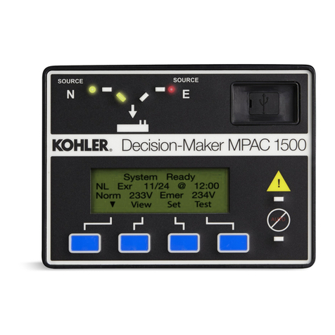
Plug the power cord into a 120 VAC outlet and move the
power switch to the ON position. Refer to transfer switch
Operation/Installation Manual TP-6446, provided, for
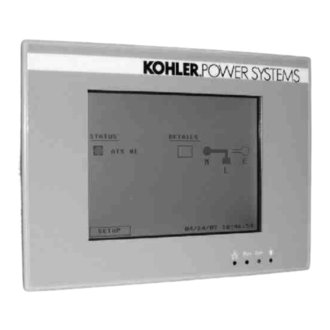
instructions to view and change the transfer switch
controller settings.
Normal Source Failure and Return
The rocker switch simulates normal source available
and normal source failure conditions. With the switch in
the Normal Available position, the controller LEDs
indicate Source N Available and the contactor in the
Source N position.
MovetheswitchtotheNormalFailurepositionto
simulate a loss of the normal source. The controller
sends an engine start signal, indicates Source E
available, and simulates transfer to source E, executing
all applicable time delays during the sequence.
Move the switch back to the Normal Available position to
simulate return of the normal source. The controller
executes the applicable time delays and simulates
transfer back to source N. The engine cooldown time
delay executes if it is not set to zero.
Monitor III Software
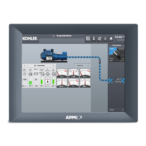
Monitor III software is included with the demonstration
kit. Refer to Monitor III Operation Manual TP-6347,
provided with the demonstration case, for instructions to
load the software onto your PC or laptop computer.
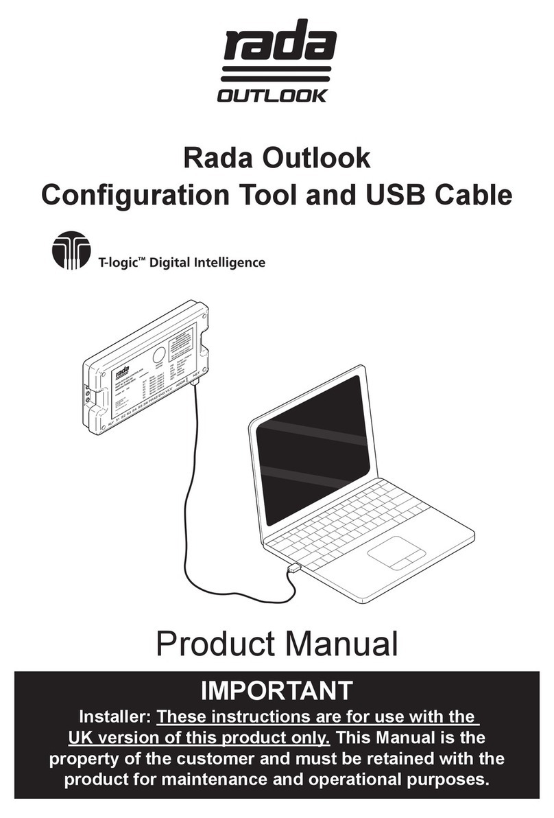
Insert USB interface GM29225 (provided) into the PC’s
USB port to allow operation of the software.
Use a crossover cable to connect the computer to the
demo unit’s ethernet port. Refer to the the Operation
Manuals provided with the demonstration kit to set up
communication between the PC and the ATS controller.
Monitor III software can used to monitor transfer switch
operation and change settings on the controller. Refer
to the Monitor III Operation Manual for usernames,
passwords, and other instructions.
Input/Output Modules
Input/output modules can be connected to the
demonstration unit. Obtain I/O module mounting kit
GM46258-KP1 and one or more I/O modules. Connect
the I/O module cable (included with mounting kit) to the
green 5-pin connector on the demo unit. Refer to
TP-6446 for instructions to set up the I/O Modules.
USB Port
Connect a USB mass storage device (not provided) to
the USB port to save settings or download files. See
TP-6446 for instructions.
Fuse
The demonstration unit has a 5-amp, slow-blow IEC
ceramic 5x20 fuse. Obtain replacement fuses locally if
required.
Parts List
MPACt1500 Demonstration Case
Kit: GM51765-KP1
Qty. Description Part Number
1 USB Interface (Monitor III key) GM29225
1Monitor III Software GM41097
1Assembly, MPAC Demo Unit GM51765
1Power cord GM55383
1O/M Monitor III TP-6347
1O/I/M Model KCS/KCP TP-6446

