manuals.online logo
Brands
  1. Home
  2. •
  3. Brands
  4. •
  5. Kohler
  6. •
  7. Controllers
  8. •
  9. Kohler Decision-Maker 3500 User manual

Kohler Decision-Maker 3500 User manual

TT-1638 11/14
INSTALLATION INSTRUCTIONS
Original Issue Date: 11/14
Model: 33--150 kW Generator Sets
Market: Marine
Subject: Decision-Makerr3500 Controller Service Replacement Kit GM92086
Introduction
The controller service replacement kit is available to
replace a non-functional controller. Use the following
procedure to install the replacement controller. See
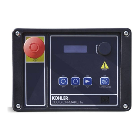
Figure 1 for controller identification. For features and
operation of the controller, see the operation manual
(TP-6861).
1. Mini USB connection
1
Figure 1 Decision-Makerr3500 Controller
Note: Do not use this controller replacement installation
instruction for upgrading software.
When replacing the controller, the following data must
be resident for the controller to function. Controller
service replacement kits do not include the three files
installed at the factory. The service technician must
install the following three files into the replacement
controller.
DApplication program contains the software that
controls system operation. The application file was
preprogrammed in the original controller at the
factory.
DPersonality profile is specific to the engine and
alternator and was preprogrammed in the original
controller at the factory.
A backup disk of the personality profile and
application program is supplied with the literature
packet shipped with the generator set. Typically, the
distributor stores this disk for possible future use such
as controller replacement or other circumstances
requiring a backup.
Note: If the personality disk is NOT available, request
a replacement from Kohler Co. using the
generator set serial number or order number.
DUser parameters unique to an installation include
timer values, setpoints, generator set data such as
voltage and input/output selections. These
parameters are typically set up for or by the installer at
the time of installation. User parameters are typically
recorded on the personality profile disk, a separate
backup disk/drive, or written on a paper form.
Note: If the user parameters are included on the
personality disk, the disk label should indicate
Site Program—Yes.
Read the entire installation procedure. Perform the
steps in the order shown.
Always observe applicable local and national electrical
codes.
Note: The following service kit procedure changes only
the controller. If the generator set requires
voltage reconnection and/or frequency
adjustment, see the installation manual
(TP-6862).
2TT-1638 11/14
Installation Requirements
The following items are necessary PC requirements for
installing the controller service replacement kits.
DSiteTechtSoftware Version 3.6 or higher from the
Kohler Power Resource Center website using the
TechTools button to download on your PC hard drive
or disk if not already installed on your PC.
DTP-6701 SiteTechtSoftware Operation Manual
available from the Kohler Power Resource Center
website using the TechTools button.
DUSB Cable with male USB-A and mini-B connectors.
See TP-6701.
Safety Precautions
Observe the following safety precautions while installing
the kit.
Accidental starting.
Can cause severe injury or death.
Disconnect the battery cables before
working on the generator set.
Remove the negative (--) lead first
when disconnecting the battery.
Reconnect the negative (--) lead last
when reconnecting the battery.
WARNING
Disabling the generator set. Accidental starting can
cause severe injury or death. Before working on the
generator set or equipment connected to the set, disable the
generator set as follows: (1) Press the generator set off/reset
button to shut down the generator set. (2) Disconnect the
power to the battery charger, if equipped. (3) Remove the
battery cables, negative (--) lead first. Reconnect the negative
(--) lead last when reconnecting the battery. Follow these
precautions to prevent the starting of the generator set by the
remote start/stop switch.
Hazardous voltage.
Can cause severe injury or death.
Operate the generator set only when
all guards and electrical enclosures
areinplace.
Moving parts.
WARNING
Grounding electrical equipment. Hazardous voltage can
cause severe injury or death. Electrocution is possible
whenever electricity is present. Ensure you comply with all
applicable codes and standards. Electrically ground the
generator set and related equipment and electrical circuits.
Turn off the main circuit breakers of all power sources before
servicing the equipment. Never contact electrical leads or
appliances when standing in water or on wet ground because
these conditions increase the risk of electrocution.
Connecting the battery and the battery charger.
Hazardous voltage can cause severe injury or death.
Reconnect the battery correctly, positive to positive and
negative to negative, to avoid electrical shock and damage to
the battery charger and battery(ies). Have a qualified
electrician install the battery(ies).
Short circuits. Hazardous voltage/current can cause
severe injury or death. Short circuits can cause bodily injury
and/or equipment damage.Do not contact electrical
connections with tools or jewelry while making adjustments or
repairs. Remove all jewelry before servicing the equipment.
Installation Procedure
1. Acquire the user parameters.
1.1 Choose one of the following methods to retrieve
the user parameters:
DBackup disk/file. If a backup disk/file was
previously made, obtain the parameters
from this disk/file. If a disk/file was not
previously made, create a backup if possible
using the SiteTechtsoftware. The existing
controller must function in order to create
the file.
DPaper form. Parameters may have been
previously recorded on a User-Defined
Settings form or other similar form. If the
parameters have not been saved to a
backup disk/file, and if SiteTechtis not
available, record the pertinent parameter
values for manual entry (below) into the
replacement controller.
DController menu. Manually review the
controller menu displays if possible and
enter the parameter information in the
Decision-Makerr3500 Operation Manual
TP-6861.
1.2 Save the user parameter data for step 6.3.
2. Remove the generator set from service.
2.1 Press the generator set master control
OFF/RESET button.
2.2 Disconnect the power to the battery charger, if
equipped.
TT-1638 11/14 3
2.3 Disconnect the generator set engine starting
battery(ies), negative (--) lead first.
2.4 Disconnect the generator set from load by
opening the line circuit breaker.
3. Remove the existing controller and
disconnect the electrical connections.
3.1 Remove the junction box panels as needed to
access the wiring.
3.2 Remove the four controller panel screws.
Note: Clearly mark all disconnected leads from
the controller with tape to simplify
reconnection.
3.3 Disconnect the controller harness connectors:
DP1 (35-Pin) Connector for
engine/generator wiring harness.
DP2 (14-Pin) Connector for sensor input
connections and relay driver output
connections.
DP3 (8-Pin) Connector for generator set
output voltage sensing and paralleling bus
voltage sensing connections.
DP4 (Ethernet) Connector connects to a
network communication line.
Note: These connections are typical and may
not apply to all applications. See the
corresponding wiring diagram found in
the operation manual (TP-6861).
1. P1 (35-pin) connector
2. P2 (14-pin) connector
3. P3 (8-pin) connector
4. P4 Ethernet connector
GM86969A
123
4
Figure 2 Controller Harness Connectors
4. Reconnect the electrical connections
and install the replacement controller.
4.1 Reconnect all of the electrical connections
disconnected in step 3.3.
4.2 Align the controller panel with the mounting
holes and install four screws.
4.3 Replace the junction box panels if previously
removed.
5. Restore power to the generator set.
5.1 Reconnect the generator set engine starting
battery, negative (--) lead last.
5.2 Reconnect power to the battery charger, if
equipped.
6. Set the device profile.
6.1 Connect the PC to the Decision-Makerr3500
controller using a USB cable. See Figure 1 for
the location of the USB connection port.
6.2 Insert the personality profile backup disk/drive
and load the data. Refer to Tech Tools—
Software and TP-6701 SiteTechtSoftware
Operation Manual for details.
6.3 Choose one of the following methods to load the
user parameters.
DBackup disk/drive. Use a PC with
SiteTechtsoftware to load the data from
the user parameter backup disk/drive.
DPaper form. Use a PC with SiteTechtto
enter the user parameter data from a
filled-out form.
6.4 If any changes are made using SiteTecht,
create a new user parameter data backup
disk/drive. Refer to TP-6701 SiteTecht
Software Operation Manual for details.
6.5 Disconnect the USB cable.
6.6 Power down the unit by using the prime power
switch (if equipped) or by disconnecting the
battery negative (--) terminal.
6.7 Wait at least 15 seconds and then power up the
unit by using the prime power switch (if
equipped) or by reconnecting the battery
negative (--) terminal.
6.8 Refer to the Decision-Makerr3500 Operation
Manual (TP-6861). Calibrate the generator set
as instructed in the Calibration submenu.
4TT-1638 11/14
6.9 Press the RUN button to start the generator set.
6.10 Test the functionality of the controller by
reviewing the menus and observing the system
status lamps. Use the Operation Manual as
needed.
6.11 Press the OFF button to stop the generator set
after completing the test.
6.12 Reconnect the generator set to load by closing
the line circuit breaker.
6.13 Press the generator set master control AUTO
button for startup by remote transfer switch or
remote start/stop switch.
Parts List
Controller Service Replacement Kit
Kit: GM92086
Qty. Description Part Number
1Controller assembly GM86809-1
KOHLER CO., Kohler, Wisconsin 53044 USA
Phone 920-457-4441, Fax 920-459-1646
For the nearest sales and service outlet in the
US and Canada, phone 1-800-544-2444
KOHLERPower.com
Kohler Power Systems
Asia Pacific Headquarters
7 Jurong Pier Road
Singapore 619159
Phone (65) 6264-6422, Fax (65) 6264-6455
Availability is subject to change without notice. Kohler Co. reserves the
right to change the design or specifications without notice and without any
obligation or liability whatsoever. Contact your local Kohlerrgenerator
set distributor for availability.
2014 by Kohler Co. All rights reserved.

Other Kohler Controllers manuals

Kohler GM17071-KP1 User manual

Kohler

Kohler GM17071-KP1 User manual

Kohler Modbus MPAC 1000 Instruction Manual

Kohler

Kohler Modbus MPAC 1000 Instruction Manual

Kohler rada outlook User manual

Kohler

Kohler rada outlook User manual

Kohler Decision-Maker 3000 Instruction Manual

Kohler

Kohler Decision-Maker 3000 Instruction Manual

Kohler APM303 User manual

Kohler

Kohler APM303 User manual

Kohler 14RES User manual

Kohler

Kohler 14RES User manual

Kohler APM802 User manual

Kohler

Kohler APM802 User manual

Kohler Decision-Makerr MPAC 1500 User manual

Kohler

Kohler Decision-Makerr MPAC 1500 User manual

Kohler Dongle 23777T User manual

Kohler

Kohler Dongle 23777T User manual

Kohler APM402 Instruction Manual

Kohler

Kohler APM402 Instruction Manual

Kohler K-99695 Assembly instructions

Kohler

Kohler K-99695 Assembly instructions

Kohler K-9384 Assembly instructions

Kohler

Kohler K-9384 Assembly instructions

Kohler Power Systems GM49279-KP1 User manual

Kohler

Kohler Power Systems GM49279-KP1 User manual

Kohler Decision-Makerr MPAC 1500 User manual

Kohler

Kohler Decision-Makerr MPAC 1500 User manual

Kohler GM35950 Use and care manual

Kohler

Kohler GM35950 Use and care manual

Kohler K-7124 Assembly instructions

Kohler

Kohler K-7124 Assembly instructions

Kohler Curtis F Series User manual

Kohler

Kohler Curtis F Series User manual

Kohler 6EKOD User manual

Kohler

Kohler 6EKOD User manual

Kohler K-1663 User manual

Kohler

Kohler K-1663 User manual

Kohler 8.5RES User manual

Kohler

Kohler 8.5RES User manual

Kohler K-1647 Assembly instructions

Kohler

Kohler K-1647 Assembly instructions

Kohler K-1647 User manual

Kohler

Kohler K-1647 User manual

Popular Controllers manuals by other brands

YOKOGAWA TC 10-L Engineering manual

YOKOGAWA

YOKOGAWA TC 10-L Engineering manual

Festo CMMP Series Description

Festo

Festo CMMP Series Description

Mitsubishi Q Series Programming guide

Mitsubishi

Mitsubishi Q Series Programming guide

Digital Monitoring Products X1 quick start guide

Digital Monitoring Products

Digital Monitoring Products X1 quick start guide

Wessex VMOP 3045M Technical bulletin

Wessex

Wessex VMOP 3045M Technical bulletin

sisel ENDA ERFA1-NTC-240 Series quick start guide

sisel

sisel ENDA ERFA1-NTC-240 Series quick start guide

Viega Fonterra Smart Control Instructions for use

Viega

Viega Fonterra Smart Control Instructions for use

Sices GC315 user manual

Sices

Sices GC315 user manual

MPPT SR4810 user manual

MPPT

MPPT SR4810 user manual

gefran GRM-H 15 CONFIGURATION AND PROGRAMMING MANUAL

gefran

gefran GRM-H 15 CONFIGURATION AND PROGRAMMING MANUAL

Linear Technology LT3790 Demo Manual

Linear Technology

Linear Technology LT3790 Demo Manual

Omron CJ - PROGRAMMING  12-2009 Programming manual

Omron

Omron CJ - PROGRAMMING 12-2009 Programming manual

Omron E5 K-T - datasheet

Omron

Omron E5 K-T - datasheet

White Rodgers UNIVERSAL INTEGRATED FURANCE CONTROL... installation instructions

White Rodgers

White Rodgers UNIVERSAL INTEGRATED FURANCE CONTROL... installation instructions

Digifort DGF-KB1000 User Manual and Technical References

Digifort

Digifort DGF-KB1000 User Manual and Technical References

Sherline Products MASSO quick start guide

Sherline Products

Sherline Products MASSO quick start guide

motortronics VMX Series Basic Installation and Quick Startup Guide

motortronics

motortronics VMX Series Basic Installation and Quick Startup Guide

Cirrus Logic Crystal LAN CS8900A Reference manual

Cirrus Logic

Cirrus Logic Crystal LAN CS8900A Reference manual

manuals.online logo
manuals.online logoBrands
  • About & Mission
  • Contact us
  • Privacy Policy
  • Terms and Conditions

Copyright 2025 Manuals.Online. All Rights Reserved.