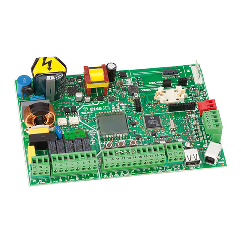
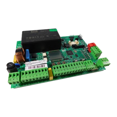
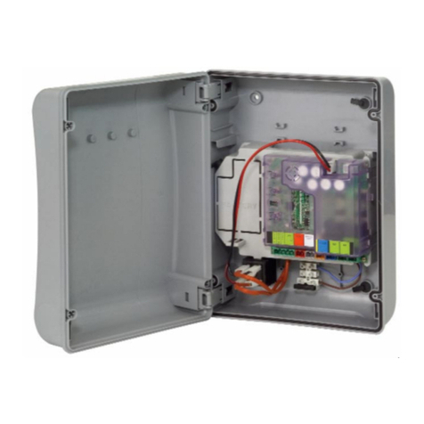
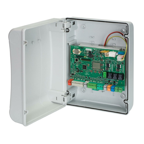
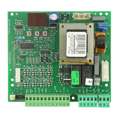
FAAC E024 U User manual

FAAC International Inc.
Headquarter & East Coast Operations
3160 Murrell Rd
Rockledge, FL 32955
Tel. 800 221 8278
www.faacusa.com
West Coast Operations
357 South Acacia Avenue
Unit 357
Fullerton, CA 92831
E024U Solar Kit

2
This solar kit allows to use the E024U control board with the
power. generated by a solar panel. Thanks to the high per-
formance built in solar charger/controller the battery can be
charged quickly and reliably while the low power idle mode on
the E024U allows for smooth operation
Due to the different power requirements of different operator
types we have two versions of this kit:
3352.1 Kit for Electromagnetic operators
3353.1 Kit for Hydraulic operators
1 2 3 4
567
1. Connections Terminal Block
2. Solar Controller
3. Circuit Breaker
4. Activation Push Button
5. Accessories DIN Rail
6. E024U Control Board
7. Battery
1. DESCRIPTION AND CHARACTERISTICS 2. TECHNICAL SPECIFICATIONS
3. CHARGER / CONTROLLER FEATURES
Solar Kit
Fig. 1
+–
BATTERYSOLAR LOAD
+–+–
{
Remove
Jumper
Wire for
Flooded
Battery
SEALED
OR
FLOODED
SELECT
24
V
4 3 2 1 6 5
SOLAR CONTROLLER SS-10L
NominalRating
24 Volts dc
SolarIn 10A
Load 10A
See Operator’s
Manual
E11220 4
UL 1604
CSA2 2.2 No. 213-M198 7
Cl I, Div 2,
GP ABCD
Haz. Loc.
Voc =13.5Vdc
BATTERYSTATUS
SETTING
+
J24
CHARGINGSTATUS
3352.1 3353.1
Nominal system voltage 24 Vdc
Solar panel power 30 W
Max. solar input voltage 60 Vdc
Max Solar current 10A 20A
Battery nominal voltage 24Vdc
Maximum Load Current 10A 20A
Operating ambient temperature
-4°F +131°F
Protections short circuit, over-current,reverse
polarity, high temperature, high
voltage
SEALED
OR
FLOODED
SELECT
LOAD
BATTERY
SOLAR Remove
Jumper
Wire for
Flooded
Battery
{
12 V
BATTERY STATUSTEMP. SENSORCHARGING STATUS
!
See Operator’s
Manual
Nominal Rating
12 Volts dc
Max. Input30 V
Solar 6.5 A
Battery 6.5 A
Load 10.0 A indooruse only
Use Copper
Conductors Only
CONFORMS TO UL STD 1604
CERTIFIED TO CAN/CSA STD
C22.2 NO.213-M1987
Class 1Division 2
GroupsA,B,C,D
HazardousLoc.
For theRisk ofExplosion Only
Operating Temp. Code: T5
MORNINGSTAR
S S
6
UN AVER-
SOLAR CONT ROLLER SS-6-1 2V
1
2
54
3
1. Status LED
An LED indicator that shows charging status and also
indicates when a solar input fault condition exists.
2. Power Terminal Block
Power terminations for system Solar, Battery, and Load
connections.
3. Battery Select Jumper
A removable jumper to select the battery type.
4. Local Temperature Sensor
Measures ambient temperature. Battery regulation is ad-
justed based on ambient temperature changes.
5. Battery Status LEDs
Provides approximate battery state of charge indication
and also indicates when a system or load fault condition
exists.
Fig. 2

3
As soon as the batteries are connected the solar control-
ler will start a self checking procedure, the battery status
LED will blink in sequence and stop at the corresponding
charge level
Plug the solar panel to the cables that go to the terminal
block:
Connect the supplied cable with MC4 connectors to the
solar panel terminal block, make sure to follow the draw-
ing below for the proper polarity
Connect Earth Ground to the negative pole of the solar
panel
Connect the battery to the corresponding terminal block.
with the suppled cable. Make sure to folow the polarity
SOLAR PANEL
+-+ -
BATTERY
+ +- -
12V 12V
If the solar panel has enough exposure to light the green
Status LED will be ON
Turn the Control Board power ON using the circuit
breaker. If the battery voltage is below 26V the board will
turn on right away, if the battery voltage is above 26V the
board will go through a batch of internal testing before
turning on. The tests will last about 40 sec.
NOTE:
The Charger / Controller is supplied by default for use
with sealed batteries. If ooded batteries are used remove
jumper (3)
4. WIRING
Solar Kit
Fig. 3
Fig. 4

4
Solar Kit
BATTERY STATUS LEDS
The Battery Status LEDs (Fig. 2 ref. (5) ) indicate the level
of charge on the battery. The indication is based only on bat-
tery voltage setpoints, which provides an approximation of
the actual state of charge of the battery.
Battery Status LED indications.
LED Indication Battery Sta-
tus
Load-
Status
Green Flashing Charging ON
Green Slow Flashing Trickle Charge ON
Green On solid Battery Full ON
Yellow On solid Battery Half
Full
ON
Red Flashing Battery Low ON
Red On solid Battery Empty OFF
None No LEDS On No Battery OFF
Status LED (Fig 2 Ref (1) ) Error Indications
• Solar overload Flashing Red
• High Voltage Disconnect Flashing Red
• High Temperature Disconect Flashing Red
• Internal Damage Solid Red1
Battery Status LEDs (Fig 2 Ref (5) ) Error Indications
• High Voltage Disconnect R - G Sequencing
• High Temperature Disconnect R - Y Sequencing
• Load Overload R&G - Y Sequencing
• Self-test Error R - Y - G Sequencing
STATUS LED
The Status LED (Fig. 2 ref. (1) ) indicates charging status
and any existing solar input error conditions. The Status LED
is on when charging during the day and off at night. The Sta-
tus LED will ash red whenever an error condition(s) exists.
Status LED indications.
Color Indication Operating State
None Off (with heart-
beat¹)
Night
Green On Solid (with
heartbeat²)
Charging
Red Flashing Error
Red On Solid Critical Error
¹ Status LED heartbeat indication ickers ON briey every
5 seconds
² Status LED heartbeat indication ickers OFF briey every
5 seconds
5. SOLAR CONTROLLER LED INDICATION
6. TROUBLESHOOTING
Note:
A solid red Status LED indicates that a critical fault has
been detected. Critical faults typically indicate that the
controller is damaged and requires service.
LED error indications can be interpreted as follows:
“R - G sequencing” means that the Red LED is on, then
the Green LED is on, then Red LED is on....
“R&G - Y sequencing” means that both the Red LED and
Green LED are on, then just the Yellow LED is on, then
Red and Green LED are on....
Solar Overload
If the solar current exceeds the maximum solar rating, the
controller will stop charging until the solar current returns
to within its operational rating.
High Voltage Disconnect
The battery voltage has exceeded the controller’s maxi-
mum regulation limit of 30.6V . The solar and load will be
disconnected until the battery voltage decreases to the
reconnect threshold of 28V.
High Temperature Disconnect
The heatsink temperature has exceeded 185 °F (85 °C)
and the solar and load is disconnected. The controller will
automatically reconnect when the heatsink cools to 176 °F
(80 °C).
Load Overcurrent
If the load current exceeds the maximum load current rat-
ing, the controller will disconnect the load.
The controller will attempt to reconnect the load two (2)
times approximately 10 seconds apart. If the overcurrent
condition remains after the rst two (2) attempts, the fault
must be cleared by removing and reapplying power.
This error can also indicate a reverse polarity on the bat-
tery. Check wiring.

5
Solar Kit
+–
BATTERYSOLAR LOAD
+–+–
{
Remove
Jumper
Wir e for
Flooded
Battery
SEALED
OR
FLOODED
SELECT
24
V
4 3 2 1 6 5
SOLAR CONTROLLER SS-10L
NominalRating
24 Volts dc
Solar In 10A
Load 10A
See Operator’s
Manual
E1 1220 4
UL 1604
CSA2 2.2 No. 213-M198 7
Cl I, Div 2,
GP ABCD
Haz. Loc.
Voc =13.5Vdc
BATTERY STATUS
CHARGING STATUS
SETTING
+
J24
SOLAR PANEL
+-
BATTERY
+-

3160 Murrell Rd
Rockledge, FL 32955
www.faacusa.com
legal responsibility to effect such replacement, to make such
repair, or otherwise. This limited warranty extends only to
wholesale customers who buy directly through FAAC Inter-
national, Inc.’s normal distribution channels. FAAC Interna-
tional, Inc., does not warrant its products to end consumers.
Consumers must inquire from their selling dealer as to the
nature and extent of that dealer’s warranty, if any. This war-
ranty is expressly in lieu of all other warranties expressed
or implied including the warranties of merchantability and
tness for use. This warranty shall not apply to products
or any part thereof which have been subject to accident,
negligence, alteration, abuse, or misuse or if damage was
due to improper installation or use of improper power source,
or if damage was caused by re, ood, lightning, electrical
power surge, explosion, wind storm, hail, aircraft or vehicles,
vandalism, riot or civil commotion, or acts of God.
To the original purchaser only:
FAAC International, Inc., warrants, for twenty-four (24)
months from the date of invoice, the gate operator systems
and other related systems and equipment manufactured by
FAAC S.p.A. and distributed by FAAC International, Inc.,
to be free from defects in material and workmanship under
normal use and service for which it was intended provided it
has been properly installed and operated.
FAAC International, Inc.’s obligations under this warranty
shall be limited to the repair or exchange of any part of parts
manufactured by FAAC S.p.A. and distributed by FAAC Inter-
national, Inc. Defective products must be returned to FAAC
International, Inc., freight prepaid by purchaser, within the
warranty period. Items returned will be repaired or replaced,
at FAAC International, Inc.’s option, upon an examination of
the product by FAAC International, Inc., which discloses, to
the satisfaction of FAAC International, Inc., that the item is
defective. FAAC International, Inc. will return the warranted
item freight prepaid. The products manufactured by FAAC
S.p.A. and distributed by FAAC International, Inc., are not
warranted to meet the specic requirements, if any, of safety
codes of any particular state, municipality, or other jurisdic-
tion, and neither FAAC S.p.A. or FAAC International, Inc.,
assume any risk or liability whatsoever resulting from the
use thereof, whether used singly or in combination with other
machines or apparatus.
Any products and parts not manufactured by FAAC S.p.A.
and distributed by FAAC International, Inc., will carry only
the warranty, if any, of the manufacturer. This warranty shall
not apply to any products or parts thereof which have been
repaired or altered, without FAAC International, Inc.’s written
consent, outside of FAAC International, Inc.’s workshop, or
altered in any way so as, in the judgment of FAAC Interna-
tional, Inc., to affect adversely the stability or reliability of
the product(s) or has been subject to misuse, negligence, or
accident, or has not been operated in accordance with FAAC
International, Inc.’s or FAAC S.p.A.’s instructions or has been
operated under conditions more severe than, or otherwise
exceeding, those set forth in the specications for such
product(s). Neither FAAC S.p.A. nor FAAC International, Inc.,
shall be liable for any loss or damage whatsoever result-
ing, directly or indirectly, from the use or loss of use of the
product(s). Without limiting the foregoing, this exclusion from
liability embraces a purchaser’s expenses for downtime or
for making up downtime, damages for which the purchaser
may be liable to other persons, damages to property, and
injury to or death of any persons.
FAAC S.p.A. or FAAC International, Inc., neither assumes
nor authorizes any person to assume for them any other
liability in connection with the sale or use of the products of
FAAC S.p.A. or FAAC International, Inc. The warranty herein
above set forth shall not be deemed to cover maintenance
parts, including, but not limited to, hydraulic oil, lters, or the
like. No agreement to replace or repair shall constitute an
admission by FAAC S.p.A. or FAAC International, Inc., of any
LIMITED WARRANTY
Other manuals for E024 U
3
This manual suits for next models
2
Table of contents
Other FAAC Controllers manuals