KOKE HTR-2020 User manual

1

2
K
KOKE INC
HTR2020 & HTR2020C
SERIAL NUMBER:
OPTIONS:

3
Table of Contents
SAFETY INFORMATION
WARNING ..................................................................................................................................4
INSTALLATION...........................................................................................................................4
MAINTENANCE & TROUBLESHOOTING..................................................................................4
OPERATION................................................................................................................................4
INSTALLATION
INSTALL PROCEEDURE............................................................................................................5
INSTALLATION LAYOUT DIAGRAM...........................................................................................7
HYDRAULIC LAYOUT ................................................................................................................8
INTERIOR/EXTERIOR LIGHTS..................................................................................................9
OPERATING INSTRUCTIONS
FOR HYDRAULIC DOCK LEVELER.........................................................................................10
FOR MECHANICAL DOCK LEVELER.......................................................................................10
ADDITIONAL SITUATIONS.......................................................................................................11
OVERRIDE MODE ...................................................................................................................12
TROUBLE SHOOTING
RESTRAINT WILL NOT RISE..................................................................................................13
RESTRAINT ARM DRIFTS......................................................................................................13
RESTRAINT WILL NOT LOWER..............................................................................................13
MANUAL LOWER VALVE..........................................................................................................13
DIAGRAMS & PART LISTS
HYDRAULIC LAYOUT..................................................................................................................8
PROXIMITY SWITCH...............................................................................................................14
TRUCK RESTRAINT ASSEMBLY.............................................................................................15
ELECTRICAL SCHEMATIC.......................................................................................................16
GENERAL MAINTENANCE SCHEDULE............................................................................................17
WARRANTY INFORMATION..............................................................................................................18

4
SAFETY INFORMATION
WARNING: Failure to read and understand the entire contents of this manual
may result in damage to the equipment, bodily injury and/or death.
DURING INSTALLATION:
1.Personnelinstallingthisequipmentmustbequaliedandexperiencedinsafe
working procedures.
2. All lifting and slinging devices must be in proper working condition and used in
the proper manner.
3.Allelectricaltobedonemustbeperformedbyaqualiedelectricianandmust
meet all applicable local codes.
4.Concretemustbeinexcellentconditionwithnocracksinthemountingface
within 4 ft. of the truck restraint and dock leveler.
5. DO NOT install the truck restraint on brick, concrete block or similar surfaces.
WHILE PERFORMING MAINTENANCE & TROUBLE SHOOTING:
1. Perforn proper lock out/tag out of the power supply.
2. Barricade in front of the dock leveler on the loading dock area and in the
driveway.
3. When replacing parts, use only genuine Koke Inc. parts.
DURING OPERATION:
1. Keep clear of the equipment’s operating path.
2. DO NOT operate with anyone standing in front of the lip of the dock leveler.
3. DO NOT wear loose clothing or jewelry while operating this equipment.
4. Keep hands, limbs and loose hair clear of the equipment during positioning or
storing of the dock leveler and truck restraint.
5. DO NOT attempt to “ride” on the equipment during the positioning or storing of
the dock leveler or truck restraint.
6. DO NOT use the truck restraint or dock leveler if you believe it is in an unsafe
condition due to damaged understructure, broken welds, oil leaks, etc.

5
INSTALLATION PROCEDURES
STEP 1 MATERIAL INSPECTION:
1. Open and inspect all of the materials received.
2. Immediately report any damage or material shortages to Koke Inc.
3. Study all installation instructions and drawings.
4. Determine the proper locations for the signs, controls, truck restraint and
exteriorlightingsystem.
STEP 2 INSTALLATION OF THE TRUCK RESTRAINT:
1.Placerestraintboxinthecenterofthedooropening.
2. Mark the nine (9) hole positions on the face of the foundation wall.
3.Drillnine(9)5/8”diameterholesapproximately6”deep.
4.Bolttherestraintboxtofoundationwallusing5/8”x5”Lanchorbolts
STEP 3 HYDRAULIC CONNECTION TO LEVELER & TRUCK RESTRAINT:
See connection diagram (pg. 7 & 8) for hose routing.
Important notes:
1. Hydraulic system must be clear of debris / dirt particles and all hoses capped/
covered when feeding through the conduit.
2. Drain oil and clean reservoir.
3. Flush hydraulic system.
4.Rellreservoirwithnewoil.
Failure to do items 1-4 above will cause damage to the unit and void the
warranty.
5.Requiredhydraulicoil:MOBILDTE10Excel15orequivalent.
STEP 4 MOUNTING:
1.Selectlocationandmounttheexteriorsignandlightsystemasshownonpg.7.
2.Selectlocationandmounttheinteriorcontrolboxandsignasshownonpg.7.
STEP 5 ELECTRIC PROXIMITY SWITCH INSTALLATION TO EXISTING UNIT:
1. Mount the limit switch plate behind the leveler lip.(See diag. on pg 14)
2. The switch plate can be either welded or bolted into place.(See diag. on pg.14)
STEP 6 ADJUST THE PROXIMITY SWITCH LIMIT ON EXISTING UNIT:
(Seepage14forProximitySwitchdiagram)
1. Adjust the limit switch within 3/16” of the lip.
(NOTE: lip must be tight against its stop (fully retracted position))

6
STEP 7 ELECTRICAL INSTALLATION:
1.Completeallnecessarywiringfromcontrolboxto:
(See Electrical Schematic pg. 16)
A.Exteriorlight.
B.Junctionboxlocatedatthetruckrestraint.
C.Electricalproximityswitchbehindlevelerlip(seepg.14)
D. Hydraulic power pack.
STEP 8 FINAL SET-UP ADJUSTMENTS:
1.Makesuretheexteriorlightsdonotchangebacktogreenuntiltherestraint
is completely closed in its stored postioin.
2. To increase or decrease the time, adjust the electrical timer on the circuit
board inside the control
box.
NOTES:
* Hydraulic system must be completely clear of dirt particles and all hoses must
be covered when passing through conduits.
*Whenconnectingtoanexistingdockleveler,ushandcleanthehydraulicsystem
including the reservoir and add new oil.
Failure to complete these 2 items will VOID THE WARRANTY.

7
INSTALLATION LAYOUT DRAWING
$
'(7$,/$
6&$/(
+75
02817&(17(5('
IN DOOR OPENING
(/(&75,&$/&211(&7,216)520&,5&8,7%5'
62/,12,'
'5,)7/,0,76:,7&+
352;6:,7&+
+<'5$8/,&+26(7&211(&7,21
720$,1/,)7&</,1'(5
,7(0
(;7(5,25
6723*2/,*+7:,7+
6,*1
,7(0
02817+,*+
)520'5,9(:$<
(/(&75,&$/)(('
72352;,0,7<6:ITCH
;
$1&+25%2/76
352;,0,7<%5$&.(76:,7&+
,7(0
,17(5,25&21752/3$1(/
02817+,*+)520%27720
2)3$1(/72)/225
6,=(
':*12
$
5(9
5(9'$7(
.2.(,1&
35235,(7$5<$1'&21),'(17,$/
7+(,1)250$7,21&217$,1(',17+,6'5$:,1*,67+(62/(3523(57<
2)
.2.(,1&
$1<5(352'8&7,21,13$5725$6$:+2/(:,7+287
7+(:5,77(13(50,66,212)
.2.(,1&
,6352+,%,7('
'$7(
':*%<
0$7(5,$/

8
TYPICAL HYDRAULIC DIAGRAM FOR TRUCK
RESTRAINT with KOKE DOCK LEVELER

9
INTERIOR LIGHTS / CONTROL PANEL / SIGN
Control panel operates truck restraint and electric/hydraulic dock leveler.
Control panel also has light communication system for dock attendant and/or forklift
operator.
EXTERIOR LIGHTS / SIGN
Exteriorlightcommunicationsystemfortruckdriver.

10
OPERATING INSTRUCTIONS
Read and understand the safety information (See pg. 4).
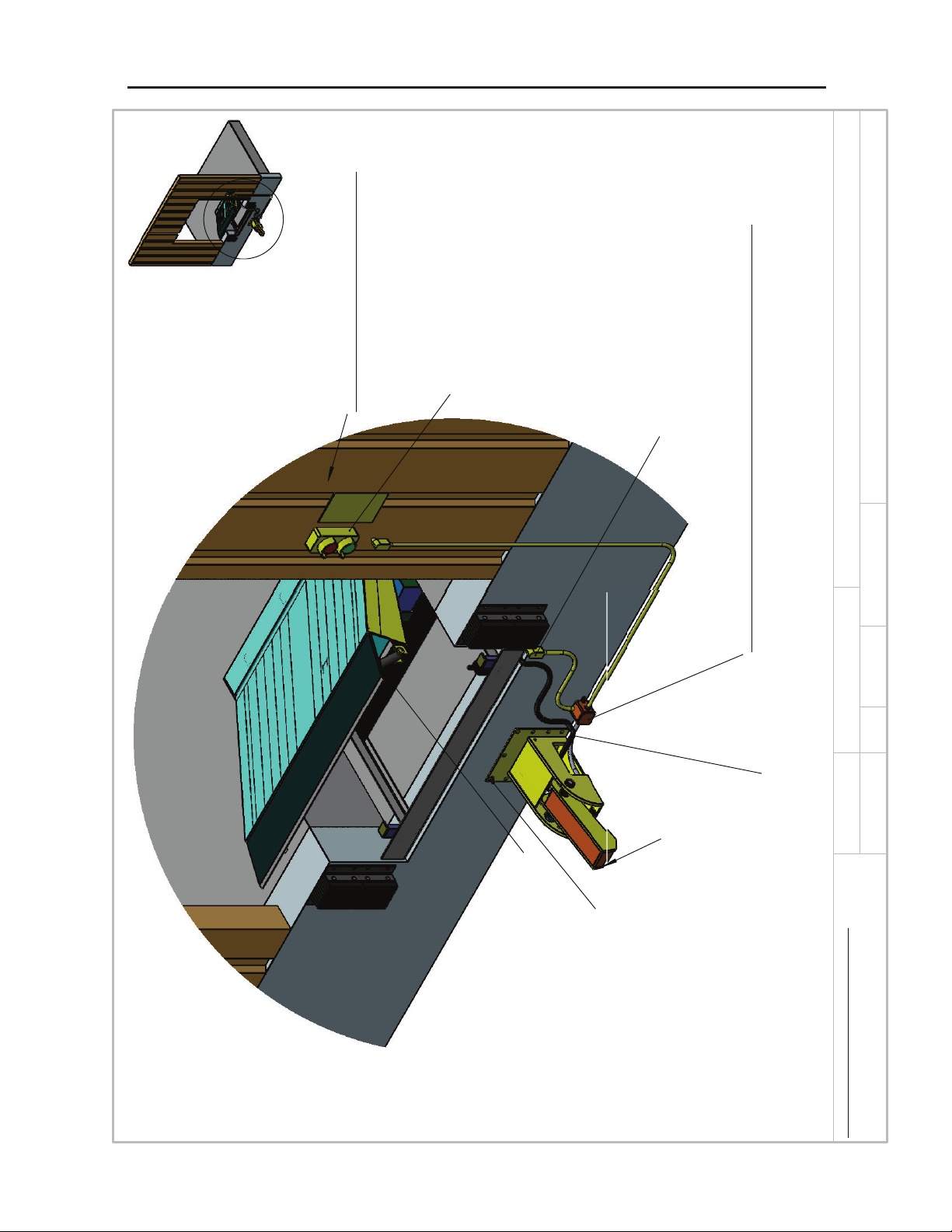
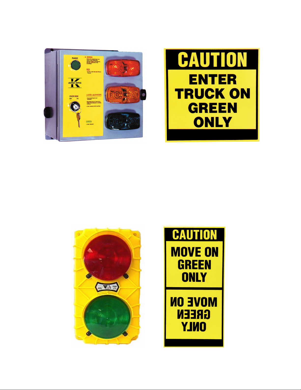
Interior Lights and Controls (See pg. 9)
ExteriorLights(Seepg.9)
ProximitySwitch(Seepg.14)
All of the following conditions must be true prior to operation:
1. Over head door is open.
2. Exterior green light is on.
3. Exterior red light is o.
4. Interior green and amber lights are o.
5. Interior red light is on.
6. Dock leveler and lip are in a stored position.
HYDRAULIC DOCK LEVELER:
ENGAGE (RAISE) RESTRAINT:
STEP 1: Press and hold raise button.
1.Exteriorlightchangesfromgreentored.
2. When restraint arm is fully raised, the dock leveler deck rises and
extendslip.
3. Interior light changes from red to green.
STEP 2: Release raise button.
1.Docklevelerlowerstotraileroorbygravity.
Restraint is now engaged and dock leveler is ready for loading/unloading.
DISENGAGE (LOWER) RESTRAINT:
STEP 1: Press and hold raise button.
1. Dock leveler deck raises, lip lowers to the vertical position for storing.
STEP 2: Release raise button.
1.Docklevelerlowersbygravitytoastored(closed)position.(Proximityswitchisactivated.)
2. Interior light changes from green to red.
3. Truck restraint arm fully lowers.
4.Exteriorlightchangesfromredtogreen.
Dock leveler and truck restraint are now in the stored poistion.
Truck or trailer is now free to depart.
MECHANICAL DOCK LEVELER:
ENGAGE (RAISE) RESTRAINT:
STEP 1: Operate mechanical dock leveler.
1. Pull release chain on dock leveler.
2.Exteriorlightchangesfromgreentored
3.AllInteriorlights(redamber&green)ashandalarmsounds.
4. Walk down dock leveler into truck.
STEP 2: Press and hold RAISE button.
1.Interiorlightschangefromallashingtoredonlyandalarmshutso.
2.Whenrestraintarmfullyraised(apprx.6-8sec.),releaseRAISEbutton.
3. Interior light changes to green.
Restraint is now engaged and dock leveler is ready for loading/unloading.

11
DISENGAGE (LOWER) RESTRAINT:
STEP 1: Return mechanical dock leveler to its stored position.
1. Pull release chain to raise dock leveler deck so lip lowers to the vertical position for storing.
2.Walkdocklevelerdowntoitsstored(closed)position.(Theproximityswitchisactivated)
3. Interior light changes from green to red.
4. Truck restraint arm fully lowers.
5.Exteriorlightchangesfromredtogreen.
Dock leveler and truck restraint are now in the stored poistion.
Truck or trailer is now free to depart.
ADDITIONAL SITUATIONS:
OVERNIGHT MODE:
1. Leave truck restraint engaged.
2. Store (close) the dock leveler.
3. Close the over head door.
ACTIVATING OVERNIGHT MODE:
-FROM STORED / CLOSED POSITION:
1. Press and hold down the raise button and the truck restraint will engage.
2. As soon as the dock leveler begins to rise, while holding the raise button, immediately
turn the override switch to ON.
3.Thenreleasetheraisebuttonbeforethedocklevelerlipextends.
4. The dock leveler will lower back to the stored (closed) position leaving the restraint
engaged.
5.Theexteriorandinteriorlightswillbered.
-FROM ENGAGED / WORKING POSITION:
1. Turn the over ride switch to the on position.
2. Press and hold down the raise button while dock leveler raises and the lip raises.
3. Release the raise button.
4. The dock leveler lowers by gravity to the stored position.
5.Theexteriorandinteriorlightswillbered.
IN THE EVENT OF A POWER FAILURE: (Manual Release)
1. Reach in side opening of truck restaint.
2. Turn the knob on the end of the valve mounted on the hydraulic cylinder until restraint
begins to lower. (see detail B on pg. 15)
3. When the restraint is completely lowered, close the valve mounted on the hydraulic cylinder
by turning the knob the opposite way.
4. The truck or trailer is free to move away.

12
OVERRIDE MODE INSTRUCTIONS:
ACTIVATING OVERRIDE MODE:
NOTE: RESTRAINT MUST BE IN THE STORED (CLOSED) POSITION
1. Turn the override switch to ON.
2.Exteriorlightschangefromgreentored.
3. The truck restraint is now in override mode.
WARNING: Restrain truck/trailer by some other means such as wheel chocks.
4. Press and hold down the raise button. (Alarm sounds)
5.Thedocklevelerdeckrisesandextendslip.
6. Interior lights change from red to amber. (Alarm stops)
7.Releasetheraisebuttonanddocklevelerwilllowerbygravitytothetraileroor.
8. Dock leveler is ready for loading or unloading.
WARNING: NEVERturntheoverrideswitchowhileloadingorunloadingtruck.
DEACTIVATING OVERRIDE MODE:
NOTE:Thedocklevelermustbeinthestored(closed)positionbeforeturningtheoverrideswitcho.
1. Press and hold down the raise button.
2. The dock leveler deck rises and lip retracts and hangs in a 90 degree position for storing.
3. Release the raise button.
4.Interiorlightschangefromambertoredonandashing.
5. The dock leveler lowers by gravity to the stored position.
6. Remove truck or trailer restraining device such as wheel chocks.
7.TurntheoverrideswitchtoOFF.Exteriorlightschangefromredtogreenonandashing.
8. The dock leveler and restraint are now in the stored position and the truck/trailer is free to leave.

13
TROUBLE SHOOTING
(When unit is not operating properly an alarm will sound)
PROBLEM: RESTRAINT WILL NOT RISE:
1. Check the power supply.
2. Check the circuit breakers.
3. Check for any hydraulic leaks.
4.Checktheuidlevelinthereservoir.
5. Check the power supply to the solenoid valve.
6. Check for loose or damaged wires.
PROBLEM: RESTRAINT WILL NOT LOWER:
1. Check the power supply.
2. Check the circuit breakers.
3. Check the power supply to the solenoid valve.
4. Check for obstructions in the restrainting arm
operating path.
5. Check for loose or damaged wires.
MANUAL LOWEREING VALVE
RESTRAINT ARM DRIFTS:
Truck Restraint in Engaged Position:
1. The truck restaint is in an engaged position and the overhead door is open.
2.Exteriorlights:Greenlightoandredlighton.
3.Interiorlights:Redandamberlightsareoandgreenlightison.
4.Thedocklevelerisinuseandthelipisextended(notinastoredposition).
The restraints arm starts to drift toward a stored position.
1. The restraint arm reaches the drift limit switch.
2.Exteriorlights:Redlightremainson.
3.Interiorlights:Greenlightturnso,andredlightturnson.
4. Alarm sounds.
Corrective Action:
1.Pressandholdtheraisebuttontore-positiontherestraintarm.
2.Insidelightschangetoredlightoandgreenlighton.(Alarmstopssounding)
3. The restraint arm engages the ICC bar of the truck or trailer and deck begins to rise.
4. Release raise button.

14
PROXIMITY SWITCH DIAGRAM
INTERIOR LIGHTS / CONTROL PANEL / SIGN
EXTERIOR LIGHTS / SIGNS
ITEM 14 ITEM 15
ITEM 12
ITEM 13

15
TRUCK RESTRAINT ASSEMBLY
& PARTS LIST
ITEM DESCRIPTION PART NO. QUANTITY
1MainBox HTR-2020-01 1
2 Cover HTR-2020-02 1
3Mian Arm HTR-2020-03 1
4 Main Shaft HTR-2020-04 1
5 Spring Shaft HTR-2020-05 1
6 Hydraulic Cylinder HTR-2020-06 1
7 Hydraulic Valve HTR-2020-07 1
8 Spring HTR-2020-08 2
9 Limit Switch HTR-2020-09 1
10 ProximitySwitch(Pg.14) HTR-2020-10 1
11 15’ Hydraulic Hose (Pg. 7) HTR-2020-11 1
12 ExteriorLight(Pg.14) HTR-2020-12 1
13 ExteriorSign(Pg.14) HTR-2020-13 1
14 Control Panel (Pg. 14) HTR-2020-14 1
15 Interior Sign (Pg. 14) HTR-2020-15 1

16
STANDARD ELECTRICAL SCHEMATIC

17
MAINTENANCE SCHEDULE
DAILY -Checkinsideandoutsidelightsforburnedoutbulbs
-Replaceburnedoutbulbsimmediately
-Removedebrisonoraroundtruckrestraint
-Removesnowandiceontruckrestraint
WEEKLY -Checkfulloperationofthetruckrestraintanddocklevelertoensure
there is no hesitation in the hydraulic system
-Anylossofuidwillaectthesafeoperationoftheequipment
QUARTERLY -Inspectthehydrauliccylinder,valveandhoseforanysignsofuidloss
-Inspectstructuralmembersforfailures(bendingorbrokenwelds)
-Addgrease(multipurposeEP-2orequivalent)togreasettingsatItems
4 & 5 (pg. 15)

18
SERVICE POLICY & WARRANTY
KOKE Inc. warrants that each KOKE manufactured product shall be free from defects
in materials and workmanship. Any part of this product which, under normal use and
maintenance, proves defective in material and workmanship within (12) twelve months
on mechanical components, (90) days on electrical components and (60) months on
structural components, provided that notice of any such defects and satisfactory proof
of defects is given by the buyer to the seller, with transportation prepaid, and seller’s
examinationprovedsuchparttobedefective.
KOKE’S OBLIGATION UNDER THIS WARRANTY IS LIMITED TO THE
REPLACEMENT OF DEFECTIVE COMPONENTS AT THE FACTORY, OR, AT THE
DISCRETION OF KOKE INC., AT A LOCATION DESIGNATED BY THE COMPANY.
KOKE INC. WILL NOT BE LIABLE FOR ANY LOSS, INJURY OR DAMAGE TO
PERSONS OR PROPERTY, NOR FOR DAMAGES OF ANY KIND RESULTING FROM
FAILURE OR DEFECTIVE OPERATION OF ANY MATERIALS OR EQUIPMENT.
NO OTHER WARRANTIES EXIST EXCEPT AS STATED HEREIN
KOKE INC. is constantly striving to improve the equipment we produce. Improvements
and necessary design changes will be made whenever KOKE Inc. believes
performance or operation of the equipment will be improved with no obligation to
incorporate any improvements to any equipment that may be in service.

19
THIS PAGE INTENTIONALLY LEFT BLANK

20
Koke Inc.
582 Queensbury Ave.
Queensbury, NY 12804
Phone:(800)535-5303
Fax:(888)231-5521
Email: [email protected]
Web: www.kokeinc.com
Koke Inc. is constantly striving to make a better product. As a result, the company reserves the right
to make changes and upgrades at any time without notice.
Copyright ©2020 Koke Incorporated
This manual suits for next models
1
Table of contents