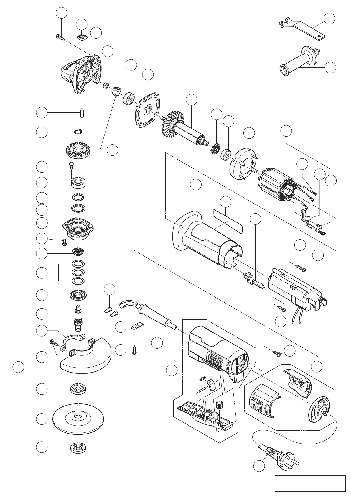
Koki Holdings G 10BYEQ2 User manual

PRODUCT NAME
Electronic Disc Grinder
Models
100 mm (4”)
G 10BYEQ2
115 mm
(4-1/2")
G 12BYEQ2
125 mm (5”)
G 13BYEQ2
G
REPAIR GUIDE ---------------------------------------------------------------------------------------------------------------- 1
1. Precautions on disassembly and reassembly ----------------------------------------------------------- 1
• Disassembly ------------------------------------------------------------------------------------------------- 1
• Reassembly -------------------------------------------------------------------------------------------------- 4
• Lubrication point and type of lubricant ----------------------------------------------------------------- 6
• Tightening torque ------------------------------------------------------------------------------------------- 6
• Checking after reassembly ------------------------------------------------------------------------------- 6
• Insulation test ------------------------------------------------------------------------------------------------ 6
• No-load current value -------------------------------------------------------------------------------------- 7
• Connecting diagram ---------------------------------------------------------------------------------------- 7
CONTENTS Page
G
CONFIDENTIAL
Oct. 2022
Overseas Sales Management Dept.
G 13BYEQ2

-1-
Fig. 1
WARNING: Before disassembly, be sure to turn off the power switch and disconnect the power cord
plug from the outlet.
1. Precautions on disassembly and reassembly
[Bold] numbers in the description below correspond to the item numbers in the parts list and exploded
assembly diagram of the Model G 10BYEQ2, {Bold} numbers to those of the Model G 12BYEQ2, and
<Bold> numbers to those of the Model G 13BYEQ2.
1. Disassembly of the filter set
(1) Use a flat-blade screwdriver to unclip the two clips joining the bottom and side filters of the Filter Set
[45]{48}<48>.
(2) Push out the bottom filter in the arrow direction and remove the two side filters as shown in Fig. 1.
2. Removal of the rotor, stator, and controller
(1) Loosen the Tapping Screw (W/Flange) D4 x 16 (Black) [44]{47}<47> and pull out the Tail Cover Set
[43]{46}<46>.
(2) Loosen the four Tapping Screws (W/Flange) D4 x 23 (Black) [1]{1}<1> that fix the Gear Cover Ass’y
[3]{3}<3> and remove the Rotor [7]{7}<7> from the Housing [33]{36}<36> together with the Bearing
Holder [6]{6}<6>.
(3) Loosen the Special Nut M6 [4] or Special Nut M7 {4}<4> and remove the pinion.
(4) Insert the J-204 hooks (Code No. 970983) of the J-204 bearing puller (Code No. 970982) into the
clearance between the Ball Bearing 628DD [5]{5}<5> and Bearing Holder [6]{6}<6> from both sides,
and then fix the J-204 hooks in place with the wing bolts.
(5) Put the J-204 bearing puller on an appropriate stand. Push down the rotor shaft with a hand press to
remove the Ball Bearing 628DD [5]{5}<5>. Then remove the Bearing Holder [6]{6}<6>.
(6) Remove the insulating tape from the connector between the Sensor PCB [13]{13}<13> and Controller
[37]{40}<40>, then remove the connector. Remove the Fastons [12]{12}<12> of Stator Ass’y (A)
[11]{11}<11> from the Controller [37]{40}<40>. Remove silicone rubber from the connector.
NOTE: Be careful not to damage the connectors when removing.
(7) Loosen the Tapping Screw (W/Flange) D4 x 35 (Black) [36]{39}<39> and Tapping Screw (W/Flange) D4
x 20 (Black) [38]{41}<41>. Remove the Controller [37]{40}<40> from the Housing [33]{36}<36>.
(8) Remove the Fan Guide [10]{10}<10> from the Housing [33]{36}<36>. Remove Stator Ass’y (A)
[11]{11}<11> from the Housing [33]{36}<36>.
(9) Insert the hooks of the J-204 bearing puller (Code No. 970982) into the clearance between the Ball
Bearing 608DD [9]{9}<9> and Dust Seal [8]{8}<8>, and then fix the hooks in place with the wing bolts.
REPAIR GUIDE
Disassembly
Side filter
Bottom filter
Push out.
Unclip.
Flat-blade screwdriver
Unclip.
Side filter

-2-
(10) Put the J-204 bearing puller on an appropriate stand. Push down the rotor shaft with a hand press to
remove the Ball Bearing 608DD [9]{9}<9>.
(11) Remove the Dust Seal [8]{8}<8> from the rotor shaft.
3. Removal of the gear (Model G 10BYEQ2)
(1) Loosen the four Seal Lock Screws (W/Sp. Washer) M4 x 12 [21] and remove Packing Gland (A) [20]
from the Gear Cover Ass’y [3].
(2) Remove the Retaining Ring for D12 Shaft [15].
(3) Hold the bottom surface of Packing Gland (A) [20] and push down Spindle (A) [25] 2 or 3 mm with a
hand press as shown in Fig. 2.
(4) Hold Packing Gland (A) [20] in the reverse direction and push Spindle (A) [25] back to the original
position as shown in Fig. 3.
(5) Insert the J-128 gear puller (Code No. 970904) or an iron plate between the gear and Packing Gland (A)
[20]. Push out Spindle (A) [25] with a hand press as shown in Fig. 4.
NOTE: Replace the Ball Bearing 6001DD [17] with new one because it is deformed by the gear
pull-out force at disassembly.
Push
Fig. 2
Push
J-128 gear puller (Code No. 970904)
or an iron plate
Push
Fig. 3
Fig. 4

-3-
Fig. 5
4. Removal of the gear (Models G 12BYEQ2 and G 13BYEQ2)
(1) Loosen the three Seal Lock Screws (W/Washer) M4 x 12 {18}<18> and the Seal Lock Screw (W/Sp.
Washer) M5 x 16 {20}<20>, and remove the Packing Gland {17}<17> from the Gear Cover Ass’y {3}<3>.
(2) Remove the Retaining Ring for D12 Shaft {15}<15> that secures the gear to the Spindle {27}<27>.
(3) When it is necessary to remove the gear from the Spindle {27}<27>, it is highly recommended that the
special repair tool J-245-3 sleeve I.D 42 (Code No. 307720) described below is utilized. Place the
assembly on the J-245-3 sleeve I.D 42 and press down on the top of the Spindle {27}<27> with a hand
press to remove the gear as shown in Fig. 5.
5. Removal of the cord
(1) Cut the two internal wires of the Cord [46]{49}<49> at the position nearest to the Connectors
[39]{42}<42>.
(2) Loosen the Tapping Screw (W/Flange) D4 x 16 [41]{44}<44> and remove the Cord Clip [40]{43}<43>
and Cord [46]{49}<49> from the Controller [37]{40}<40>.
Press
{27}<27>
{17}<17>
Gear
J-245-3 sleeve I.D 42

-4-
Reassembly can generally be conducted by reversing the disassembly procedure. However, special
attention should be given to the following items.
(1) Wipe off old grease inside the gear cover and surrounding parts completely. Apply 8 g of grease (Cosmo
KMC No. 1) to the teeth of the Gear and Pinion Set [32]{32}<32> so that the grease reaches each tooth
bottom.
(2) Apply 0.5 g of grease to the inside of the needle bearing when replacing the Gear Cover Ass'y [3]{3}<3>.
(3) Impregnate the Felt Packing [18] or Felt Packing (B) {21}<21> with machine oil.
(4) Mount Belleville Spring (A) [23] or Belleville Spring (B) {25}<25> in proper direction as shown in Fig. 6.
(5) When replacing the Rotor [7]{7}<7> and Ball Bearing 608DD [9]{9}<9>, press-fit the Dust Seal [8]{8}<8>
in proper direction until the end face of the Dust Seal [8]{8}<8> contacts the butting surface of the Rotor
[7]{7}<7>, and check that the Dust Seal [8]{8}<8> cannot turn freely.
NOTE: The Dust Seal [8]{8}<8> is an important element for improved dust protection of the Ball
Bearing 608DD [9]{9}<9>. Be sure to replace the Dust Seal [8]{8}<8> with a new one at
reassembly.
(6) Mount the Sensor PCB [13]{13}<13> to Stator Ass’y (A) [11]{11}<11> securely using the Tapping Screw
D2 x 8 (Black) [47]{50}<57>. Check that there is no rattling after mounting.
(7) Insert Stator Ass’y (A) [11]{11}<11> into the Housing [33]{36}<36> paying attention to the position of
the internal wires of Stator Ass’y (A) [11]{11}<11>. Be careful not to pinch the internal wires. After
inserting Stator Ass’y (A) [11]{11}<11>, push the black internal wire in between the ribs of the Housing
[33]{36}<36> as shown in Fig. 7.
(8) Align the protrusion of the Fan Guide [10]{10}<10> with the groove on the Housing [33]{36}<36> as
shown in Fig. 8 when inserting the Fan Guide [10]{10}<10> into the Housing [33]{36}<36>.
Reassembly
Fig. 6 • Mounting direction of belleville springs (A) and (B)
G 10BYEQ2 G 12BYEQ2/G 13BYEQ2
[23]
{25}<25>
Black
Blue
Red
Push in between the ribs.
Align the protrusion
with the groove.
Fig. 7 Fig. 8
[13]{13}<13>
[35]{38}<38>

-5-
Fig. 11
(9) To prevent damage to the Controller [37]{40}<40>, avoid contact of the Controller [37]{40}<40> with the
tip of the Switch Lever [35]{38}<38> when mounting the Controller [37]{40}<40> to the Housing
[33]{36}<36>. Also be careful not to pinch the internal wires.
(10) Insert the Fastons [12]{12}<12> of Stator Ass’y (A) [11]{11}<11> into the terminals of the Controller
[37]{40}<40> being careful of the internal wire color (in the order of red, blue, and black from the
housing side) and the position as shown in Fig. 9. Apply silicone rubber to the opening of the connectors
to prevent short circuit caused by metallic dust.
(11) Connect the connector of the Sensor PCB [13]{13}<13> to the connector of the Controller [37]{40}<40>
being careful of the inserting direction. After connecting, wind insulating tape around the connector 1.5
to 2 turns to prevent short circuit caused by exposure of the connector terminal. Fit the connector in the
groove of the heatsink to avoid contact of the internal wires with the switch portion as shown in Fig. 9.
(12) Wind insulating tape around the opening of the Connector [39]{42}<42> to prevent short circuit caused
by metallic dust.
(13) Be careful not to pinch the internal wires when mounting the Tail Cover Set [43]{46}<46>.
(14) Tighten the three Seal Lock Screws (W/Washer) M4 x 12 {18}<18>. Mount the Lever {34}<34> and
Retaining Ring D4 {35}<35> to the Lever Holder {19}<19>. Hook the Spring {33}<33> on the Lever
{34}<34>. Then tighten the Seal Lock Screw (W/Sp. Washer) M5 x 16 {20}<20>.
(15) Engage the clip on the side filter with the vent air hole and align the side filter with the Tail Cover Set
[43]{46}<46>. Insert the bottom filter and push in the clips with the side filters as shown in Fig. 11.
1. Engage the clip on the side
filter with the vent air hole.
3. Insert the bottom filter.
4. Push in the clips with
the side filters.
2. Align the side filter with the
Tail Cover Set [43]{46}<46>.
Apply silicone rubber to the
opening of the connectors.
Be careful of the inserting direction. After connecting,
wind insulating tape around the connector 1.5 to 2 turns.
Fit the connector in the groove of the heatsink to
avoid contact with the Switch Lever [35]{38}<38>.
Black
Blue
Red
Black
Red
Black
Red
Fig. 9 Fig. 10
Sensor PCB
[13]{13}<13> side
Controller
[37]{40}<40> side

-6-
Please purchase the following grease as necessary.
Item Registered part name Net weight Code No.
Cosmo KMC No. 1 Grease (Cosmo grease KMC No. 1) 75 g 75 g 378134
Item No. Part name Tightening torque
N•m kgf•cm
[16] Slotted Hd. Screw (Seal Lock) M4 1.8 ± 0.5 18 ± 4
{18}<18> Seal Lock Screw (W/Washer) M4 x 12 1.8 ± 0.5 18 ± 4
{20}<20> Seal Lock Screw (W/Sp. Washer) M5 x 16 3.4 ± 0.7 35 ± 7
[1]{1}<1> Tapping Screw (W/Flange) D4 x 23 (Black) 2.0 ± 0.5 20 ± 5
[36]{39}<39> Tapping Screw (W/Flange) D4 x 35 (Black) 2.0 ± 0.5 20 ± 5
[38]{41}<41> Tapping Screw (W/Flange) D4 x 20 (Black) 2.0 ± 0.5 20 ± 5
[41]{44}<44> Tapping Screw (W/Flange) D4 x 16 2.0 ± 0.5 20 ± 5
[44]{47}<47> Tapping Screw (W/Flange) D4 x 16 (Black) 2.0 ± 0.5 20 ± 5
[4] Special Nut M6 4.9 ± 1.0 50 ± 10
{4}<4> Special Nut M7 7.4 ± 0.5 75 ± 5
[47]{50}<57> Tapping Screw D2 x 8 (Black) 0.5 ± 0.1 5 ± 1.0
[22] Sleeve (F) 25 ± 5 250 ± 50
{24}<24> Sleeve 25 ± 5 250 ± 50
Check the following after reassembly.
(1) Check that the motor does not start by pulling the switch lever in the off lock status.
(2) Check that the brake functions properly.
(3) Check that the grinder is not turned on by inserting the power cord plug into an outlet with the switch
lever pulled. Then, release the switch lever and pull it again to check that the grinder is turned on.
Measure the insulation resistance and dielectric strength after reassembly.
• Insulation resistance: 10 MΩor higher (as measured with a 500 VDC megohm tester)
• Dielectric strength: 2,500 VAC/minute, with no abnormalities
Tightening torque
Checking after reassembly
Lubrication point and type of lubricant
Insulation test

-7-
After no-load operation for 30 minutes, the no-load current values should be as follows.
Voltage 120 V 220V 230 V 240 V
Current 2.3 to 3.1 A 1.2 to 1.7 A 1.1 to 1.6 A 1.1 to 1.5 A
No-load current value
Fig. 12
Black
Sensor PCB
Red
Connecting diagram
Controller
White
Black
Black Red
U
V
W
White or blue
Black or brown

M O D E L
Rev.1 G10BYEQ2
47
1
2
3
4
5
6
7
8
9
10 11
14
15
16
17
20
21
18
19
22
23
26
27
28
29
30
31
32
33
34
36
37
24
25
35
38
39
40
41
42
44
46
501
502
43
45
13
12

ITEM CODE NO.
NO. NO. USED
1 328643 TAPPING SCREW (W/FLANGE) D4 X 23 (BLACK) 4
2 378809 PUSHING BUTTON 1
3 378810 GEAR COVER ASS'Y 1 INCLUD. 2, 14
4 309191 SPECIAL NUT M6 1
5 378615 BALL BEARING 628DD 1
6 378812 BEARING HOLDER 1
7 361177 ROTOR 1
8 379725 DUST SEAL 1
9 608DDM BALL BEARING 608DD 1
10 378808 FAN GUIDE 1
11 341130E STATOR ASS'Y (A) 220 V-240 V 1 INCLUD. 12, 13, 47
12 370131 FASTON 3
13 378813 SENSOR PCB 1
14 301943 LOCK PIN 1
15 939542 RETAINING RING FOR D12 SHAFT (10 PCS.) 1
16 371814 SLOTTED HD. SCREW (SEAL LOCK) M4 2
17 6001DD BALL BEARING 6001DDCMPS2L 1
18 376786 FELT PACKING 1
19 378823 WASHER (F) 1
20 378814 PACKING GLAND (A) 1
21 307127 SEAL LOCK SCREW (W/SP. WASHER) M4 X 12 4
22 378824 SLEEVE (F) 1
23 371667 BELLEVILLE SPRING (A) 3
24 371668 SUPPORT BODY (A) 1
25 371665 SPINDLE (A) 1
26 301949 SET PLATE 1
27 308386 MACHINE SCREW (W/SP. WASHER) M5 X 16 (BLACK) 2
28 331085 WHEEL GUARD ASS'Y 1 INCLUD. 26, 27
29 373072 WHEEL WASHER (A) 1
30 316820 D. C. WHEELS 100 MM X 4T A36Q (25 PCS.) 1
31 339578 WHEEL NUT M10 1
32 338338 GEAR AND PINION SET 1
33 378826 HOUSING 1
34 NAME PLATE 1
35 379737 SWITCH LEVER 1
36 303694 TAPPING SCREW (W/FLANGE) D4 X 35 (BLACK) 1
37 379729 CONTROLLER (B) 220 V-240 V 1
38 301653 TAPPING SCREW (W/FLANGE) D4 X 20 (BLACK) 1
39 959140 CONNECTOR 50091 (10 PCS.) 2
40 338334 CORD CLIP 1
41 984750 TAPPING SCREW (W/FLANGE) D4 X 16 1
42 953327 CORD ARMOR D8.8 1
43 379732 TAIL COVER SET 1
44 307811 TAPPING SCREW (W/FLANGE) D4 X 16 (BLACK) 1
45 379204 FILTER SET 1
*46 500247Z CORD 1 (CORD ARMOR D8.8) FOR SIN (PLUG: 2 PIN)
*46 500423Z CORD 1 (CORD ARMOR D8.8) FOR SIN (PLUG: 3 PIN)
47 329623 TAPPING SCREW D2 X 8 (BLACK) 2
501 313933 WRENCH 1
502 378279 SIDE HANDLE 1
601 314051 SANDING DISCS 100 MM C-P16 (10 PCS.) 1
602 314052 SANDING DISCS 100 MM C-P20 (10 PCS.) 1
603 314053 SANDING DISCS 100 MM C-P24 (10 PCS.) 1
604 314054 SANDING DISCS 100 MM C-P30 (10 PCS.) 1
605 314055 SANDING DISCS 100 MM C-P36 (10 PCS.) 1
606 314056 SANDING DISCS 100 MM C-P40 (10 PCS.) 1
607 314057 SANDING DISCS 100 MM C-P50 (10 PCS.) 1
608 314058 SANDING DISCS 100 MM C-P60 (10 PCS.) 1
609 314059 SANDING DISCS 100 MM C-P80 (10 PCS.) 1
610 314060 SANDING DISCS 100 MM C-P100 (10 PCS.) 1
611 314061 SANDING DISCS 100 MM C-P120 (10 PCS.) 1
612 935513 WASHER NUT M10 X P1.5 1
613 936548 WASHER 1
614 936558Z RUBBER PAD 1
615 302098 GUIDE BASE 1
616 323918 DUST COLLECTION ADAPTER (DISC GRINDER) 1
DESCRIPTION REMARKS
STANDARD ACCESSORIES
OPTIONAL ACCESSORIES

M O D E L
Rev.1 G12BYEQ2
50
1
2
3
4
5
6
7
8
9
10 11
14
15
16
17
18
19
20
21
22
23
27
28
29
32
36
37
39
40
41
38
43
44
45
47
49
501
502
48
30
31
33
34
35
46
24
25
26
42
13
12

ITEM CODE NO.
NO. NO. USED
1 328643 TAPPING SCREW (W/FLANGE) D4 X 23 (BLACK) 4
2 378809 PUSHING BUTTON 1
3 378811 GEAR COVER ASS'Y 1 INCLUD. 2, 14
4 301941 SPECIAL NUT M7 1
5 378615 BALL BEARING 628DD 1
6 378812 BEARING HOLDER 1
7 361178 ROTOR 1
8 379725 DUST SEAL 1
9 608DDM BALL BEARING 608DD 1
10 378808 FAN GUIDE 1
11 341130C STATOR ASS'Y (A) 110 V-120 V 1 INCLUD. 12, 13, 50
12 370131 FASTON 3
13 378813 SENSOR PCB 1
14 301943 LOCK PIN 1
15 939542 RETAINING RING FOR D12 SHAFT (10 PCS.) 1
16 375899 O-RING 1
17 378815 PACKING GLAND 1
18 328628 SEAL LOCK SCREW (W/WASHER) M4 X 12 3
19 379733 LEVER HOLDER 1
20 307046 SEAL LOCK SCREW (W/SP. WASHER) M5 X 16 1
21 378822 FELT PACKING (B) 1
22 379734 FRINGER 1
23 375900 O-RING 1
24 378821 SLEEVE 1
25 371673 BELLEVILLE SPRING (B) 1
26 371674 SUPPORT BODY (B) 1
27 378820 SPINDLE (C) 1
28 375903 WHEEL GUARD 1
29 373071 WHEEL WASHER (E) 1
30 D. C. WHEELS 115 MM 1
31 937923P WHEEL NUT 5/8"-11UNC 1
32 379738 GEAR AND PINION SET 1
33 376229 SPRING 1
34 379736 LEVER 1
35 6685336 RETAINING RING D4 1
36 378826M HOUSING 1
37 NAME PLATE 1
38 379737 SWITCH LEVER 1
39 303694 TAPPING SCREW (W/FLANGE) D4 X 35 (BLACK) 1
40 379731 CONTROLLER (A) 120 V 1
41 301653 TAPPING SCREW (W/FLANGE) D4 X 20 (BLACK) 1
42 959140 CONNECTOR 50091 (10 PCS.) 2
43 338334 CORD CLIP 1
44 984750 TAPPING SCREW (W/FLANGE) D4 X 16 1
45 953327 CORD ARMOR D8.8 1
46 379732 TAIL COVER SET 1
47 307811 TAPPING SCREW (W/FLANGE) D4 X 16 (BLACK) 1
48 379204 FILTER SET 1
49 500434Z CORD 1
50 329623 TAPPING SCREW D2 X 8 (BLACK) 2
501 938332Z WRENCH 1
502 378279M SIDE HANDLE 1
601 938317 RUBBER PAD 1
602 938318 WASHER NUT 1
DESCRIPTION REMARKS
STANDARD ACCESSORIES
OPTIONAL ACCESSORIES

M O D E L
Rev.1 G13BYEQ2
57
1
2
3
4
5
6
7
8
9
10 11
14
15
16
17
18
19
20
21
22
23
27
28
29
32
36
37
39
40
41
38
43
44
45
47
49
501 502
48
30
31
33
34
35
502
46
24
25
26
42
13
12
503

ITEM CODE NO.
NO. NO. USED
1 328643 TAPPING SCREW (W/FLANGE) D4 X 23 (BLACK) 4
2 378809 PUSHING BUTTON 1
3 378811 GEAR COVER ASS'Y 1 INCLUD. 2, 14
4 301941 SPECIAL NUT M7 1
5 378615 BALL BEARING 628DD 1
6 378812 BEARING HOLDER 1
7 361178 ROTOR 1
8 379725 DUST SEAL 1
9 608DDM BALL BEARING 608DD 1
10 378808 FAN GUIDE 1
*11 341130C STATOR ASS'Y (A) 110 V-120 V 1 INCLUD. 12, 13, 57
*11 341130E STATOR ASS'Y (A) 220 V-240 V 1 INCLUD. 12, 13, 57
12 370131 FASTON 3
13 378813 SENSOR PCB 1
14 301943 LOCK PIN 1
15 939542 RETAINING RING FOR D12 SHAFT (10 PCS.) 1
16 375899 O-RING 1
17 378815 PACKING GLAND 1
18 328628 SEAL LOCK SCREW (W/WASHER) M4 X 12 3
19 379733 LEVER HOLDER 1
20 307046 SEAL LOCK SCREW (W/SP. WASHER) M5 X 16 1
21 378822 FELT PACKING (B) 1
22 379734 FRINGER 1
23 375900 O-RING 1
24 378821 SLEEVE 1
25 371673 BELLEVILLE SPRING (B) 1
26 371674 SUPPORT BODY (B) 1
*27 378819 SPINDLE (B) 1
*27 378820 SPINDLE (C) 1 FOR USA, CAN
28 375904 WHEEL GUARD 1
*29 371677 WHEEL WASHER (C) 1
*29 373071 WHEEL WASHER (E) 1 FOR USA, CAN
*30 316822 D. C. WHEELS 125 MM A36Q (25 PCS.) 1 FOR AUS, NZL
*30 D. C. WHEELS 125 MM 1 FOR USA, CAN
*31 339579 WHEEL NUT M14 1
*31 937923P WHEEL NUT 5/8"-11UNC 1 FOR USA, CAN
32 379738 GEAR AND PINION SET 1
33 376229 SPRING 1
34 379736 LEVER 1
35 6685336 RETAINING RING D4 1
*36 378826 HOUSING 1
*36 378826M HOUSING 1 FOR USA, CAN
37 NAME PLATE 1
38 379737 SWITCH LEVER 1
39 303694 TAPPING SCREW (W/FLANGE) D4 X 35 (BLACK) 1
*40 379731 CONTROLLER (A) 120 V 1
*40 379729 CONTROLLER (B) 220 V-240 V 1
41 301653 TAPPING SCREW (W/FLANGE) D4 X 20 (BLACK) 1
42 959140 CONNECTOR 50091 (10 PCS.) 2
43 338334 CORD CLIP 1
44 984750 TAPPING SCREW (W/FLANGE) D4 X 16 1
45 953327 CORD ARMOR D8.8 1
46 379732 TAIL COVER SET 1
47 307811 TAPPING SCREW (W/FLANGE) D4 X 16 (BLACK) 1
48 379204 FILTER SET 1
*49 500247Z CORD 1 (CORD ARMOR D8.8)
*49 500439Z CORD 1 (CORD ARMOR D8.8) FOR AUS, NZL
*49 500434Z CORD 1 (CORD ARMOR D8.8) FOR USA, CAN
57 329623 TAPPING SCREW D2 X 8 (BLACK) 2
501 938332Z WRENCH 1
*502 336865 SIDE HANDLE 1
*502 378279M SIDE HANDLE 1 FOR USA, CAN
*503 379735 GUARD CLIP (D125) 1 FOR EUROPE, AUS, NZL
*601 316822 D. C. WHEELS 125 MM A36Q (25 PCS.) 1 FOR EUROPE
*602 937826Z WASHER NUT 1
*602 938318 WASHER NUT 1 FOR USA, CAN
*603 937825Z RUBBER PAD 1
*603 938317 RUBBER PAD 1 FOR USA, CAN
*604 314062 SANDING DISCS 125 MM C-P16 (10 PCS.) 1 EXCEPT FOR USA, CAN
*605 314063 SANDING DISCS 125 MM C-P20 (10 PCS.) 1 EXCEPT FOR USA, CAN
DESCRIPTION REMARKS
STANDARD ACCESSORIES
OPTIONAL ACCESSORIES

ITEM CODE NO.
NO. NO. USED
DESCRIPTION REMARKS
*606 314064 SANDING DISCS 125 MM C-P24 (10 PCS.) 1 EXCEPT FOR USA, CAN
*607 314065 SANDING DISCS 125 MM C-P30 (10 PCS.) 1 EXCEPT FOR USA, CAN
*608 314066 SANDING DISCS 125 MM C-P36 (10 PCS.) 1 EXCEPT FOR USA, CAN
*609 314067 SANDING DISCS 125 MM C-P40 (10 PCS.) 1 EXCEPT FOR USA, CAN
*610 314068 SANDING DISCS 125 MM C-P50 (10 PCS.) 1 EXCEPT FOR USA, CAN
*611 314069 SANDING DISCS 125 MM C-P60 (10 PCS.) 1 EXCEPT FOR USA, CAN
*612 314070 SANDING DISCS 125 MM C-P80 (10 PCS.) 1 EXCEPT FOR USA, CAN
*613 314071 SANDING DISCS 125 MM C-P100 (10 PCS.) 1 EXCEPT FOR USA, CAN
*614 314072 SANDING DISCS 125 MM C-P120 (10 PCS.) 1 EXCEPT FOR USA, CAN
*615 332788 WHEEL GUARD (FOR CUTTING) 1 EXCEPT FOR USA, CAN
*616 332787 WHEEL GUARD BASE SET 1 EXCEPT FOR USA, CAN
617 339775 GREASE (COSMO MOLYBDENUM NO. 1) 400 G 1
This manual suits for next models
2
Table of contents
Other Koki Holdings Grinder manuals