Koki Holdings G 12SE3 User manual

G
REPAIR GUIDE ---------------------------------------------------------------------------------------------------------------- 1
1. Precautions on disassembly and reassembly ----------------------------------------------------------- 1
• Disassembly -------------------------------------------------------------------------------------------------- 1
• Reassembly -------------------------------------------------------------------------------------------------- 3
• Lubrication point and type of lubricant ----------------------------------------------------------------- 7
• Tightening torque -------------------------------------------------------------------------------------------- 7
• Checking after reassembly -------------------------------------------------------------------------------- 7
• Insulation test ------------------------------------------------------------------------------------------------ 7
• No-load current value---------------------------------------------------------------------------------------- 8
• Wiring diagram -----------------------------------------------------------------------------------------------8
STANDARD REPAIR TIME (UNIT) SCHEDULES -------------------------------------------------------------------- 9
CONTENTS Page
G
PRODUCT NAME
Disc Grinder
Models
115 mm (4-1/2”)
G 12SE3, G 12SE3(S)
125 mm (5”)
G 13SE3, G 13SE3(S)
CONFIDENTIAL
Apr. 2020
Overseas Sales Management Dept.

-1-
WARNING: Before attempting disassembly, be sure to turn off the power switch and disconnect the
power cord plug from the outlet.
1. Precautions on disassembly and reassembly
[Bold] numbers in the description below correspond to the item numbers in the parts list and exploded
assembly diagram for the Models G 12SE3 and G 12SE3(S), and <Bold> numbers to those for the Models
G 13SE3 and G 13SE3(S).
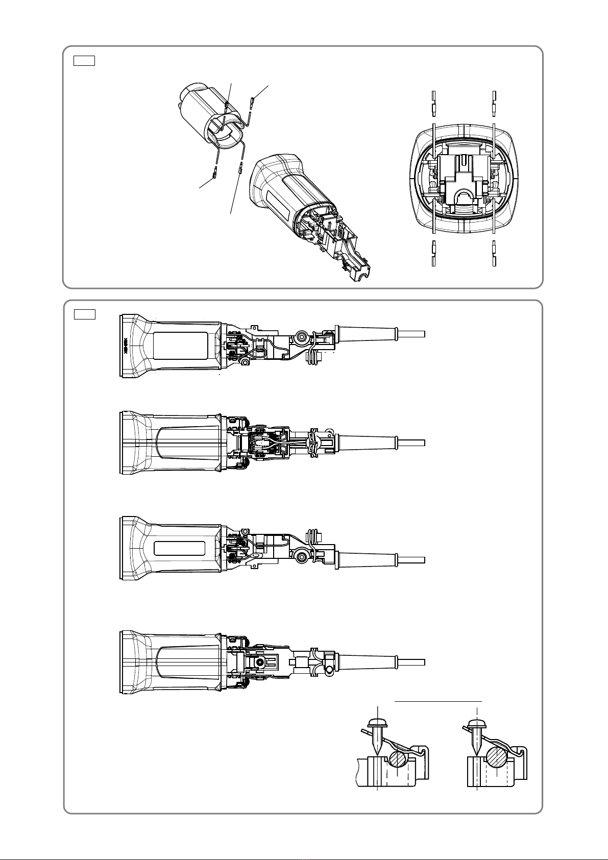
1. Removal of the armature and stator
(1) Loosen the two Tapping Screws (W/Flange) D4 x 35 [34]<34> and Tapping Screw (W/Flange) D4 x 20
[35]<35>, then pull out Tail Cover (B) [44]<44> and Tail Cover (A) [47]<47>. Remove the Carbon
Brushes (1 Pair) [40]<40>[48]<48> from the Brush Holders [42]<42>.
(2) Loosen the four Seal Lock Screws (W/Sp. Washer) M4 x 14 [7]<7> and remove the Packing Gland
[6]<6> and Lever Holder [8]<8>.
(3) Loosen the four Tapping Screws (W/Flange) D4 x 25 [1]<1> that fix the Gear Cover [2]<2> to remove
the Armature [24]<24> from the Housing [36]<36> together with the Diffuser [23]<23>. At this time,
check that the Rubber Bushing [33]<33> is fitted in the housing ball bearing chamber.
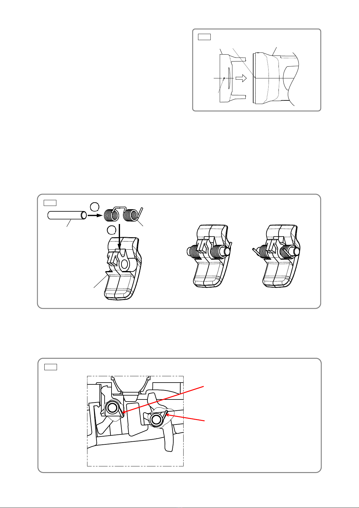
(4) Carefully wrap the Armature [24]<24> with a soft, clean rag to protect it from being damaged, and clamp
it securely in a vise. Then remove the Special Nut M7 [18]<18> and extract the Gear and Pinion Set
[25]<25>.
(5) Disconnect the four internal wires of the Stator [30]<30> from the Pushing Button Switch [43]<43> and
Brush Holders [42]<42>.
(6) Remove the Fan Guide [29]<29> and Stator [30]<30> from the Housing [36]<36>.
NOTE: • If the Stator [30]<30> is hard to be removed from the Housing [36]<36>, heat the Housing
[36]<36> up to about 60°C to facilitate removal. Then pull out the Rubber Bushing
[33]<33>.
• Each internal wire of the Stator [30]<30> is covered with a glass tube. Do not bend the
internal wires repeatedly and do not peel off the glass tubes when removing the Stator
[30]<30> from the Housing [36]<36>. Otherwise, the internal wires may be disconnected.
• Do not apply excessive force to the terminals of the Stator [30]<30> when removing them
from the Pushing Button Switch [43]<43> and Brush Holders [42]<42>. Otherwise, the
terminals of the Stator [30]<30> may be broken.
2. Removal of the rubber bushing
Insert the special repair tool J-201 spring hook (Code No. 970977) between the Rubber Bushing [33]<33>
assembled in the Housing [36]<36> and the housing ball bearing chamber, and then pull out the Rubber
Bushing [33]<33>.
3. Removal of the dust seal
(1) Insert the hooks of the J-204 bearing puller between the Ball Bearing 698SS [32]<32> and the Dust Seal
[31]<31> and fix the hooks with the wing bolts.
NOTE: Be careful not to insert the hooks excessively.
(2) Put the bearing puller on an appropriate stand. Press down on the armature shaft with a hand press and
pull out the Ball Bearing 698SS [32]<32>.
(3) Pull out the Dust Seal [31]<31> from the armature shaft.
Disassembly
REPAIR GUIDE

-2-
4. Removal of the gear and spindle
(1) Loosen the four Seal Lock Screws (W/Sp. Washer) M4 x 14 [7]<7> and remove the Packing Gland
[6]<6> from the Gear Cover [2]<2>.
(2) Remove the Retaining Ring for D12 Shaft [4]<4> that secures the gear to the Spindle [12]<12>.
(3) When it is necessary to remove the gear from the Spindle [12]<12>, it is highly recommended that the
special repair tool J-245-3 sleeve (Code No. 307720) described below is utilized. Place the assembly on
a sleeve that matches the dimension of the Packing Gland [6]<6> and press down on the top of the
Spindle [12]<12> with a hand press to remove the gear as shown in Fig. 1.
5. Removal of the off lock lever and on lock lever
(1) After removing the Switch Lever [55]<55> from the Housing [36]<36>, remove the Off Lock Lever
[54]<54> from the bottom of the Switch Lever [55]<55>. The Pin [52]<52> and Spring [53]<53> are
removed together with the Off Lock Lever [54]<54>.
(2) Push the Pin [49]<49> to remove the On Lock Lever [51]<51>.
Fig. 1
J-245-3 sleeve
Press
[12]<12>
[6]<6>
Gear

-3-
Reverse the disassembly procedure to reassemble. Note the following points.
(1) Rub grease into the teeth of the Gear and Pinion Set [25]<25> with your fingers so that the grease
reaches each tooth bottom. Note that under-lubricated Gear and Pinion Set [25]<25> may wear at a
faster rate.
(2) When replacing the Armature [24]<24> and the Ball Bearing 698SS [32]<32> on the commutator side,
press the Dust Seal [31]<31> in while carefully noting its direction until the end face of the Dust Seal
[31]<31> contacts the butting surface of the Armature [24]<24>, and check that the Dust Seal [31]<31>
cannot turn freely. (See Fig. 2.) The Dust Seal [31]<31> is an important element for improved dust
protection of the Ball Bearing 698SS [32]<32>. Be sure to replace the Dust Seal [31]<31> with new one
at every disassembly work. Fit the Rubber Bushing [33]<33> into the housing ball bearing chamber
before installing the Armature [24]<24>. (See Fig. 3.)
(3) When installing the Stator [30]<30> into the Housing [36]<36>, insert it while being careful about
correctly placing the internal wires of the Stator [30]<30> as shown in Fig. 4. Connect the four internal
wires of the Stator [30]<30> correctly as shown in Fig. 5.
NOTE: • Be careful not to put the internal wire of the Carbon Brush (1 Pair) [40]<40>[48]<48> on
the top of the Brush Holders [42]<42> when connecting the internal wires of the Stator
[30]<30> or when connecting the Carbon Brush (1 Pair) [40]<40>[48]<48>.
• Each internal wire of the Stator [30]<30> is covered with a glass tube. Do not bend the
internal wires repeatedly and do not peel off the glass tubes when mounting the Stator
[30]<30> to the Housing [36]<36>. Otherwise, the internal wires may be disconnected.
• Do not apply excessive force to the terminals of the Stator [30]<30> when inserting them
into the Pushing Button Switch [43]<43> and Brush Holders [42]<42>. Otherwise, the
terminals of the Stator [30]<30> may be broken.
Reassembly
Fig. 2 Fig. 3
Housing ball bearing chamber
[33]<33>
About 4.5 mm
About 0.6 mm (reference)
[31]<31>
Armature shaft
[32]<32>

-4-
Fig. 5
Direction of the cord clip
For 110 V
For 120 V, 230 V, and 240 V
Fig. 4
Connect to the Brush Holder [42]<42>.
Connect to the Pushing Button Switch [43]<43>.
Connect to the Brush Holder [42]<42>.

-5-
Fig. 6
(4) Be sure to soak the inner diameter of the Felt
Packing [9]<9> with machine oil. Otherwise, its dust
sealing function will fail to work properly, resulting in
premature damage to the ball bearing of the Packing
Gland [6]<6>. Wipe the Felt Packing [9]<9> lightly
with a rag before assembling.
(5) Mount the Fan Guide [29]<29> in proper direction by
matching the gate mark of the Fan Guide [29]<29>
with the parting line of the Housing [36]<36> as show
in Fig. 6.
(6) Mount the Off Lock Lever [54]<54> and On Lock Lever [51]<51> according to the following procedure.
NOTE: Some models are not equipped with the On Lock Lever [51]<51> depending on the
specifications.
(a) Put the Spring [53]<53> on the Off Lock Lever [54]<54> and insert the Pin [52]<52> as shown in Fig.
7. Use a flat-blade screwdriver to push the Pin [52]<52> in the groove on the back of the Switch
Lever [55]<55>.
NOTE: Be sure to align the end of the Spring [53]<53> with the slope of the Switch Lever
[55]<55>. Otherwise, the Off Lock Lever [54]<54> does not move smoothly.
(b) Put the Spring [50]<50> and On Lock Lever [51]<51> on the Housing [36]<36>. Then insert the Pin
[49]<49>.
(c) Check that the Spring [50]<50> is mounted in the proper position as shown in Fig. 8. Then mount the
Switch Lever [55]<55> to the Housing [36]<36>.
Gate mark
Parting line [36]<36>
[29]<29>
Fig. 7
Correct
mounting
Wrong
mounting
2
[53]<53>
1
[52]<52>
[54]<54>
Fig. 8
Align the end of the Spring [50]<50>
with the slope of the Housing [36]<36>.
Align the end of the Spring [53]<53> with
the slope of the Switch Lever [55]<55>.

-6-
(7) When mounting Tail Cover (A) [47]<47> and Tail Cover (B) [44]<44>, check the position of the Cord
[45]<45>, pigtail of the Carbon Brush (1 Pair) [40]<40>[48]<48>, and internal wires of the Noise
Suppressor [38]<38> as shown in Fig. 9.
NOTE: • Be careful not to sandwich the Cord [45]<45> and the internal wires of the Noise
Suppressor [38]<38> between Tail Cover (A) [47]<47> and Tail Cover (B) [44]<44>. Fit
the Cord [45]<45> in the groove of the Housing [36]<36>.
• Be careful not to put the pigtail of the Carbon Brush (1 Pair) [40]<40>[48]<48> on the
top of the Brush Holders [42]<42> when mounting Tail Cover (A) [47]<47> and Tail
Cover (B) [44]<44>. Before mounting Tail Cover (A) [47]<47> and Tail Cover (B) [44]<44>,
check the pigtail position.
• Mount the Ferrite Core [57]<57> as shown in Fig. 10.
(8) Tighten three of the four Seal Lock Screws (W/Sp. Washer) M4 x 14 [7]<7> except the one for securing
the Lever Holder [8]<8>. Mount the Lever [27]<27> and Retaining Ring D4 [28]<28> to the Lever Holder
[8]<8>. Hook the Spring [26]<26> on the Lever [27]<27>. Then tighten the remaining Seal Lock Screw
(W/Sp. Washer) M4 x 14 [7]<7>.
Fig. 9
Prope
r
Imprope
r
Check that the pigtail is not put on the Brush
Holder [42]<42> before mounting Tail Cover
(A) [47]<47> and Tail Cover (B) [44]<44>.
z
Do not sandwich the Cord [45]<45> and the
internal wires of the Noise Suppressor
[38]<38> between Tail Cover (A) [47]<47>
and Tail Cover (B) [44]<44>.
Fig. 10
Wind the Cord [45]<45> two
turns around the Ferrite Core
[57]<57>.

-7-
NOTE: Use a brush when rubbing grease.
(1) When replacing the Gear Cover [2]<2>, lubricate the inner circumference of the needle bearing with
0.3 g of Cosmo Molybdenum No. 1 grease.
(2) Rub 18 g of Cosmo Molybdenum No. 1 grease into the pinion chamber of the Gear Cover [2]<2>.
(3) Rub 2 g of Cosmo Molybdenum No. 1 grease into the teeth of the gear.
(4) Rub 0.7 g of Cosmo Molybdenum No. 1 grease into the teeth of the pinion.
Item No. Part name Tightening torque
N•m lbf•ft kgf•cm
[7]<7> Seal Lock Screw (W/Sp. Washer) M4 x 14 1.8 ± 0.4 1.3 ± 0.3 18 ± 4
[18]<18> Special Nut M7 7.4 ± 0.5 5.5 ± 0.4 75 ± 5
[34]<34> Tapping Screw (W/Flange) D4 x 35 (Black) 2.0 ± 0.5 1.5 ± 0.4 20 ± 5
[35]<35> Tapping Screw (W/Flange) D4 x 20 (Black) 2.0 ± 0.5 1.5 ± 0.4 20 ± 5
[39]<39> Tapping Screw D3 x 8 0.74 0.54 7.5
[59]<59> Tapping Screw (W/Flange) D4 x 12 2.0 ± 0.5 1.5 ± 0.4 20 ± 5
Be sure to check the following after mounting the Off Lock Lever [54]<54> and On Lock Lever [51]<51>.
• Check that the Off Lock Lever [54]<54> moves smoothly between the lock position and the unlock position.
Release the Switch Lever [55]<55> and check that the motor stops immediately and the Off Lock Lever
[54]<54> moves to the lock position smoothly.
• Check that the motor does not start by pulling the Switch Lever [55]<55> when the Off Lock Lever [54]<54>
is in the lock position.
• While pulling the Switch Lever [55]<55>, move the On Lock Lever [51]<51> to the on lock position. Check
that the Switch Lever [55]<55> does not return to the original position by releasing the Switch Lever
[55]<55>.
Measure the insulation resistance and dielectric strength after reassembly.
• Insulation resistance: 7 MΩor higher (as measured with a 500 VDC megohm tester)
• Dielectric strength: 4,000 VAC/minute, with no abnormalities --------------230 V to 240 V
2,500 VAC/minute, with no abnormalities --------------110 V to 120 V
Lubrication point and type of lubricant
Tightening torque
Insulation test
0
0.25
- 0
0.18
0
2.5
-
Checking after reassembly
-

-8-
Fig. 11
After no-load operation for 30 minutes, the no-load current values should be as follows.
Voltage 110 V 120 V 230 V 240 V
Current max. 5.0 A 5.0 A 2.5 A 2.5 A
No-load current value
Stator [30]<30>
Pushing Button Switch [43]<43>
Noise Suppressor [38]<38>
Wiring diagram

-9-
Model
Repair
time 10 20 30 40 50 60 min.
G 12SE3
G 13SE3
General Asse
mbly
Pushing
Button
Switch
Cord
Cord Armor
Ferrite Core
On Lock
Lever
Spring
Pin
Brush Holder
Noise
Suppressor
Cord Clip
Gear Cover
Seal Ring (A)
Washer (C)
Ball Bearing
629VV
Retaining
Ring for
D26 Hole
Lock Pin
Pushing
Button
Diffuser
Armature
Dust Seal
Ball Bearing
698SS
Special Nut
M7
Pinion
(Gear and
Pinion Set)
Packing
Gland
Spindle
Felt Packing
Fringer
Gear
(Gear and
Pinion Set)
Retaining
Ring for
D12 Shaft
O-ring
Lever Holder
Lever
Spring
Retaining
Ring D4
Tail Cover (A)
Tail Cover (B)
Work Flow
Housing
Stator
Rubber
Bushing
Switch Lever
Off Lock
Lever
Spring
Pin
STANDARD REPAIR TIME (UNIT) SCHEDULES

M O D E L
Rev.1
G13SE3
A
A
1
2
3
4
5
6
7
7
8
9
10
11
12
13
14
15
16
17
18
19
20
21
22
23
24
29
30
31
32
33
25
26
27
28
34
35
36 37 38
39
40
42
42
41
41
43
44
46
48
47 49
50
52
51
54
55
56
58
59 60
45
39
53 57
34
501 502
502 503

ITEM CODE NO.
NO. NO. USED
1 307028 TAPPING SCREW (W/FLANGE) D4 X 25 (BLACK) 4
2 375889 GEAR COVER ASS'Y 1
3 301943 LOCK PIN 1
4 939542 RETAINING RING FOR D12 SHAFT (10 PCS.) 1
5 375899 O-RING 1
6 375887 PACKING GLAND 1
7 376226 SEAL LOCK SCREW (W/SP. WASHER) M4 X 14 4
8 375894 LEVER HOLDER 1
9 376227 FELT PACKING 1
10 376228 FRINGER 1
11 375900 O-RING 1
*12 375895 SPINDLE 1
*12 375896 SPINDLE 1 FOR USA, CAN
13 375904 WHEEL GUARD 1
*14 376067 WHEEL WASHER 1
*14 319373 WHEEL WASHER 1 FOR USA, CAN
15 316822 D. C. WHEELS 125MM A36Q (25 PCS.) 1
*16 339579 WHEEL NUT M14 1
*16 937923P WHEEL NUT 5/8"-11UNC (FOR METABO) 1 FOR USA, CAN
17 336535 PUSHING BUTTON 1
18 301941 SPECIAL NUT M7 1
19 308543 SEAL RING (A) 1
20 980866 WASHER (C) 1
21 629VVM BALL BEARING 629VV 1
22 939554 RETAINING RING FOR D26 HOLE (10 PCS.) 1
23 336542 DIFFUSER 1
*24 361131E ARMATURE 230 V 1
*24 361131F ARMATURE 240 V 1
*24 361131C ARMATURE 110 V 1
*24 361131U ARMATURE ASS'Y 120 V 1 INCLUD. 21, 31, 32
25 375888 GEAR AND PINION SET 1
26 376229 SPRING 1
27 375892 LEVER 1
28 6685336 RETAINING RING D4 1
29 336530 FAN GUIDE 1
*30 341071F STATOR 230 V-240 V 1
*30 341071C STATOR 110 V 1
*30 341071D STATOR 120 V 1
31 336536 DUST SEAL 1
32 336871 BALL BEARING 698SS 1
33 309929 RUBBER BUSHING 1
34 303694 TAPPING SCREW (W/FLANGE) D4 X 35 (BLACK) 2
35 301653 TAPPING SCREW (W/FLANGE) D4 X 20 (BLACK) 1
36 375879 HOUSING 1
37 NAME PLATE 1
38 375897 NOISE SUPPRESSOR 1
39 328210 TAPPING SCREW D3 X 8 4
*40 999076 CARBON BRUSH (AUTO STOP TYPE) (1 PAIR) 1
*40 999076 CARBON BRUSH (AUTO STOP TYPE) (1 PAIR) 2 FOR AUS
41 336872 CUSHION SPONGE 2
42 336537 BRUSH HOLDER 2
*43 376232 PUSHING BUTTON SWITCH 1
*43 376231 PUSHING BUTTON SWITCH 1 FOR GBR (110 V), USA, CAN
*43 376230 PUSHING BUTTON SWITCH 1 FOR EUROPE(S)
44 375881 TAIL COVER (B) 1
*45 500390Z CORD 1
*45 500408Z CORD 1 FOR AUS, NZL
*45 500407Z CORD 1 FOR USA, CAN
*45 500440Z CORD 1 FOR GBR (230 V)
*45 500517Z CORD 1 FOR GBR (110 V)
*45 500235Z CORD 1 FOR RUS
46 BRAND LABEL 1
47 375880 TAIL COVER (A) 1
48 999088 CARBON BRUSH (1 PAIR) 1
49 375902 PIN 1 FOR RUS, USA, CAN, EUROPE(S)
50 375901 SPRING 1 FOR RUS, USA, CAN, EUROPE(S)
51 375885 ON LOCK LEVER 1 FOR RUS, USA, CAN, EUROPE(S)
52 375902 PIN 1
53 375901 SPRING 1
54 375886 OFF LOCK LEVER 1
*55 375884 SWITCH LEVER 1
*55 375883 SWITCH LEVER 1 FOR W/ON LOCK LEVER
DESCRIPTION REMARKS

ITEM CODE NO.
NO. NO. USED
DESCRIPTION REMARKS
56 980063 TERMINAL 2
57 334379 FERRITE CORE 1
58 937631 CORD CLIP 1
59 305720 TAPPING SCREW (W/FLANGE) D4 X 12 1
60 953327 CORD ARMOR D8.8 1
STANDARD ACCESSORIES
501 938332Z WRENCH 1
*502 994322 SIDE HANDLE 1
*502 336865 SIDE HANDLE 1 FOR VIBRATION-ABSORBING
503 376233 CASE 1
This manual suits for next models
3
Table of contents
Other Koki Holdings Grinder manuals