10
10
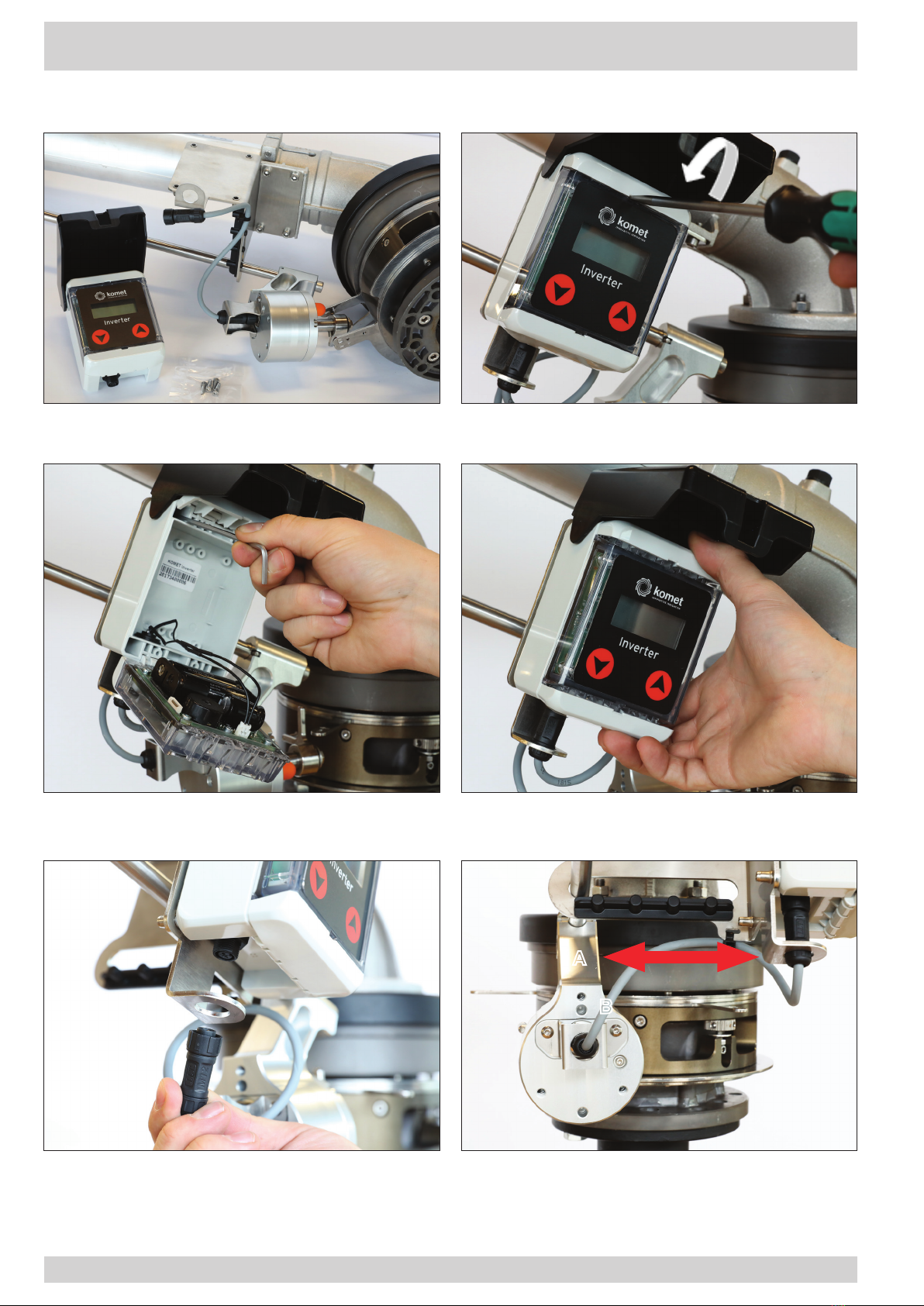
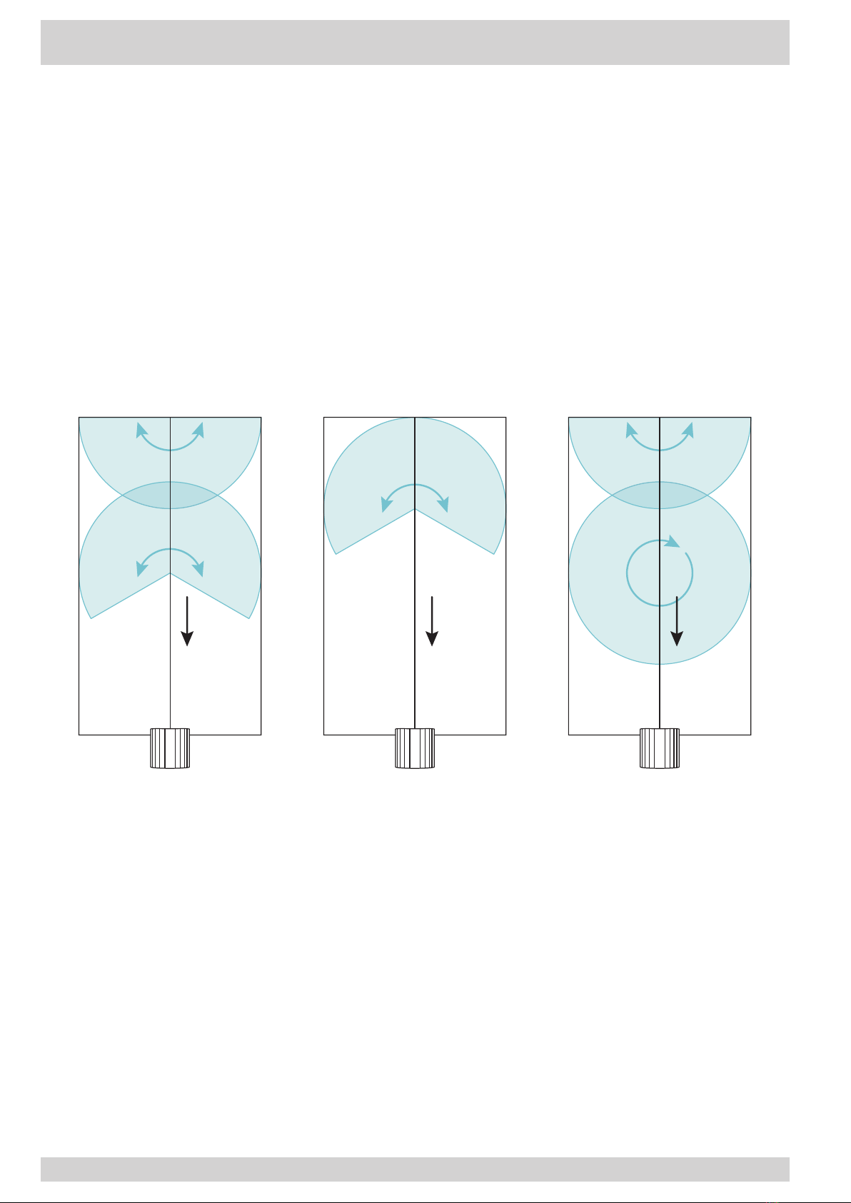
Set-up of the Inverter for Application "A" (Initial Inversion)
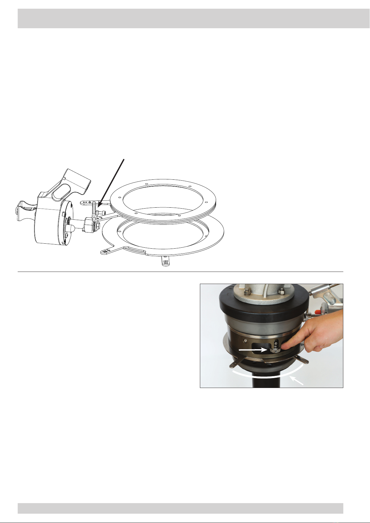
Lock Nut
Sector Angle 2
2. Set Sector 2
• To set sector 2 (second angle) loosen the lower lock nut.
The sector rings 2 are now released and can be
brought into the desired position for sector 2.
• Tighten the lock nut by hand.
• Control that sector rings 1 and 2 are effectively locked
by trying to move them.
1. Set Sector 1
• To set sector 1 (first angle) loosen the upper lock
nut. The sector rings 1 are now released and can be
brought into the desired position.
ATTENTION! The set sector angle is always lying
in between the arrows pointing to each other.
• Make sure, that the inverter fork is positioned IN
BETWEEN the arrows of the sector rings 1, pointing
to each other.
• After the desired angle has been set, tighten the lock
nut by hand (without tools).
• If the inverter fork in its basic position (see positions
page 9) is located outside of sector 1, turn the inverter
fork forcefully clockwise until it can be moved below
the arrow of sector ring 1. As soon as the inverter fork
is positioned in between the arrows of sector rings 1
pointing to each other, bring the inverter fork into its
initial basic position by turning it anti-clockwise.
ATTENTION! The inverter fork must be turned
back to its defined position until it clicks into
place. Control whether the inverter fork is effectively
locked by trying with minimal force to remove it. If
effectively locked it must stay in place.
The Inverter fork is positioned
in between the arrows of the sector rings 1,
pointing to each other