Komfovent DOMEKT series Manual
DOMEKT
INSTALLATION
AND SERVICE
MANUAL
EN

UAB KOMFOVENT we reserve the right to make changes without prior notice
D_21-03 3
Thissymbolindicatesthatthisproductisnottobedisposedofwithyourhouseholdwaste,accordingtothe
WEEEDirective(2002/96/EC)andyournationallaw.Thisproductshouldbehandedovertoadesignated
collection point, or to an authorised collection site for recycling waste electrical and electronic
equipment (EEE). Improper handling of this type of waste could have a possible negative impact
on the environment and human health due to potentially hazardous substances that are generally
associated with EEE. At the same time, your cooperation in the correct disposal of this product will
contribute to the eective usage of natural resources. For more information about where you can
drop o your waste equipment for recycling, please contact your local city oce, waste authority,
approved WEEE scheme or your household waste disposal service.
Content
1. SAFETY REQUIREMENTS..................................................................................................................................................4
2. TRANSPORTATION ..............................................................................................................................................................4
3. BRIEF DESCRIPTION OF THE UNIT..............................................................................................................................5
4. INSTALLATION .....................................................................................................................................................................12
4.1. Duct system installation..............................................................................................................................................15
4.2. Condensate Drain Connections...............................................................................................................................17
4.1.1. Water trap installation for a unit section mounted on the suction side.......................................18
4.1.2. Water trap installation for a unit section mounted on the pressure side....................................18
4.3. Heating coil connection..............................................................................................................................................24
4.4. Final Inspection..............................................................................................................................................................24
5. MAINTENANCE.................................................................................................................................................................... 25
6. UNIT DIMENSIONS.............................................................................................................................................................27
6.1. Vertical units ....................................................................................................................................................................27
6.2. Horizontal units............................................................................................................................................................. 28
6.3. Flat units........................................................................................................................................................................... 29
6.4. Filters................................................................................................................................................................................. 30
EN
UAB KOMFOVENT we reserve the right to make changes without prior notice
D_21-03
4
1. SAFETY REQUIREMENTS
• To avoid accidents and/or unit damage, only a trained technician must carry out
the connection.
• The appropriate Personal Protective Equipment (PPE) attire is worn relative to the
operation being carried out.
• Electrical equipment is rated, connected and earthed in accordance with CE regu-
lations.
The air handling unit must be plugged in to an electrical outlet (with earth), which is in good order
and corresponds with all requirements of electric safety. Before starting any operations inside the unit,
make sure that the unit is switched o, and the power cable is unplugged.
• Earth must be installed according EN61557, BS 7671.
• The unit should be installed according to Installation and Maintenance Manual.
• Before starting the unit, check correct position of air lters.
• Service maintenance should be carried out only in conformity with the
instructions specied herein below.
• If main cable is damaged, only manufacturer, service team or trained technician
must change it in order to avoid accidents.
• Drilling and using self-tapping screws on the unit casing is prohibited (where it is
not provided by the construction), since cables or tubes inside of the casing may
be damaged.
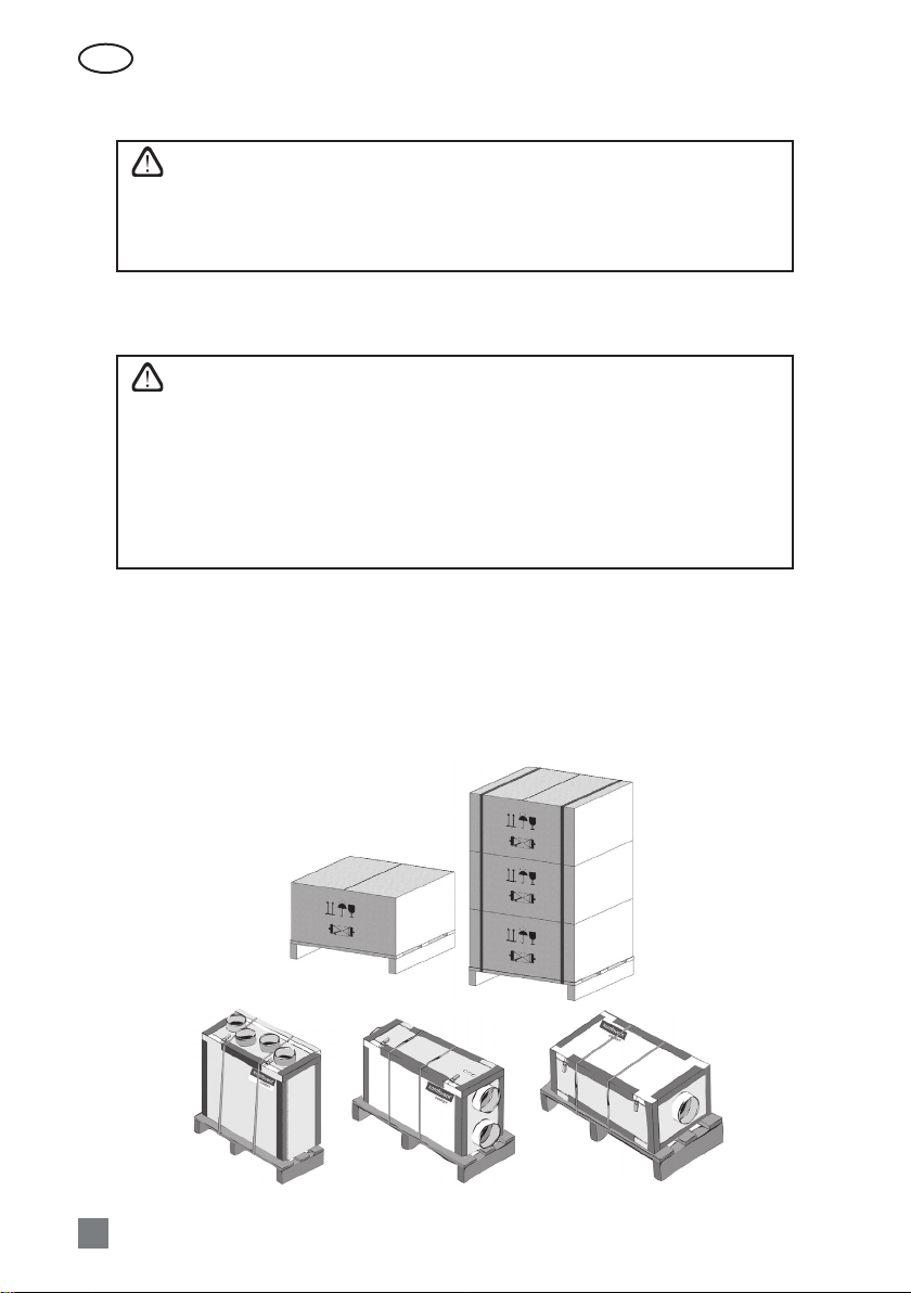
2. TRANSPORTATION
The air handling units are ready for transit and storage (1 Picture). The unit is packed to prevent dam-
age of the external and internal parts of the unit, dust and moisture penetration.
Corners of the air handling units are protected against the damage – protective corners are used.
The entire unit is wrapped up in protective lm. For transit or storage, units are mounted on timber pal-
lets. The unit is fastened to the pallet with polypropylene packing tape over protective corners.
Vertical and horizontal units ready for transit and storage
1 Picture
UAB KOMFOVENT we reserve the right to make changes without prior notice
D_21-03 5
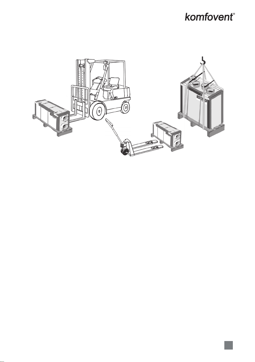
When unit is loaded or unloaded by crane, cargo rope is fastened in its designated places.
Forklift truck or hand pallet truck can transport air handling unit as it is shown (2 a, b, c Pictures).
Vertical and horizontal unit transportation by forklift truck, hand pallet truck or crane
2a Picture
2c Picture
2b Picture
2a Unit is transported by forklift truck on a wooden pallet;
2b Unit is transported by hand pallet truck on a wooden pallet;
2c Unit is lifted by crane on a wooden pallet.
The unit should be examined upon receipt, to ensure that no visible damage has occurred during
transit, and the advice note checked to ensure that all items have been received. If damage or delivery
shortages are discovered, the carrier should be immediately informed. KOMFOVENT should be notied
within three days of receipt, with a written conrmation sent within seven days. KOMFOVENT can accept
no responsibility for damage by unloading from carrier or for subsequent damage on site.
If the unit is not to be installed immediately, it should be stored in a clean, dry area. If stored exter-
nally, it should be adequately protected from the weather.
3. BRIEF DESCRIPTION OF THE UNIT
• The air handling units are intended for ventilation of small and medium-sized spaces (eg. single
family houses, oces, etc.), having operating ambient temperature and relative humidity. The unit
is intended to be installed in the domestic or non residential premises. Mineral wool is used for
thermal insulation and sound attenuation. Units cover panels are 25–50 mm thick. As standard, the
unit is designed for indoor placement. In cold, wet rooms possible icing or condensation on the
housing inside and outside. The operating temperature range for the unit is -30 °C ... +40 °C, outdoor
air temperature. Extracted indoor air temperature +10 – +40°C, relative humidity (non-condensing)
20–80%.
• The air handling unit is not to be used to transport solid particles, even not in areas where there is a
risk of explosive gases.
• Inside of the air handling unit it is integrated heat-exchanger and heater (or cooler), which compen-
sates losses of the heat/cold during ventilation of the premises, thus AHU is not recommended to
be used as main heating/cooling source of the building. AHU may not reach the supply temperature
setpoint if the actual room temperature diers a lot from the desired value, since in that case heat
exchanger capacity will be low.
EN
UAB KOMFOVENT we reserve the right to make changes without prior notice
D_21-03
6
• Before you open the door, the unit must be switched o and the fans must have been given time to
stop (up to 3 minutes).
• The unit contains heating elements that must not be touched when they are hot.
• We recommend to leave air handling unit in working mode (minimum 20 percent of power) during
the rst operation year. Due to moisture in building constructions, condensation may occur inside
and outside the air handling unit. Continuous operation of the equipment will signicantly reduce
the risk of condensation.
• Under conditions, when the outdoor air temperature is low and humidity is high, risk of heat ex-
changer frosting may appear. For this reason anti-frost protection function is foreseen in the con-
troller of the Komfovent air handling units. Depending on the type of the air handling unit, dierent
methods of anti-frost protection are available: cold air by-passing, supply air fan speed reducing
and/or integrated preheater. Counter cross ow heat exchanger is the mostly sensitive for low out-
side air temperatures, as the risk of frosting appears in the temperature range from 0to -5 °C and be-
low. Standard aluminium cross-ow plate heat exchanger has better features, as the risk of freezing
appears only at -10°C. The lowest risk and the highest resistance to cold outside air is a competitive
feature of the rotary heat exchanger, as it is not freezing even at the temperatures of -30 °C if the
humidity level of the air is appropriate.
In the units with counter ow or cross ow plate exchangers without integrated
preheater, it is necessary to install additional duct mounted preheater in the out-
side air intake duct, which will ensure temperature of the intake air higher than
-4°C.
• Selecting the management without pre-heater, but with cold air bypass the unit must be addition-
ally equipped with a secondary duct mounted heater.
UAB KOMFOVENT we reserve the right to make changes without prior notice
D_21-03 7
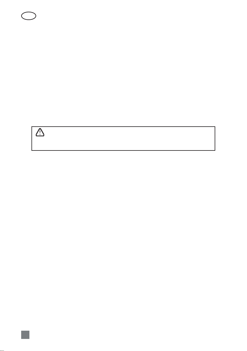
If the unit is mounted in premises with high humidity, condensation might occur on the surface of
the unit when outdoor temperatures are low (see picture 3). When installing unit in such a premises, it
is necessary to take additional measures, to avoid condensate damage to the building construction ele-
ments or furniture.
Relative humidity of the premises where the unit is mounted, %
80
75
70
65
60
55
50
45
40
35
30
25
20
12 14 16 18 20 22 24 26 28 30 32
Air temperature of the premises where the unit is mounted, °C
Outdoor air temperature, °C
10
5
0
-5
-10
-15
-20
-25
3 picture. Condensation on unit surface diagram
EN
UAB KOMFOVENT we reserve the right to make changes without prior notice
D_21-03
8
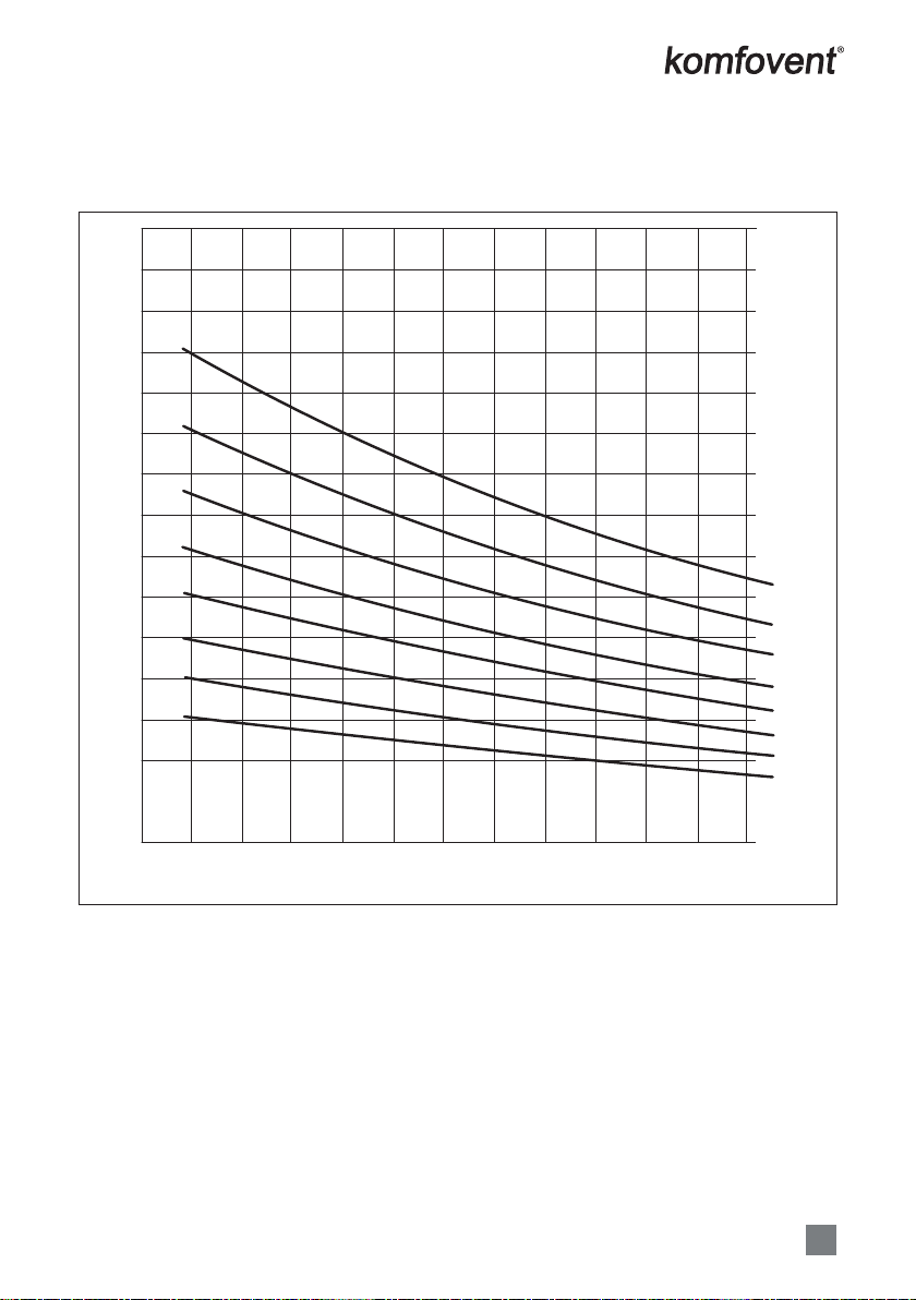
From the diagram in picture 3, it can be checked under what conditions condensate might appear
on the unit external surfaces.
Relative humidity of the premises where the unit is mounted, %
80
75
70
65
60
55
50
45
40
35
30
25
20
15
12 14 16 18 20 22 24 26 28 30 32
Air temperature of the premises where the unit is mounted, °C
Outdoor air temperature, °C
10
5
0
-5
-10
-15
-20
-25
123
To minimize possibility of condensation on unit outer surfaces use following recommendations:
1) Maintain lower relative humidity in the room where air handling unit is mounted;
2) Preheater should be installed to increase the supply air temperature.
It is recommended to keep air handling unit constantly running and in cases when
ventilation is not necessary, switch it to the minimum intensity (20%). In that way,
good indoor climate will be maintained and condensation inside of the unit will
decrease, avoiding humidity damage to electronic components.
Example No. 1
Temperature of the premises 20°C
Relative humidity of the premises 47%
Condensate will occur when outdoor
temperature is lower than +3°C
Example No. 2
Temperature of the premises 22°C
Outdoor temperature -5°C
Condensate will occur when relative
humidity of the premises will be higher
than 37%
Example No. 3
Relative humidity of the premises 40%
Outdoor temperature 0°C
Condensate will occur when tempera-
ture of the premises will be higher than
24,5°C
UAB KOMFOVENT we reserve the right to make changes without prior notice
D_21-03 9
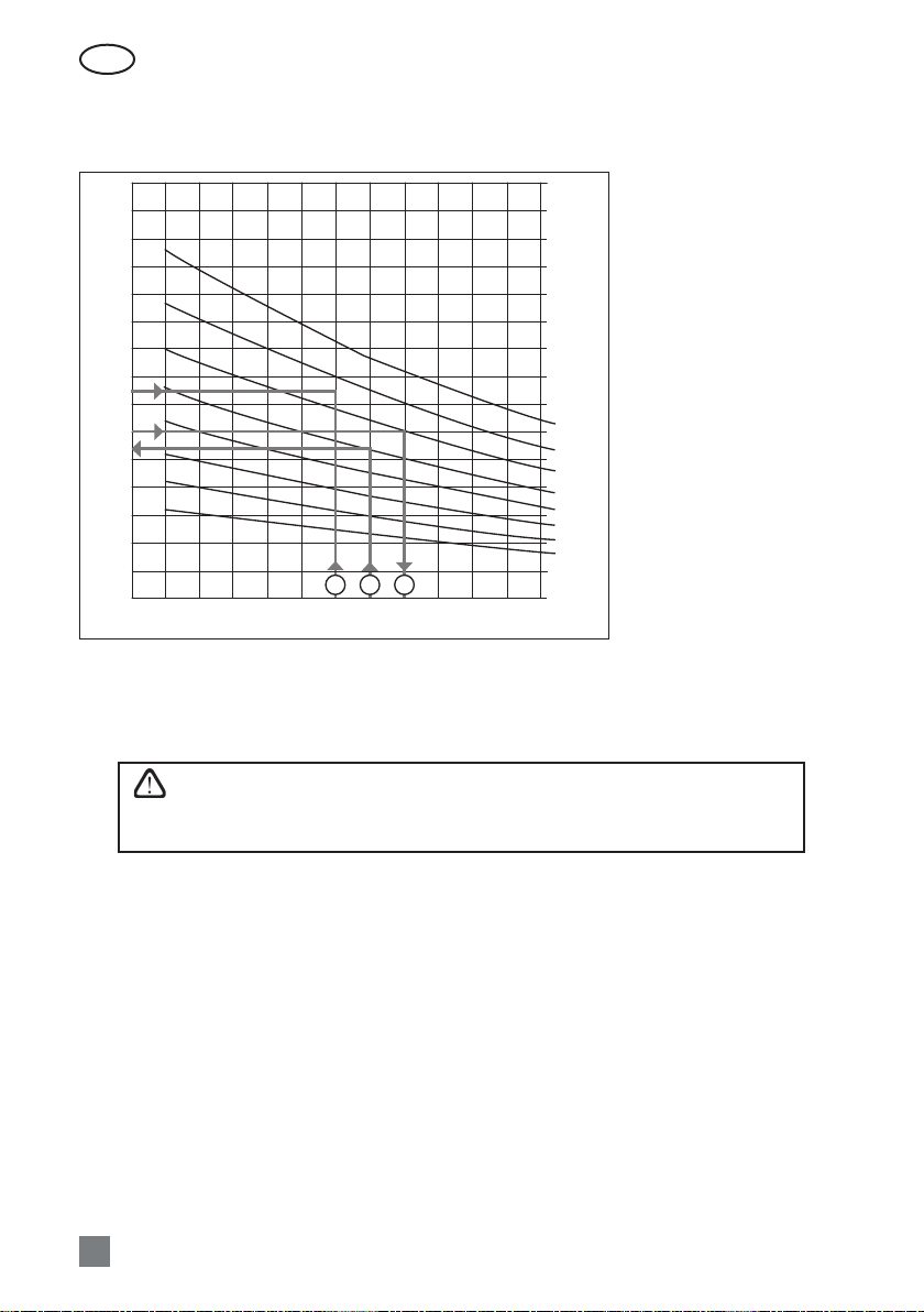
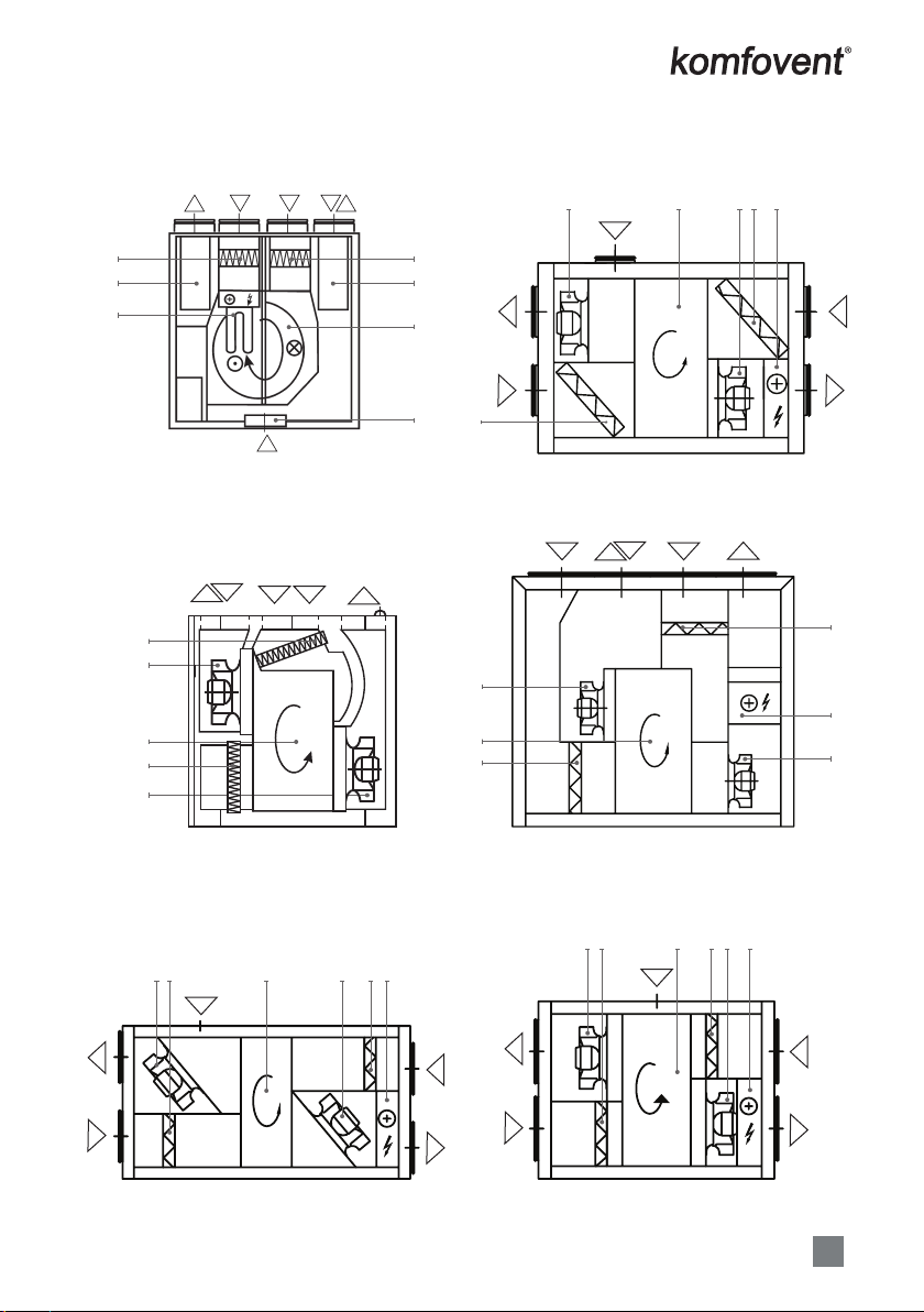
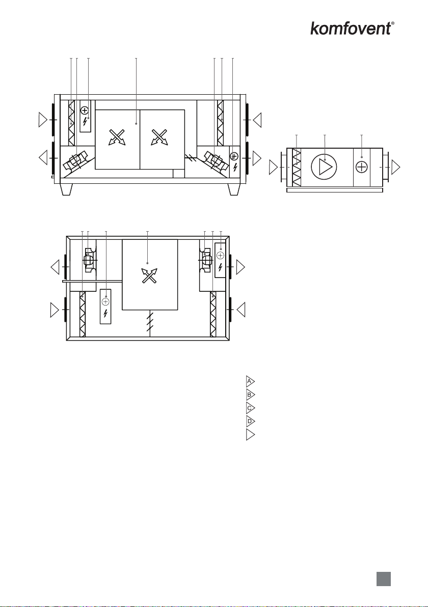
Air Handling Units Schemes
5
2
7
4
3
6
1
BA C E D
E
DOMEKT R 190V / 200V
6
3
1
5
4
C
BA E D
DOMEKT R 300V
E
D
A
C
B
3
4
15
62
DOMEKT R 250 F C6
B
E
ADC
2
5
4
3
6
1
DOMEKT R 500V** / DOMEKT R 700V**
D
A
E
C
B
63 1 45 2
DOMEKT R 600H
E
D
A
C
B
6 3 1 54 2
DOMEKT R 700H

EN
UAB KOMFOVENT we reserve the right to make changes without prior notice
D_21-03
10
ADCB
3
6
2
1
DOMEKT CF 400 V
D
A
B
C
1263 5
4
2
DOMEKT CF 250 F
A
D
C
B
1
263 5 24
DOMEKT CF 500 F
H
H
DACB
62 3 4 5 2
DOMEKT CF 700 V
C
BD
A
2 6 13 54
DOMEKT R 700F
C
B
A
D
E
6 3 1 5 4 2
DOMEKT R 400F
UAB KOMFOVENT we reserve the right to make changes without prior notice
D_21-03 11
B
C
D
A
1
263 5 24
DOMEKT CF 700 F
A
D
C
B
1
263 5 24
DOMEKT CF 700 H
3 5 2
AB
DOMEKT S 650 F / 800 F / 1000 F
A. Outdoor intake
B. Supply air
C. Extract indoor
D. Exhaust air
EE. Kitchen hood connection
(by-pass – extraction without heat recovery)
1. Rotary or plate heat exchanger
2. Electric or water air heater
3. Supply air lter
4. Exhaust air lter
5. Supply fan
6. Exhaust fan
7. Air by-pass damper
8. Condensate drain
(the water trap must be installed)

EN
UAB KOMFOVENT we reserve the right to make changes without prior notice
D_21-03
12
4. INSTALLATION
It is recommended to install the air handling unit in a separate room or in the attic on a hard smooth
surface insulated with a rubber mat. The minimum free space in front of the control panel should be not
less than 700mm. The free space over the top of the unit should be at least 300 mm (4 a, b Picture). Rub-
ber vibration absorbers must be used when unit is going to be mounted on the wall or ceiling.
The place for the unit must be selected with allowance for minimum access to the unit for mainte-
nance or service and must comply with safety requirements. Opening for inspection can not be smaller
than dimensions of the unit and unit itself must be mounted in a way, that if needed (for example in case
of complicated repair) it can be easily dismounted.
Minimum Maintenance Space
for Horizontal Units
100 mm
min. 700 mm
4a Picture
Minimum Maintenance Space
for Vertical Units
100 mm
min. 700 mm
4b Picture
Unit Installation Scheme
23
12
4 5
2
1
3
4
1. Air handling unit
2. Air duct connections
3. Sound attenuator
4. Drain siphon (if provided)
5. Rubber vibration absorber (not included in unit set)
4 Picture

UAB KOMFOVENT we reserve the right to make changes without prior notice
D_21-03 13
B
ceiling
A
min. 100 mm
5
B
1
Inspection
trapdoor
223
5a Picture*
2 21 3
5
A
A
D
C
B
B
5b Picture**
* Only F type units
** Only R 250 F, R 400 F, R 700 F, S 800 F HW, S 1000 F HW units.

EN
UAB KOMFOVENT we reserve the right to make changes without prior notice
D_21-03
14
DOMEKT CF 250F – CF 500F – CF 700F Units brackets’ positions
15
6 Picture
DOMEKT CF 400 V Unit brackets’ positions
520
750
838
867
598 600
260 39
7 Picture
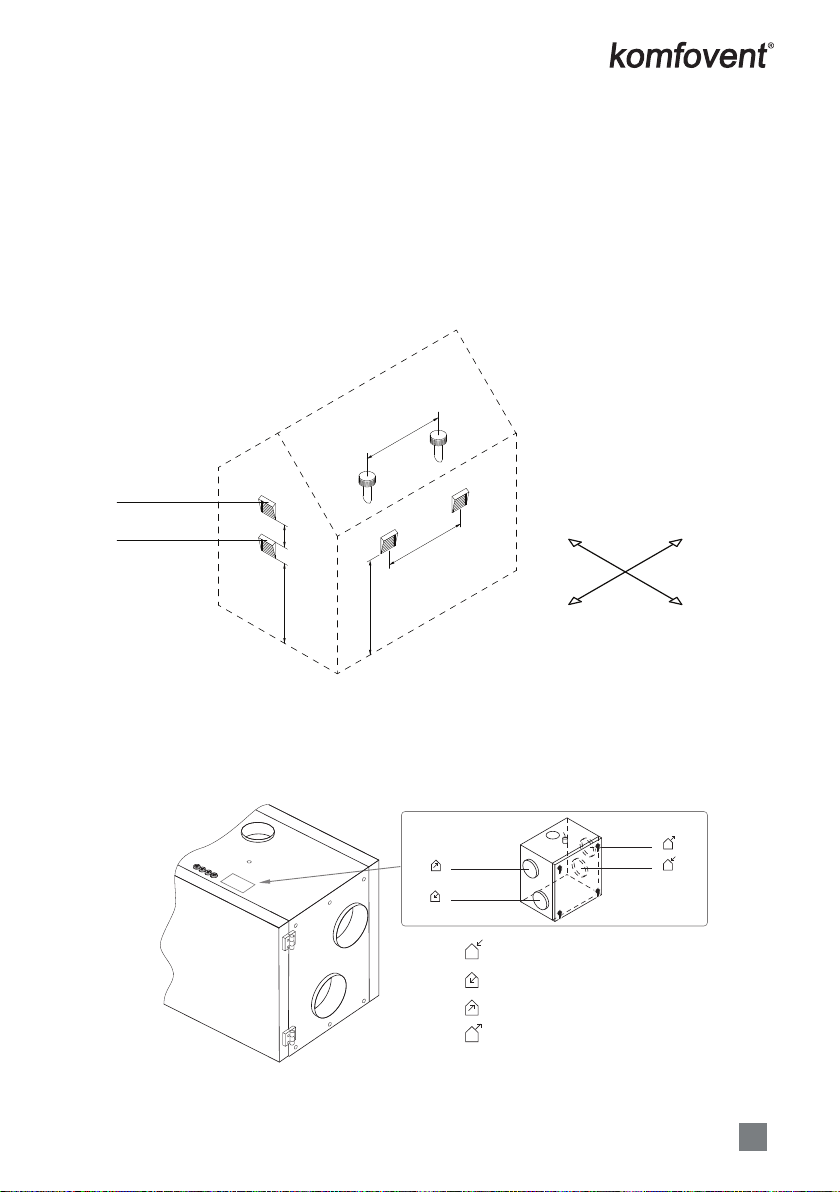
Pictures 7a and 7b show unit’s upper and bottom xing element.
2
3
4
5
6
9
1
8
2
7
1
7a Picture 7b Picture
1. Screw
2. Wall plug
3. Hanging bracket 1
4. Hanging bracket 2
5. Bolt M5
6. Gasket
7. Self tapping screw
8. L-shape bracket
9. Washer M5 DIN9021
UAB KOMFOVENT we reserve the right to make changes without prior notice
D_21-03 15
4.1. Duct system installation
The air in and out of the unit ows through the duct system. The duct system should be designed
and selected to have low airow rates and low pressure dierentials, ensuring more accurate airow
rates, lower energy consumption, lower noise levels and longer life of the unit.
Outdoor vents must be installed as far apart as possible on dierent sides of the building to prevent
the exhaust air from returning to the air intakes. Try to install the air intake vents where the outdoor air
is the cleanest: do not direct them towards the street, car park or outdoor replace. We also recommend
installing the air intake vent on the north or east side of the building, where the heat of the sun in sum-
mer will not have a signicant eect on the supply air temperature.
It is highly recommended to install unit connecting ducts of supply inlet and exhaust outlet with a
minimum slope on the outside of the premise, to avoid water owing into the unit in case of rain or snow.
S
EN
W
min. 1,8 m
min. 1 m
Air exhaust vent
Air intake vent
min. 1,8 m
min. 3 m
min. 3 m
It is recommended to insulate the ducts in unheated rooms (attic, basement) to avoid heat loss. It is
also recommended to insulate the supply air ducts if the unit is used for room cooling.
The air ducts are tted to the unit with self-tapping screws. Dierent air ow duct positions are
marked on the sticker located on the AHU:
outdoor intake air
air supplied to the premises
air extracted from the premises
outdoor exhaust air
AODA
BSUP
CETA
DEHA
D
A
C
B
EHA
ODA
ETA
SUP
E
Fig. 8. Air duct marking
EN
UAB KOMFOVENT we reserve the right to make changes without prior notice
D_21-03
16
Most units with a rotary heat exchanger also have a fth branch (labelled E) to connect an additional
exhaust duct (see „Air Handling Units Schemes“). The air ow through this opening is delivered directly
to the exhaust fan, bypassing the heat exchanger, therefore, you can connect ducts from the bathroom,
toilet or kitchen without worrying that odours and bacteria will contaminate the rotary heat exchanger
or be passed on to the supplied air ow. However, air is extracted through an additional branch without
recuperation, thus reducing the eciency of the heat exchanger. For this reason, we do not recommend
using the extra air extraction continuously. An additional exhaust duct should be tted with air closing
damper (motorized are recommended) and should only be opened when additional extraction is re-
quired (e.g. when bathing). If the additional branch is connected to the kitchen hood with an integrated
closing damper, an additional damper is not needed.
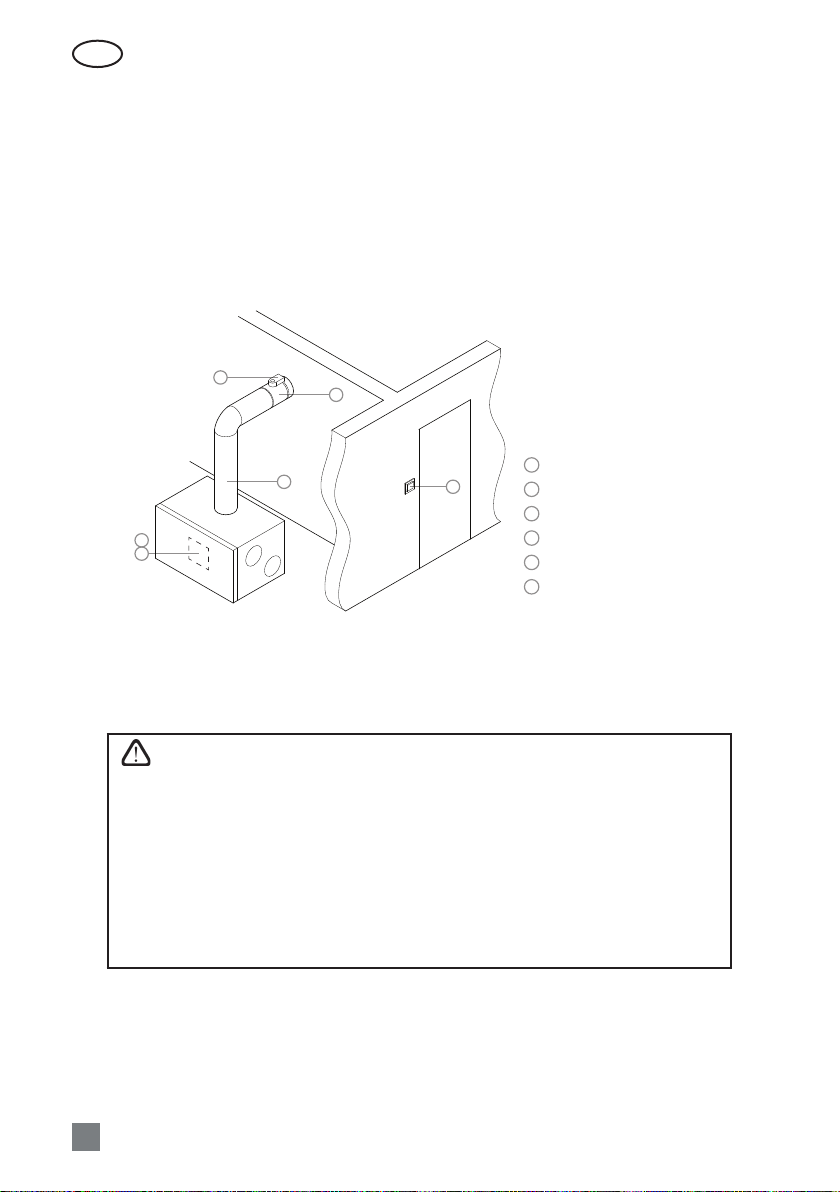
2
5
4
3
6
1
WC
1
2
3
4
5
6
Controller board
Switch
Spring return actuator with end position
contacts (e.g. Belimo LF-230S)
Air closing damper
Additional extraction duct
Air handling unit
Fig. 9. Example of mounting of an additional air extraction duct
Note: temperature sensor B1 has to be mounted in the supply air duct under electric heater (see the functional diagram in
Control System Electrical Installation and Operation Manual). It is necessary to leave space in straight air duct for sensor
mounting and guarantee the space for maintenance and service work. Minimal space between the unit and B1 sensor is the
space of double air duct diameter.
• Ducts connecting the unit to the exterior of the building must be insulated
(insulation thickness 50–100 mm) to prevent condensation on cold surfaces.
• Air intake and exhaust ducts must be tted with air closing dampers (mechan-
ical spring-loaded or electric with actuators) to protect the unit from exposure
to climatic conditions when the unit is switched o.
• In order to minimise AHU noise transferring through the ducts into ventilated
areas, sound attenuators must be connected to the unit.
• Duct system elements must have separate brackets and to be mounted in a
way that their weight is not shifted to the unit casing.
• The kitchen hood with integrated exhaust fan must not be connected to the
additional air exhaust duct. Such hood must be connected to a duct sepa-
rated from the general ventilation system.
UAB KOMFOVENT we reserve the right to make changes without prior notice
D_21-03 17
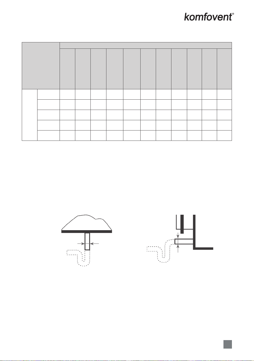
The diameter of the ducts varies by unit model:
Unit
Domekt R 190 V
Domekt R 200 V
Domekt R 300 V
Domekt R 250 F
Domekt R 400 F
Domekt R 600 H
Domekt R 700 H
Domekt R 500 V
Domekt R 700 V
Domekt R 700 F
Domekt CF 250 F
Domekt CF 400 V
Domekt CF 500 F
Domekt CF 700 V
Domekt CF 700 F
Domekt CF 700 H
Domekt S 650 F
Domekt S 800 F
Domekt S 1000 F
Duct diameter,
mm
Duct A 125 160 160 200 250 160 200 250 160 200 250
Duct B 125 160 160 200 250 160 200 250 160 200 250
Duct C 125 160 160 200 250 160 200 250 ---
Duct D 125 160 160 200 250 160 200 250 ---
Duct E 125 100 125 125 125 - - - - - -
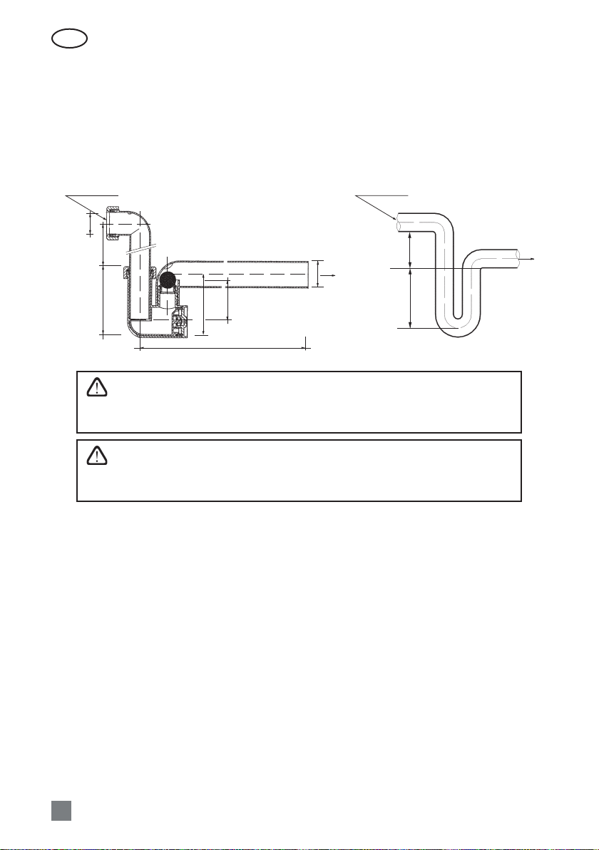
4.2. Condensate Drain Connections
All condensate drain connections must be correctly trapped. Incorrect trapping can result in ood-
ing within the unit and consequent ooding of the immediate area. Fill the drain trap with water before
starting up the unit.
All drain lines should be insulated where passing through any space where damage from condensa-
tion drip might occur. If the unit is installed in unheated premises the condensate pipe should be heat-
insulated and heated with heating cable.
A condensate pipe and a drain trap
Drain scheme of Vertical Unit
view 1
D = 15
10a Picture
Drain scheme of Horizontal Unit
D = 15
view 2
10b Picture
The bend of the water trap can be repositioned by turning it to the right or the left. The drain line
from the water trap must be arranged so that it will not damage adjacent unit sections or building ele-
ments. If the drain line is run through cold spaces, it should be insulated to prevent freezing. A heating
cable may be required.
EN
UAB KOMFOVENT we reserve the right to make changes without prior notice
D_21-03
18
4.1.1. Water trap installation for a unit section mounted on the suction side
Since the fans in most air handling units are last in the chain of functions and generate sub-atmos-
pheric pressure inside the unit,it is very important to correctly install the water trap. Because of that rea-
son condensate can be hardly eliminated from the air handling unit and the technical premise may get
covered with condensate. Height H1must be at least equivalent in mm to half of the negative pressure
inside the unit in mm water gauge. Height H2must be at least equivalent in mm to the negative pressure
inside the unit in mm water gauge.
Ø 32
25-240106
DN 40
95
H1, H2
140-310
Condensate Condensate
H2
H1
Precaution: The drainage siphon should be mounted on the outlet tting pipe
of every drip tray for complete condensate drainage from the air handling unit and
prevention of penetration of oensive odours from an euent into the ventilation
system.
In case of the outdoor operation of the air handling unit, the siphon and the bleed-
ers should be heated with an electric thermal cable (if ambient air temperature
tamb< 0 °C). The siphon and the bleeders should be heat-insulated with an insulat-
ing material.
4.1.2. Water trap installation for a unit section mounted on the pressure side
Since the fans in most air handling units are not last in the chain of functions and generate over-
atmospheric pressure inside the cooling section. In such case the consisted condensate can be easily
removed from AHU and there will be no strict requirements for siphon‘s installation. A drainage siphon
is enough with a minimum rake.
RECOMMENDATION: The drainage siphon must be installed in connection with not less size pipe
diameter.
Any drainage systems must not be connected directly to the municipal sewage system. The conden-
sate tray shall be easily accessible for cleaning and disinfection.
UAB KOMFOVENT we reserve the right to make changes without prior notice
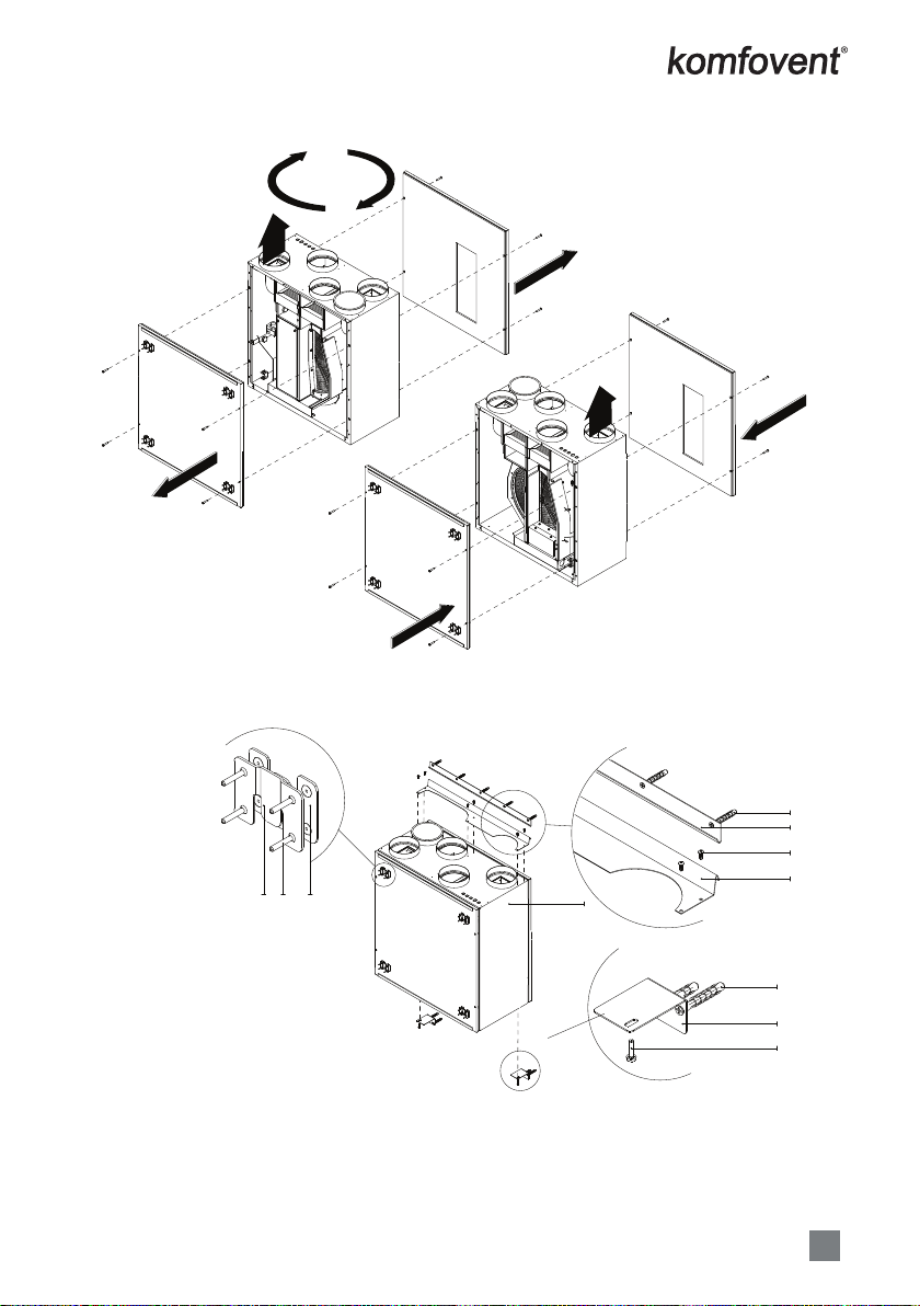
D_21-03 19
DOMEKT R 190V / 200V unit inspection side change
1
2
3
4
5
8 9 8
5
6
7
SUP
SUP
SUP – Supply air duct connection.
DOMEKT R 190V / 200V Unit hanging scheme without kitchen hood
1
2
3
4
5
8 9 8
5
6
7
SUP
SUP
1. Air handling unit DOMEKT R 190V / 200V
2. Wall plug 8×50 + screw 4,5×50
3. Wall mounting bracket
4. Self tapping screw 4,2×13
5. Unit bracket
6. Bottom bracket
7. Screw M4x16 (DIN 7895)
8. Bracket for decorative panel
9. Screw 2.5×16 with cone head
EN
UAB KOMFOVENT we reserve the right to make changes without prior notice
D_21-03
20
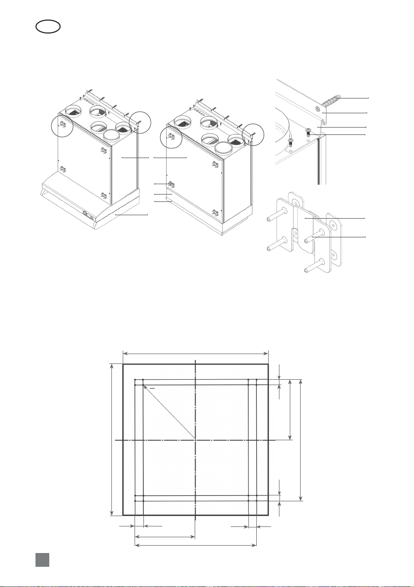
DOMEKT R 190V / 200V unit with kitchen hood
Air handling unit DOMEKT R 190V / 200V can be mounted with one of the two types of kitchen hoods
(11, 12 Picture).
1
9
2
3
4
BA
A
B
A
5
6
7
8
B
9
10
11 Picture
Dimensions for mounting furniture panel
22
625
600
500
250
22
32.5
500
250
32.5
Ø 2(depth – 5 mm) 16 holes
1. Air handling unit DOMEKT R 190V / 200V
2. Kitchen hood adapter 392-12
3. Kitchen hood 392-12
4. Standard kitchen hood
5. Wall plug 8×50 + screw 4,5×50
6. Wall mounting bracket
7. Unit bracket
8. Self tapping screw 4,2×13
9. Bracket for decorative panel
10. Screw 2.5×16 with cone head
Other manuals for DOMEKT series
4
This manual suits for next models
19
Table of contents
Other Komfovent Industrial Equipment manuals


Popular Industrial Equipment manuals by other brands


Festo
Festo CRDSNU Series operating instructions

Sense
Sense SNS t Series Quick user guide

Sterlitech
Sterlitech CF047 CELL Assembly & operation manual

SAMES KREMLIN
SAMES KREMLIN REGULEX 5 CC Installation and safety instructions

Siemens
Siemens 3VT9300-8LA00 operating instructions

GMP
GMP 89004 operation & maintenance


