Komfovent PPU-LCHX User manual

Pipework package unit for liquid coupled heat exchanger
PPU-LCHX

2UAB KOMFOVENT we reserve the right to make changes without prior notice
PPU-LCHX_21-05
EN
CONTENT
1. INTRODUCTION ...........................................................................................................................................................................................................3
2. ENCODING AND CONSTRUCTION ......................................................................................................................................................................3
3. MECHANICAL INSTALLATION...............................................................................................................................................................................4
4. ELECTRICAL INSTALLATION..................................................................................................................................................................................5
5. FLOW RATE REGULATION .......................................................................................................................................................................................7
6. PERIODICAL MAINTENANCE..............................................................................................................................................................................10
7. TECHNICAL DATA .....................................................................................................................................................................................................10
3
UAB KOMFOVENT we reserve the right to make changes without prior notice
PPU-LCHX_21-05
1. INTRODUCTION
This manual is intended for qualied technicians installing pipework package unit (PPU) for liquid coupled heat exchanger.
Qualied professionals are persons with sucient professional experience and knowledge of plumbing systems for heating/
cooling, their installation, knowledge of electrical safety requirements and ability to work without risk to themselves or others.
To avoid misunderstandings, read this manual carefully before installing the PPU, since ignoring the instructions not only
shall invalidate the manufacturer’s warranty but can also cause direct damage to property or human health.
• When performing installation works, make sure the frequency inverter and circulation pump are
unplugged from electrical supply. Do not connect them to electrical power until all mechanical
works on PPU are nished.
• Use caution when working near internal or external heaters of the airhandling unit (AHU), as
their surfaces may be hot.
• Do not connect frequency inverter and circulation pump to the power supply network if there is
visible damage that occurred during transportation.
• Use appropriate personal protective equipment (gloves, goggles) when installing or repairing
• the PPU.
This sign means that the product may not be disposed of together with your household waste as dened in Directive
(2002/96/EC) and national legislation on the management of WEEE. This product must be disposed of at an appropri-
ate collection point or recycling facility for waste electrical and electronic equipment (WEEE). Improper handling of
this type of waste due to hazardous substances inside electrical and electronic equipment can endanger the environ-
ment and human health. By helping to ensure proper disposal of this product, you will also contribute to the ecient
use of natural resources. For more information on how to dispose of such waste for further recycling, contact your city
authorities, waste management organisations, approved WEEE systems or your household waste management bodies
representatives.
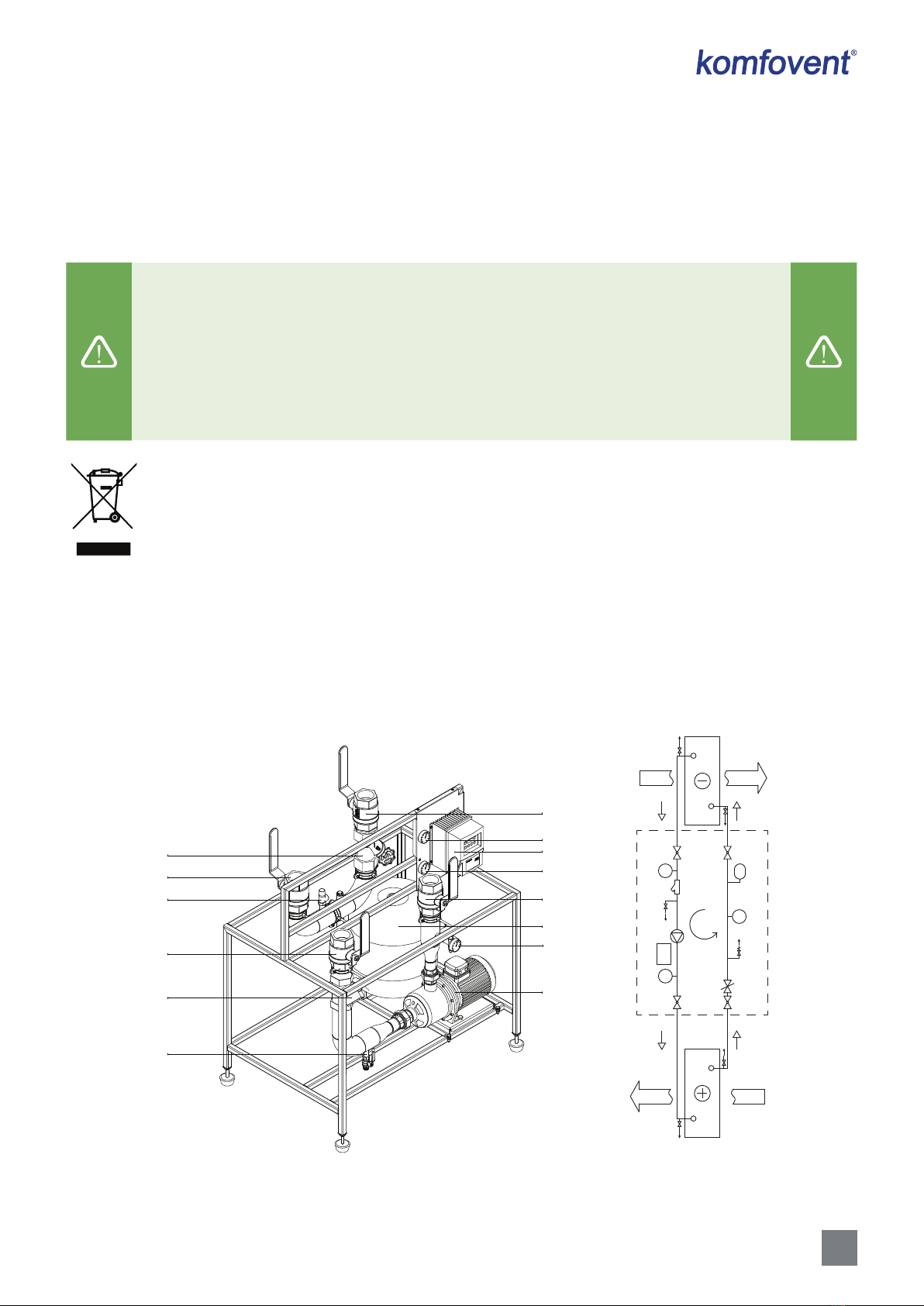
2. ENCODING AND CONSTRUCTION
PPU-LCHX is a pipework package unit for liquid coupled heat exchangers that are used for heat/cold recovery in the air
handling units (AHU). PPU ensures proper circulation of thermal medium (usually mixture of glycol and water) throughout
the piping circuit, regulates requperation eciency and prevents coils from freezing.
1
3
4
6
3
4
2
10
5
4
12
8
4
9
T
T
FC
P
1
3
4
6
3
4
2
10
5
4
12
7
11
8
4
9
Fig. 1. PPU components and hydraulic diagram
1 – Circulation pump; 2 – Frequency inverter; 3 – Thermometer; 4 – Ball valve; 5 – Water lter; 6 – Expansion vessel; 7 – Coil in the supply
airow; 8 – Safety valve; 9 – Drain valve; 10 – Manometer; 11 – Coil in the extract airow; 12 – Balancing valve

4UAB KOMFOVENT we reserve the right to make changes without prior notice
PPU-LCHX_21-05
EN
Encoding:
PPU - LCHX - FQ - L/R - 40 - WG2
123456
1. PPU – Pipework package unit
2. LCHX – Liquid coupled heat exchanger
3. FQ – with frequency inverter
4. L/R – suitable for right (R) and left (L) inspection side AHU’s
5. Connection pipe diameter (DN)
6. Type of circulation pump
3. MECHANICAL INSTALLATION
PPU-LCHX to be installed in technical room, where ambient temperature is 0..+40°C. Unit must be mounted on a at and
sturdy base or on a construction specially designed for mounting. If mounting base ins not at, PPU can be leveled using
adjustable feet at the bottom of the frame.
When selecting mounting location, you must foresee sucient and secure access space for repair
and maintenance operations. Also make sure PPU is not blocking access to the AHU and it’s door can
open freely.
Connect PPU to the heat exchanger coils of the AHU, following hydraulic diagram (see Fig. 1). It is important to ensure
that uid ow direction (marked on the arrow stickers of the PPU) is correct. For eective operation of liquid coupled heat ex-
changer, thermal medium ow direction should be against airow direction. When fully assembled, all hydraulic circuit must
be lled with glycol (not more than 40%) and water mixture. Pipes are lled through the drain valve until static pressure of
1.5bar is reached. Do not use circulation pump of the PPU for lling the pipes – additional equipment or pump must be used.
All piping between PPU and AHU coils should be thermally insulated after the works.

5
UAB KOMFOVENT we reserve the right to make changes without prior notice
PPU-LCHX_21-05
4. ELECTRICAL INSTALLATION
Electrical work may only be carried out by a qualied electrician in accordance with the instructions given in this manual
and in accordance with applicable legal requirements and safety requirements. Before performing electrical component
installation:
• Check there is no mechanical damage on frequency inverter or circulation pump.
• Check the insulation of the cable between frequency inverter and circulation pump is not
damaged.
• Locate user manual for the frequency inverter.
• If the PPU has been standing in an unheated room for a long time, make sure that electronic
parts and cable connectors were not aected by moisture.
Congure micro-switches, connect electrical power and control calbles to the frequency inverter (see Fig. 2):
DIN
10V
AIN
GND
A
B
A
B
COM
NC
U V W PE
PE L1 L2 L3
1
2 3
4
5
OFF ON
1
2
3
5
7
4
6
Fig 2. Frequency inverter
1 – Frequency inverter control terminals, 2 – Pump connection terminals, 3 – Main power terminals
4 – Micro switch conguration, 5 – Control panel connection (RJ9)
6UAB KOMFOVENT we reserve the right to make changes without prior notice
PPU-LCHX_21-05
EN
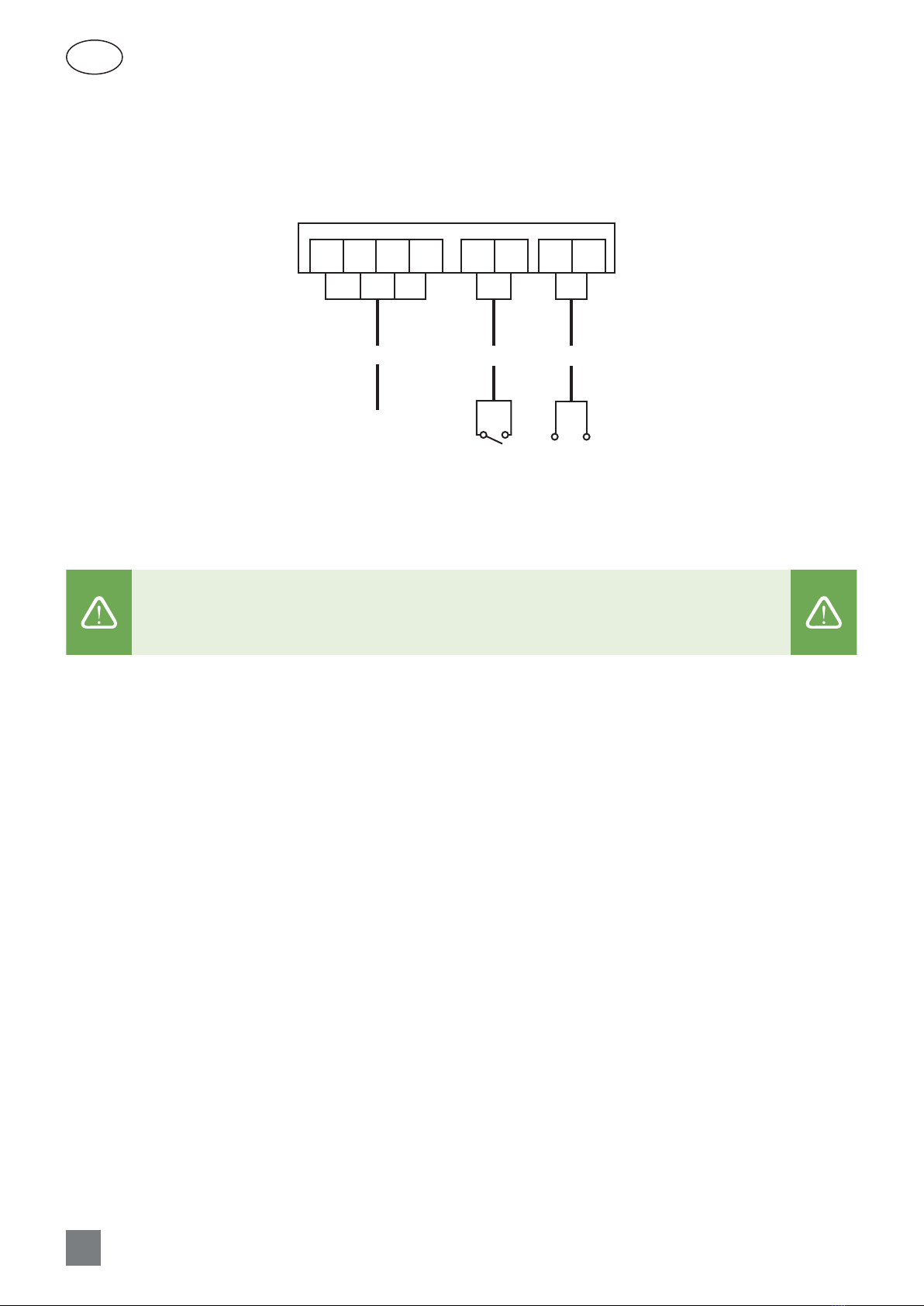
• Terminals L1, L2, L3, PE are for 3x400 V AC, 50 Hz electrical power connection. Connect power cable to the mains via 10A
automatic circuit breaker (type C).
• Terminals DIN and 10V are for inverter start/stop signal (open/close contact). If such signal is not needed, wire link must
be installed instead.
• Terminals AIN and GND is for inverter control signal (0..10V).
L1 DIN 10V AIN
0..10V DC
GND
COM
3x400V AC
L2 L3 PE
2x0,5mm 2x0,5mm4x1,5mm
Fig. 3. Frequency inverter connection diagram
• Connect the frequency inverter only to suitable power socket with appropriate earthing and
meeting the electrical safety requirements.
• For information on how to connect frequency converter to the AHU automation control, please
follow electrical wiring diagram of the AHU.

7
UAB KOMFOVENT we reserve the right to make changes without prior notice
PPU-LCHX_21-05
5. FLOW RATE REGULATION
For circulation pump to run correctly, it is needed to set PPU ow rate according to designed ow rate stated in the tech-
nical printout of the liquid coupled heat exchanger. Flow rate of the PPU is set as follows:
1. Fully open balancing valve.
2. Connect dierential pressure measuring equipment to the pressure measuring ports of the balancing valve.
3. Using ow rate diagram (Fig. 4), determine which dierential pressure should be achieved, for PPU to reach the de-
signed ow rate.
pressure drop
0,05
0,01
0,01 0,1 1 10 100
100
kv
qmow rate
0,5
5
50
0,05 0,5 5 50
50000
500050050
[dm3/h]
[kPa]
Δp
0,1
10
1
10 100 1000 10000 100000
DN25
DN32
DN40 DN50 DN65
DN20
Fig. 4. Flow rate diagram of the balancing valves
4. Connect control panel of frequency inverter (see Fig. 2).
It is mandatory to turn OFF main power of the inverter, when connecting or disconnecting control
panel cable, otherwise panel will be damaged.
5. Turn ON power of the inverter. Set initial frequency using control panel (20 Hz recommended) and start the inverter:
Output setpoint control, Hz
020.0
1
4
7
2
5
8
0
3
6
9
[1] Operation mode c...
1 - Run
2 - Fire mode
0 - Stop
[1] Operation mode c...
0 - Stop
1 - Run
9 - Analog control
0.0 Hz
Output setp.
0 - Stop
Output freq.
0.0 Hz
Page 1
16:30
0.0 Hz
Output setp.
0 - Stop
Output freq.
0.0 Hz
Page 1
16:30

8UAB KOMFOVENT we reserve the right to make changes without prior notice
PPU-LCHX_21-05
EN
6. By increasing/decreasing inverter frequency, regulate pump speed until correct dierential pressure will be reached.
Memorize or write down operating frequency of the inverter at this pressure point.
20.0 Hz
Output setp.
1 - Run
Output freq.
20.0 Hz
Page 1
16:30
Output setpoint control, Hz
030.0
1
4
7
2
5
8
0
3
6
9
?
7. Stop the inverter:
30.0 Hz
Output setp.
1 - Run
Output freq.
30.0 Hz
Page 1
16:30
[1] Operation mode c...
1 - Run
2 - Fire mode
0 - Stop
[1] Operation mode c...
0 - Stop
1 - Run
9 - Analog control
8. Enter to the parameter 102 same frequency, under which correct dierential pressure was reached (according step 6).
Configuration Op. settings
Overview Motor
Menu
Operation settings
1/ 6
[100] Drive current
limit, %
100 %
[101] Minimum output
freq., Hz
4.0 Hz
[102] Maximum output
freq., Hz
80.0 Hz
[103] Skip frequency 1,
Hz
0.0 Hz
[102] maximum output freq...
030.0
1
4
7
2
5
8
0
3
6
9
0.0 Hz
Output setp.
0 - Stop
Output freq.
0.0 Hz
Page 1
16:30
?

9
UAB KOMFOVENT we reserve the right to make changes without prior notice
PPU-LCHX_21-05
9. Enter to the parameter 306 same frequency, under which correct dierential pressure was reached (according step 6).
Configuration
1/ 4
[300] Modbus ID
60
[301] Modbus baud rate
7 - 57600 baud
[302] Modbus data
format
2 - 8E1
[303] Output setpoint
type
0 - Frequency, Hz
Configuration
2 / 4
[304] Modbus control
timeout, sec
10.0 s
[305] AIN lowest level
frequency, Hz
2.0 Hz
[306] AIN highest level
frequency, Hz
80.0 Hz
[307] AIN lowest level, %
5.00 %
[306] AIN highest level fre...
030.0
1
4
7
2
5
8
0
3
6
9
Configuration Op. settings
Overview Motor
Menu
0.0 Hz
Output setp.
0 - Stop
Output freq.
0.0 Hz
Page 1
16:30
?
10. Turn OFF power of the inverter. If control panel will not be used, disconnect it from the inverter. Also disconnect con-
trol panel in case if PPU is mounted in the unheated room..
It is mandatory to turn OFF main power of the inverter, when connecting or disconnecting control
panel cable, otherwise panel will be damaged.
11. Turn ON main power of the inverter and start AHU. Check operation of the liquid coupled heat exchanger and
PPU-LCHX.

10 UAB KOMFOVENT we reserve the right to make changes without prior notice
PPU-LCHX_21-05
EN
6. PERIODICAL MAINTENANCE
• Before starting any maintenance works, make sure that PPU and AHU are stopped.
• If there is a need to perform any mechanical works on the piping circuit (for example to tighten
couplings or to clean water lter and etc.) disconnect PPU and AHU from the mains power.
It is recommended to carry out PPU-LCHX periodical maintenance at least once a year. If needed register performed
works in the maintenance log.
Following to be checked during maintenance:
• Piping circuit is tight, there are no leakage marks.
• Circulation pump operates correctly. There are no big vibrations or unnecessary noise.
• There are no alarms on the frequency inverter.
• Signal and power cables are in good condition, there are no corrosion marks on the connectors and electrical terminals.
• Measuring tools (manometer, thermometers) operates correctly.
• Water lter is not clogged (clean the lter if necessary).
7. TECHNICAL DATA
Pipework package unit
model
Filter and
balancing
valve
Pipe
connections Pump
type
Pump
power
Frequency inverter
Dimensions of the
PPU frame
(excluding
adjustable feet)
Expansion
vessel
volume
PPU
weight
DN inch kW B,
mm
H,
mm
L,
mm Liters kg
PPU-LCHX-FQ-L/R-20-WG1 DN20 20 3/4” WG1 0,55 DF2-551M0 500 867,5 650 5 45
PPU-LCHX-FQ-L/R-20-WG2 DN20 20 3/4” WG2 0,55 DF2-551M0 500 867,5 650 5 42
PPU-LCHX-FQ-L/R-25-WG1 DN25 25 1” WG1 0,55 DF2-551M0 500 867,5 650 8 46
PPU-LCHX-FQ-L/R-25-WG2 DN25 25 1” WG2 0,55 DF2-551M0 500 867,5 650 8 43
PPU-LCHX-FQ-L/R-32-WG2 DN32 32 1 1/4” WG2 0,55 DF2-551M0 550 867,5 700 12 47
PPU-LCHX-FQ-L/R-40-WG2 DN40 40 1 1/2” WG2 0,55 DF2-551M0 550 1037,5 850 18 60
PPU-LCHX-FQ-L/R-40-WG3 DN40 40 1 1/2” WG3 1,1 DF2-112M0 550 1037,5 850 18 65
PPU-LCHX-FQ-L/R-50-WG3 DN50 50 2” WG3 1,1 DF2-112M0 550 1037,5 900 24 71
PPU-LCHX-FQ-L/R-50-WG4 DN50 50 2” WG4 2,2 DF2-222S0 550 1037,5 900 24 78
PPU-LCHX-FQ-L/R-65-WG3 DN65 65 2 1/2” WG3 1,1 DF2-112M0 670 1037,5 1000 30 75
PPU-LCHX-FQ-L/R-65-WG4 DN65 65 2 1/2” WG4 2,2 DF2-222S0 670 1037,5 1000 30 82

11
UAB KOMFOVENT we reserve the right to make changes without prior notice
PPU-LCHX_21-05
DN20-DN32
BL
42-92
867,5
867,5
DN40-DN65
B L
42-92
1037,5
1037,5

PPU-LCHX_21-05
GERMANY
Komfovent GmbH
Konrad-Zuse-Str. 2a,
42551 Velbert, Deutschland
Tel. +49 0 2051 6051180
info@komfovent.de
www.komfovent.de
LITHUANIA
UAB KOMFOVENT
TECHNINĖS PRIEŽIŪROS SKYRIUS /
SERVICE AND SUPPORT
Phone: +370 5 200 8000
Email: service@komfovent.com
www.komfovent.com
RUSSIA
ООО «КОМФОВЕНТ»
Ул. Выборгская д. 16, стр. 1,
2 этаж, 206 офис, Москва, Россия
Тел. +7 499 673 22 73
www.komfovent.ru
ООО «КОМФОВЕНТ»
Ряжское шоссе, 20 литера Е, пом Н6
390017 г. Рязань, Россия
Тел.: +7 491 255 95 71
www.komfovent.ru
BELARUS
ИООО «Комфовент»
ул. Уручская 21 – 423,
220125 г. Минск, Беларусь
Тел. +375 17 266 5297, 266 6327
www.komfovent.by
SWEDEN
Komfovent AB
Ögärdesvägen 12B
433 30 Partille, Sverige
Tel. +46 31 487 752
info_[email protected]
www.komfovent.se
FINLAND
Komfovent Oy
Muuntotie 1 C1
FI-01 510 Vantaa, Finland
Tel. +358 0 408 263 500
info_@komfovent.com
www.komfovent.com
LATVIA
SIA Komfovent
Bukaišu iela 1, LV-1004 Riga, Latvia
Tel. +371 24 66 4433
info@komfovent.lv
www.komfovent.lv
Vidzemes liāle
Alejas iela 12A, LV-4219 Valmiermuiža,
Valmieras pagasts, Burtnieku novads
Tel. +371 29 358 145
kristaps.[email protected]
www.komfovent.lv
PARTNERS
AT J. PICHLER Gesellschaft m. b. H. www.pichlerluft.at
BE Ventilair group www.ventilairgroup.com
ACB Airconditioning www.acbairco.be
CZ REKUVENT s.r.o. www.rekuvent.cz
CH
WESCO AG www.wesco.ch
SUDCLIMATAIR SA www.sudclimatair.ch
CLIMAIR GmbH www.climair.ch
DK Øland A/S www.oeland.dk
EE BVT Partners www.bvtpartners.ee
FR ATIB www.atib.fr
HR Microclima www.microclima.hr
HU
AIRVENT Légtechnikai Zrt. www.airvent.hu
Gevent Magyarország Kft. www.gevent.hu
Merkapt www.merkapt.hu
IR Fantech Ventilation Ltd www.fantech.ie
IS Blikk & Tækniþjónustan ehf www.bogt.is
Hitataekni ehf www.hitataekni.is
IT Icaria srl www.icariavmc.it
NL
Ventilair group www.ventilairgroup.com
DECIPOL-Vortvent www.vortvent.nl
CLIMA DIRECT BV www.climadirect.com
NO
Ventilution AS www.ventilution.no
Ventistål AS www.ventistal.no
Thermo Control AS www.thermocontrol.no
PL Ventia Sp. z o.o. www.ventia.pl
SE Nordisk Ventilator AB www.nordiskventilator.se
SI Agregat d.o.o www.agregat.si
SK TZB produkt, s.r.o. www.tzbprodukt.sk
Table of contents
Other Komfovent Industrial Equipment manuals


Popular Industrial Equipment manuals by other brands


Sumitomo Drive Technologies
Sumitomo Drive Technologies PARAMAX SFC Series quick start guide

R.V.R. Elettronica
R.V.R. Elettronica TELINK-SNMP2 user manual

ABB
ABB HT569930 Operation manual

ABB
ABB G391 Series quick start guide

KiloVault
KiloVault HAB Sol-Ark 12K UL9540 installation guide

ABB
ABB HT845240 Operation manual